EP2376882B1 - Vorrichtung und verfahren zur bestimmung von polarisationsinformationen und polarimetrische bildgebungsvorrichtung - Google Patents
Vorrichtung und verfahren zur bestimmung von polarisationsinformationen und polarimetrische bildgebungsvorrichtung Download PDFInfo
- Publication number
- EP2376882B1 EP2376882B1 EP10706703.5A EP10706703A EP2376882B1 EP 2376882 B1 EP2376882 B1 EP 2376882B1 EP 10706703 A EP10706703 A EP 10706703A EP 2376882 B1 EP2376882 B1 EP 2376882B1
- Authority
- EP
- European Patent Office
- Prior art keywords
- waveguide
- polarization
- polarimetric
- target sample
- incident beam
- Prior art date
- Legal status (The legal status is an assumption and is not a legal conclusion. Google has not performed a legal analysis and makes no representation as to the accuracy of the status listed.)
- Active
Links
Images


Classifications
-
- G—PHYSICS
- G01—MEASURING; TESTING
- G01J—MEASUREMENT OF INTENSITY, VELOCITY, SPECTRAL CONTENT, POLARISATION, PHASE OR PULSE CHARACTERISTICS OF INFRARED, VISIBLE OR ULTRAVIOLET LIGHT; COLORIMETRY; RADIATION PYROMETRY
- G01J4/00—Measuring polarisation of light
- G01J4/04—Polarimeters using electric detection means
-
- A—HUMAN NECESSITIES
- A61—MEDICAL OR VETERINARY SCIENCE; HYGIENE
- A61B—DIAGNOSIS; SURGERY; IDENTIFICATION
- A61B5/00—Measuring for diagnostic purposes; Identification of persons
- A61B5/0059—Measuring for diagnostic purposes; Identification of persons using light, e.g. diagnosis by transillumination, diascopy, fluorescence
- A61B5/0062—Arrangements for scanning
-
- G—PHYSICS
- G01—MEASURING; TESTING
- G01N—INVESTIGATING OR ANALYSING MATERIALS BY DETERMINING THEIR CHEMICAL OR PHYSICAL PROPERTIES
- G01N21/00—Investigating or analysing materials by the use of optical means, i.e. using sub-millimetre waves, infrared, visible or ultraviolet light
- G01N21/17—Systems in which incident light is modified in accordance with the properties of the material investigated
- G01N21/21—Polarisation-affecting properties
-
- A—HUMAN NECESSITIES
- A61—MEDICAL OR VETERINARY SCIENCE; HYGIENE
- A61B—DIAGNOSIS; SURGERY; IDENTIFICATION
- A61B5/00—Measuring for diagnostic purposes; Identification of persons
- A61B5/0059—Measuring for diagnostic purposes; Identification of persons using light, e.g. diagnosis by transillumination, diascopy, fluorescence
- A61B5/0062—Arrangements for scanning
- A61B5/0064—Body surface scanning
-
- A—HUMAN NECESSITIES
- A61—MEDICAL OR VETERINARY SCIENCE; HYGIENE
- A61B—DIAGNOSIS; SURGERY; IDENTIFICATION
- A61B5/00—Measuring for diagnostic purposes; Identification of persons
- A61B5/44—Detecting, measuring or recording for evaluating the integumentary system, e.g. skin, hair or nails
- A61B5/441—Skin evaluation, e.g. for skin disorder diagnosis
- A61B5/442—Evaluating skin mechanical properties, e.g. elasticity, hardness, texture, wrinkle assessment
-
- G—PHYSICS
- G01—MEASURING; TESTING
- G01N—INVESTIGATING OR ANALYSING MATERIALS BY DETERMINING THEIR CHEMICAL OR PHYSICAL PROPERTIES
- G01N21/00—Investigating or analysing materials by the use of optical means, i.e. using sub-millimetre waves, infrared, visible or ultraviolet light
- G01N21/84—Systems specially adapted for particular applications
- G01N21/8422—Investigating thin films, e.g. matrix isolation method
- G01N2021/8438—Mutilayers
Definitions
- the present invention relates to a device and a method for determining polarization information at a point of a target sample, as well as a polarimetric imager.
- a device for determining polarization information makes it possible to obtain information on the micro or nanostructuring of target samples, on their texture at the surface or at a shallow depth below the surface.
- This polarization information can be, for example, the phase shift undergone or the degree of polarization of the beam returned by the target sample.
- This information is mainly used in the medical field for the diagnosis of diseases, and in the field of microelectronics to characterize monolayer or multilayer thin films or to analyze complex surfaces.
- polarization information is obtained by reflecting a polarized light beam on a target sample.
- the analysis of the polarization of the reflected beam makes it possible to determine polarization information of the target sample.
- the object of the invention is in particular to overcome the use of elements in free space or of active elements near the target sample and to propose a device for determining polarization information which allows, among other things, analyze target samples not accessible by a light beam in direct sight.
- This invention makes it possible in particular to analyze structures of biological tissues such as collagen, in vivo, in situ and without the need for a biopsy.
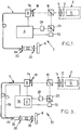
- the determination device 2 comprises a monochromatic light source 4 suitable for emitting an incident light beam, a waveguide 6 capable of being crossed by an incident beam and by a beam reflected by the target sample 8, and means of calculation 9 of the polarization information from the reflected beam recovered at the output of the waveguide 6.
- the light beam is called “incident beam” over the entire path from the source 4 to the target sample 8, and “reflected beam” over the entire path of the target sample 8. to computing means 9.
- upstream and downstream are defined as a function of the direction of the light beam.
- the light source 4 is able to emit an incident light beam polarized rectilinearly in a predefined direction x.
- This light source 4 is, for example, constituted by a laser diode 10, a polarizer 12 and a half-wave plate 14.
- the polarizer 12 and the half-wave plate 14 are arranged downstream of the laser diode, considering the direction of the wave. incident beam. They are suitable for being crossed by the beam emitted by the laser diode 10.
- the light source 4 can include a device intended to protect it from external reflections.
- the determination device 2 comprises between the light source 4 and the waveguide 6, a beam splitter cube 16 as well as a system 18 for focusing the beam incident in the waveguide 6.
- Cube 16 is polarization neutral. It only affects the intensity of the beam coming from the light source 4 and going towards the waveguide 6. It is able to modify the direction of the reflected beam to direct it towards the calculation means 9.
- the focusing system 18 is constituted, for example, by a microscope objective or a converging lens, the focal plane of which is located at the entrance of the waveguide 6.
- the waveguide 6 is suitable for guiding the incident beam on the target sample 8, in particular when the latter is positioned in a cavity or a recess, or even in the human body, so that it cannot be achieved by transmission of a light beam in direct sight. It comprises an end 6a called the proximal end, located near the light source 4 and the calculation means 9, and an end 6b called the distal end, intended to be placed near the target sample 8.
- the waveguide 6 is formed by a single-mode optical fiber at the wavelength of the beam emitted by the light source 4.
- Means 19 for varying the birefringence of waveguide 6 are mounted on waveguide 6. These means 19 have the effect of varying the polarization of the beam passing through the waveguide. These variation means 19 include, for example, means suitable for making the waveguide 6 vibrate, means suitable for generating a field electrical or means capable of varying the temperature or the pressure exerted on it, in order to temporally vary the polarization of the beam at the output of the waveguide 6.
- the variation means 19 are connected to the calculation means 9 and are controlled by the latter.
- Passing through waveguide 6 modifies the incident beam so that, at the output of waveguide 6, it has two orthogonal polarimetric components E ⁇ I and E ⁇ I.
- This modification is due both to the effect of the birefringence of the waveguide 6 and to the effect of the polarization variation means 19.
- the determination device 2 comprises, considering the direction of the incident beam, a first optical system 20 whose focal plane is located at the level of the opening of the distal end of the waveguide 6, polarization rotation means 22, and a second optical system 24 whose focal plane is located at the level of the target sample 8.
- the first optical system 20 is suitable for collimating the incident beam.
- the second optical system 24 is suitable for focusing the incident beam on the measuring point of the target sample.
- the reflected beam After reflection on the target sample 8, the reflected beam is collimated by the second optical system 24, it passes through the rotation means 22 and is focused by the first optical system 20 at the entrance of the distal part 6b of the guide d 'wave.
- the rotation means 22 comprise a Faraday rotator. For medical applications, this rotator is miniaturized.
- the Faraday rotator After reflection of the incident beam on the target sample 8, the Faraday rotator is suitable for rotating two orthogonal polarimetric components of the beam reflected referenced E ⁇ R and E ⁇ R at an angle of 45 degrees in the same direction of rotation to obtain two orthogonal polarimetric components referenced E ⁇ RR and E ⁇ RR .
- the polarimetric components E ⁇ IR and E ⁇ IR of the incident beam downstream from the rotation means 22 are different from the polarimetric components E ⁇ R and E ⁇ R of the reflected beam in upstream of the rotation means 24.
- the term downstream is defined by considering the direction of the incident beam.
- the term upstream is defined by considering the direction of the reflected beam.
- the waveguide 6 is suitable for guiding the reflected beam towards the focusing system 18.
- the polarimetric components E ⁇ RR and E ⁇ RR coming from the rotator 22 are again modified by the waveguide 6 and by the variation means 19 in an identical manner or by the less similar to changes made during the journey to the target sample 8.
- the determination device 2 further comprises a polarization splitter cube 26 and two photodetectors 28, 30 connected to the calculation means 9.
- the cube 26 is shaped to separate a polarimetric component E ⁇ F oriented in the predefined direction x, that is to say in the direction in which the light source 4 has polarized the incident beam, and a polarimetric component E ⁇ F orthogonal to this one.
- the parallel polarimetric component E ⁇ F and the orthogonal polarimetric component E ⁇ F of the reflected beam are directed respectively towards the photodetector 28, and towards the photodetector 30.
- the photodetectors 28, 30 each deliver a photocurrent, hereinafter called an electrical signal, to the means of calculation 9.
- the polarimetric components E ⁇ F and E ⁇ F vary over time due to the polarization variations generated by the variation means 19.
- An example of variation of the parallel polarimetric component E ⁇ F is represented on the figure 2 for a target sample having a phase shift of 90 degrees between its own axes.
- the calculation means 9 are suitable for selecting the maximum value of the electrical signal representative of the parallel polarimetric component E ⁇ F as well as the corresponding value of the electrical signal representative of the perpendicular polarimetric component E ⁇ F , that is to say the value measured at the same time or in other words the minimum value thereof.
- the calculation means 9 are also suitable for selecting the minimum value of the electrical signal representative of the parallel polarimetric component E ⁇ F as well as the corresponding value of the electrical signal representative of the perpendicular polarimetric component E ⁇ F , that is to say the value measured at the same time or in other words the maximum value thereof.
- the figure 3 represents a polarimetric imager 32 according to a first embodiment of the invention.
- the imager 32 is formed from a device 2 for determining polarization information, as described above, equipped with a unit 34 for constructing a polarimetric image and with a scanning system 36.
- the construction unit 34 is able to receive the values of the degree of polarization of the beam and the values of the phase shift originating from several measurement points of the target sample 8 and to construct two polarimetric images from them.
- Each grayscale or chroma of one pixel of the first frame represents the degree of polarization associated with a measurement point of the target sample.
- Each gray level or each chrominance of a pixel in the second image represents the phase shift at a measurement point of the target sample.
- the imaging unit 34 is synchronized with the scanning system 36.
- the scanning system 36 is able to direct the incident beam towards several measuring points of the target sample 8.
- It is arranged downstream of the waveguide 6, considering the direction of travel of the incident beam. In particular, it is arranged between the distal end 6b of the waveguide and the first optical system 20.
- It is for example formed by two oscillating mirrors, one along a vertical axis, and the other along a horizontal axis, at a frequency corresponding to the frequency of construction of an image by unit 34. It is connected to the building unit 34 by an electric wire 38.
- the figure 4 represents a polarimetric imager 32 according to a second embodiment of the invention. It is similar to the imager shown in the figure 3 .
- the waveguide 6 is replaced by several waveguides 40, or by a multicore optical fiber, and the scanning system 36 is disposed upstream of the waveguides considering the direction of the incident beam.
- the scanning system 36 is able to direct the incident beam in turn towards each waveguide so that the beam successively illuminates several measurement points of the target sample 8.
- the scanning system sequentially processes the signal. reflected beam.
- the construction unit 34 is synchronized with the scanning system 36 so as to be able to attribute to each polarization information calculated by the calculation unit 9 a corresponding position on the target sample 8.
- the figure 5 shows a polarimetric imager 32 not covered by the claims. It is similar to the imager shown in the figure 4 . However, the means 19 for varying the birefringence are replaced by means 42 for varying the polarization mounted between the cube 16 and the scanning system 36.
- the means 42 for varying the polarization consist, for example, of a polarization scrambler or an arrangement of phase plates controlled by the calculation unit 9.
- the means 42 for varying the polarization can also be used (instead of the means 19 for varying the birefringence) in the determination device illustrated in FIG. figure 1 , as well as in the imagers shown on the figures 2 to 4 .
- the figure 6 represents a polarimetric imager 32 according to a fourth embodiment of the invention. It is similar to the imager shown in the figure 5 . However, the monochromatic light source has been replaced by a polychromatic source 44 and the polarization variation means 42 have been eliminated.
- the polychromatic source is, for example, constituted by a superluminescent diode.
- the variation in polarization carried out previously by the variation means 19 or 42 is here induced by the passage through the waveguides d 'a broad spectrum beam.
- the calculation means 9 are suitable for selecting the maximum value and the minimum value of the electric signal representative of the parallel polarimetric component E ⁇ F from among the components of the electric field having different wavelengths.
- the value of the perpendicular polarimetric component E ⁇ F having the same wavelength is selected to calculate the degree of polarization and the phase shift.
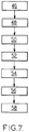
- the invention also relates to a method for determining polarization information illustrated on the figure 7 .
- the method begins with a step 46 of emitting a rectilinearly polarized incident light beam.
- the incident beam is guided towards the measuring point of the target sample using the waveguide 6.
- two orthogonal polarimetric components of the incident beam are rotated by an angle of 45 degrees by the Faraday rotator 22.
- the incident beam is retro-reflected on the measurement point of the target sample.
- a step 54 two orthogonal polarimetric components of the reflected beam are rotated by an angle of 45 degrees. Then, the reflected beam is injected into the waveguide 6 by the optical system 20.
- the reflected beam is guided towards the calculation unit 9 by the same waveguide 6.
- the polarization information of the measurement point of the target sample is calculated from the reflected beam recovered at the output of the waveguide 6.
- the phase shift provides, for example, information on the birefringence of the target sample while the degree of polarization provides information on its ability to depolarize light.
- the determination device 2 where the polarimetric imager 32 comprises a first rotator disposed only on the path of the incident beam between the distal part 6b and the target sample 8, and a second rotator disposed only on the path of the reflected beam between the distal part 6b and the target sample 8.
- the first rotator is suitable for rotating the polarimetric components of the beam by an angle ⁇ .
- the second rotator is suitable for rotating the polarimetric components by an angle 90- ⁇ degrees; ⁇ being between 0 and 90 degrees.
- the incident beam is not perpendicular to the surface of the target sample.
Landscapes
- Health & Medical Sciences (AREA)
- Life Sciences & Earth Sciences (AREA)
- Physics & Mathematics (AREA)
- General Health & Medical Sciences (AREA)
- Pathology (AREA)
- Biomedical Technology (AREA)
- Veterinary Medicine (AREA)
- Heart & Thoracic Surgery (AREA)
- Medical Informatics (AREA)
- Molecular Biology (AREA)
- Surgery (AREA)
- Animal Behavior & Ethology (AREA)
- Biophysics (AREA)
- Public Health (AREA)
- Engineering & Computer Science (AREA)
- General Physics & Mathematics (AREA)
- Spectroscopy & Molecular Physics (AREA)
- Chemical & Material Sciences (AREA)
- Analytical Chemistry (AREA)
- Biochemistry (AREA)
- Immunology (AREA)
- Nuclear Medicine, Radiotherapy & Molecular Imaging (AREA)
- Radiology & Medical Imaging (AREA)
- Investigating Or Analysing Materials By Optical Means (AREA)
Claims (11)
- Vorrichtung (2) zum Bestimmen mindestens einer Polarisationsinformation eines Messpunkts einer Zielprobe (8), wobei die Vorrichtung (2) Folgendes aufweist:- eine Lichtquelle (4; 44), welche in der Lage ist, einen polarisierten Lichtstrahl geradlinig in eine vorbestimmte Richtung auszusenden, wobei der Lichtstrahl dazu bestimmt ist, durch den Messpunkt der Zielprobe (8) reflektiert zu werden;- Mittel zum Erfassen (28, 30) und Berechnen (9) der Polarisationsinformation des Messpunkts anhand des durch die Zielprobe (8) reflektierten Strahls;- mindestens einen Hohlwellenleiter (6; 40), welcher in der Lage ist, den einfallenden Strahl in Richtung der Zielprobe (8), und den reflektierten Strahl in Richtung der Berechnungsmittel (9) zu führen; wobei der Hohlwellenleiter (6; 40) ein Monomode-Lichtwellenleiter bei der oder bei jeder Wellenlänge des durch die Lichtquelle (4; 44) ausgesendeten Strahls ist, dadurch gekennzeichnet, dass er ferner Folgendes umfasst:- Mittel (22) zur Drehung der Polarisation, umfassend einen Faraday-Rotator, welche in der Lage sind, zwei polarimetrische rechtwinklige Komponenten (EI ∥, EI ⊥) des einfallenden Strahls nach Passieren durch den Hohlwellenleiter (6; 40) und zwei polarimetrische rechtwinklige Komponenten (ER ∥, ER ⊥) des reflektierten Strahls vor Passieren durch den Hohlwellenleiter (6; 40) in einer Weise zu drehen, dass der Effekt der Doppeltbrechung des Hohlwellenleiters (6; 40) kompensiert wird; und- Mittel (19; 44) zur Variation der Polarisation des einfallenden Strahls und des reflektierten Strahls, welche entweder in Form von Mitteln (19) zur Variation der Doppeltbrechung des Hohlwellenleiters vorliegen, welche an dem Hohlwellenleiter montiert sind, für welche die Lichtquelle (4) monochromatisch ist und die geeignet sind, im Zeitverlauf und in identischer Weise die rechtwinkligen polarimetrischen Komponenten (EI ∥, EI ⊥) des einfallenden Strahls nach Passieren durch den Hohlwellenleiter und die rechtwinkligen Komponenten (EF ∥, EF ⊥) der Polarisation des reflektierten Strahls nach Passieren durch den Hohlwellenleiter zu modifizieren, oder welche durch die Lichtquelle in Form einer polychromatischen Lichtquelle (44) bereitgestellt werden, wobei die chromatische Abhängigkeit der Doppeltbrechung des Hohlwellenleiters so die Mittel zur Variation der Polarisation des einfallenden Strahls und des reflektierten Strahls bildet, wobei die Mittel (19; 44) zur Variation der Polarisation des einfallenden Strahls und des reflektierten Strahls so geartet sind, dass sie es ermöglichen, die Polarisationsinformation des Messpunkts anhand der Messungen für jede Polarisation des einfallenden Strahls zu berechnen.
- Vorrichtung (2) nach Anspruch 1, wobei die Drehmittel (22) in der Lage sind, die polarimetrischen Komponenten (EI ∥, EI ⊥) des einfallenden Strahls und die polarimetrischen Komponenten (ER ∥, ER ⊥) des reflektierten Strahls in eine gleiche Drehrichtung zu drehen.
- Vorrichtung (2) nach einem der Ansprüche 1 und 2, wobei die Drehmittel (22) einen einzigen Faraday-Rotator umfassen, welcher in der Lage ist, die polarimetrischen Komponenten (EI ∥, EI ⊥) des einfallenden Strahls und die polarimetrischen Komponenten (ER ∥, ER ⊥) des reflektierten Strahls um einen Winkel von 45 Grad zu drehen.
- Vorrichtung (2) nach einem der Ansprüche 1 und 2, wobei die Drehmittel (22) mindestens zwei Faraday-Rotaroren umfassen, welche in der Lage sind, die polarimetrischen Komponenten (EI ∥, EI ⊥) des einfallenden Strahls und die polarimetrischen Komponenten (ER ∥, ER ⊥) des reflektierten Strahls, eines um einen Winkel von α Grad und das andere um einen Winkel von 90- α Grad zu drehen; wobei α eine Zahl zwischen 0 und 90 Grad ist.
- Vorrichtung (2) nach einem der Ansprüche 1 bis 4, wobei der Hohlwellenleiter (6; 40) ein proximales Ende (6a; 40a) aufweist, welches dazu bestimmt ist, auf der Seite der Lichtquelle (4; 44) angeordnet zu sein, und ein distales Ende (6b; 40b), welches dazu bestimmt ist, auf der Seite der Zielprobe (8) angeordnet zu sein, wobei die Drehmittel (22) zwischen der Zielprobe (8) und dem distalen Ende (6b; 40b) des Hohlwellenleiters (6; 40) angeordnet sind.
- Vorrichtung (2) nach einem der Ansprüche 1 bis 5, Folgendes aufweist:- Mittel (26, 28, 30) zum Messen des reflektierten Strahls, welche in der Lage sind, ein elektrisches Signal abzugeben, welches die polarimetrische Komponente des reflektierten Strahls (E∥ RR) darstellt, welche entlang der vorbestimmten Richtung ausgerichtet ist, genannt paralleles Signal, und ein elektrisches Signal, welches die polarimetrische Komponente (E⊥ RR) darstellt, zu dieser rechtwinklig ist, genannt rechtwinkliges Signal; und wobei die Berechnungsmittel (9) Folgendes aufweisen:- Mittel zur Auswahl eines Wertes des parallelen Signals, wobei das parallele Signal im Zeitverlauf oder in Abhängigkeit von der Wellenlänge variiert; und- Mittel zur Messung der Polarisationsinformation des Messpunkts der Zielprobe (8) anhand des gewählten parallelen Signals und des zum gleichen Zeitpunkt gemessenen rechtwinkligen Signals, oder des rechtwinkligen Signals, welches dieselbe Wellenlänge aufweist.
- Vorrichtung (2) nach Anspruch 6, wobei der Wert des gewählten parallelen Signals der Mindestwert desselben, oder der maximale Wert desselben oder der Mittelwert desselben ist.
- Polarimetrische Bildgebungsvorrichtung (32), welche in der Lage ist, ein polarimetrisches Bild einer Zielprobe (8) zu erzeugen, wobei die Bildgebungsvorrichtung Folgendes umfasst:- eine Vorrichtung (2) zum Bestimmen einer Polarisationsinformation nach einem der Ansprüche 1 bis 7, wobei die Vorrichtung (2) geeignet ist, mehrere Polarisationsinformationen zu bestimmen;- eine Einheit (34) zur Konstruktion eines polarimetrischen Bildes, welches Polarisationsinformationen der Messpunkte der Zielprobe (8) darstellt, wobei jedes Merkmal eines Pixels des Bildes die Polarisationsinformation eines Messpunkts der Zielprobe (8) darstellt.
- Polarimetrische Bildgebungsvorrichtung (32) nach Anspruch 8, welche mehrere Hohlwellenleiter (40) und ein Abtastsystem (36) aufweisen, welches im vorgelagerten Bereich der Hohlwellenleiter (40) unter Betrachtung der Richtung des einfallenden Strahls angeordnet ist, wobei das Abtastsystem (36) geeignet ist, den einfallenden Strahl in Richtung mehrerer Messpunkte der Zielprobe (8) zu richten, wobei das Abtastsystem (36) durch die Bildkonstruktionseinheit (34) gesteuert wird und mit dieser synchronisiert ist.
- Polarimetrische Bildgebungsvorrichtung nach Anspruch 8, welche einen einzigen Hohlwellenleiter (6) und ein Abtastsystem (36) aufweist, welches im nachgelagerten Bereich des Hohlwellenleiters (6) unter Betrachtung der Richtung des einfallenden Strahls angeordnet ist, wobei das Abtastsystem (36) in der Lage ist, den einfallenden Strahl in Richtung mehrerer Messpunkte der Zielprobe (8) zu richten, wobei das Abtastsystem (36) durch die Bildkonstruktionseinheit (34) gesteuert wird und mit dieser synchronisiert ist.
- Verfahren zur Bestimmung mindestens einer Polarisationsinformation in einem Messpunkt einer Zielprobe (8), wobei das Verfahren folgende Schritte aufweist:- geradliniges Aussenden (46) eines einfallenden polarisierten Lichtstrahls in eine vorbestimmte Richtung;- Führen (48) des einfallenden Strahls in Richtung des Messpunkts der Zielprobe (8) mithilfe eines Hohlwellenleiters (6; 40), wobei der Leiter (6; 40) eine Monomode-Faser bei der oder bei jeder Wellenlänge des einfallenden Strahls ist,- Drehen (50) zweier rechtwinkliger polarimetrischer Komponenten des einfallenden Strahls nach Passieren durch den Hohlwellenleiter (6; 40) zum Kompensieren des Effekts der Doppeltbrechung des Hohlwellenleiters (6; 40) mit Mitteln (22) zum Drehen der Polarisation, welche einen Faraday-Rotator umfassen;- Reflektieren (52) des einfallenden Strahls auf den Messpunkt der Zielprobe (8);- Drehen (54) zweier rechtwinkliger polarimetrischer Komponenten des reflektierten Strahls vor Passieren durch den Hohlwellenleiter (6; 40) zum Kompensieren des Effekts der Doppeltbrechung des Hohlwellenleiters (6; 40) mit den Mitteln (22) zum Drehen der Polarisation;- Führen (56) des reflektierten Strahls in Richtung einer Berechnungseinheit (9) durch denselben Hohlwellenleiter (6; 40),- Variieren der Polarisation des einfallenden Strahls und des reflektierten Strahls mit Mitteln zum Variieren der Polarisation des einfallenden Strahls und des reflektierten Strahls, welche entweder in Form von Mitteln (19) zum Variieren der Doppeltbrechung des Hohlwellenleiters vorliegen, welche an dem Hohlwellenleiter montiert sind, für welche die Lichtquelle (4) monochromatisch ist und die geeignet sind, im Zeitverlauf und in identischer Weise die rechtwinkligen polarimetrischen Komponenten (EI ∥, EI ⊥) des einfallenden Strahls nach Passieren durch den Hohlwellenleiter und die rechtwinkligen Komponenten (EF ∥, EF ⊥) der Polarisation des reflektierten Strahls nach Passieren durch den Hohlwellenleiter zu modifizieren, oder welche durch die Lichtquelle in Form einer polychromatischen Lichtquelle (44) bereitgestellt werden, wobei die chromatische Abhängigkeit der Doppeltbrechung des Hohlwellenleiters so die Mittel zur Variation der Polarisation des einfallenden Strahls und des reflektierten Strahls bildet;- Detektieren des reflektierten Strahls für jede Polarisation des einfallenden Strahls und Berechnen (58) der Polarisationsinformation des Messpunktes der Zielprobe (8) anhand des reflektierten Strahls, welcher am Ausgang des Hohlwellenleiters (6; 40) abgefangen wird, anhand der durch jede Polarisation des einfallenden Strahls erzielten Messungen.
Applications Claiming Priority (3)
| Application Number | Priority Date | Filing Date | Title |
|---|---|---|---|
| FR0950236A FR2941047A1 (fr) | 2009-01-15 | 2009-01-15 | Dispositif et procede de determination d'une information de polarisation et imageur polarimetrique |
| FR0953402A FR2941045B1 (fr) | 2009-01-15 | 2009-05-20 | Dispositif et procede de determination d'une information de polarisation et imageur polarimetrique |
| PCT/FR2010/050063 WO2010081999A1 (fr) | 2009-01-15 | 2010-01-15 | Dispositif et procede de determination d'une information de polarisation et imageur polarimetrique. |
Publications (2)
| Publication Number | Publication Date |
|---|---|
| EP2376882A1 EP2376882A1 (de) | 2011-10-19 |
| EP2376882B1 true EP2376882B1 (de) | 2021-08-11 |
Family
ID=40855522
Family Applications (2)
| Application Number | Title | Priority Date | Filing Date |
|---|---|---|---|
| EP10706023A Withdrawn EP2376881A1 (de) | 2009-01-15 | 2010-01-15 | Vorrichtung und verfahren zur bestimmung von polarisationsinformationen und polarimetrische bildgebungsvorrichtung |
| EP10706703.5A Active EP2376882B1 (de) | 2009-01-15 | 2010-01-15 | Vorrichtung und verfahren zur bestimmung von polarisationsinformationen und polarimetrische bildgebungsvorrichtung |
Family Applications Before (1)
| Application Number | Title | Priority Date | Filing Date |
|---|---|---|---|
| EP10706023A Withdrawn EP2376881A1 (de) | 2009-01-15 | 2010-01-15 | Vorrichtung und verfahren zur bestimmung von polarisationsinformationen und polarimetrische bildgebungsvorrichtung |
Country Status (5)
| Country | Link |
|---|---|
| US (2) | US8896833B2 (de) |
| EP (2) | EP2376881A1 (de) |
| ES (1) | ES2896280T3 (de) |
| FR (3) | FR2941047A1 (de) |
| WO (2) | WO2010081999A1 (de) |
Families Citing this family (11)
| Publication number | Priority date | Publication date | Assignee | Title |
|---|---|---|---|---|
| US20120150710A1 (en) * | 2009-08-21 | 2012-06-14 | Hopac (Proprietary) Limited | method and system for facilitating access to financial information |
| CN105236390A (zh) | 2010-09-30 | 2016-01-13 | 株式会社Ihi | 石墨化炉及制造石墨的方法 |
| FR2977033B1 (fr) * | 2011-06-23 | 2013-07-05 | Univ Rennes | Systeme et procede d'analyse par determination d'un caractere depolarisant ou dichroique d'un objet |
| CN105814434A (zh) * | 2013-04-21 | 2016-07-27 | 莫拜尔欧西特有限公司 | 用于将来自样本表面的光和来自其更深漫射层的光分离的偏振光成像装置及其方法 |
| FR3018914B1 (fr) | 2014-03-18 | 2016-05-06 | Centre Nat Rech Scient | Dispositif et methode de caracterisation polarimetrique deportee |
| CN105606221B (zh) * | 2016-01-07 | 2018-02-23 | 湖南师范大学 | 一种波导型可调控检偏器 |
| EP4542167A1 (de) * | 2019-09-17 | 2025-04-23 | Carbon Autonomous Robotic Systems Inc. | Autonome laser-unkrautvernichtung |
| US12270903B2 (en) | 2021-03-17 | 2025-04-08 | Carbon Autonomous Robotic Systems Inc. | Systems and methods for point to point object matching and targeting |
| FR3123122B1 (fr) | 2021-05-20 | 2023-12-15 | KAMAX Innovative Systems | Dispositif de mesure d’informations polarimétriques et de fluorescence |
| EP4426108A1 (de) | 2021-11-02 | 2024-09-11 | Carbon Autonomous Robotic Systems Inc. | Beleuchtungssysteme mit hoher intensität und verfahren zur verwendung davon |
| IL312052A (en) | 2022-01-19 | 2024-06-01 | Carbon Autonomous Robotic Systems Inc | Systems and methods for object tracking and location prediction |
Citations (1)
| Publication number | Priority date | Publication date | Assignee | Title |
|---|---|---|---|---|
| EP0657974A2 (de) * | 1993-12-09 | 1995-06-14 | Hewlett-Packard Company | Polarisationsunabhängiger Picosekundenfaserlaser |
Family Cites Families (9)
| Publication number | Priority date | Publication date | Assignee | Title |
|---|---|---|---|---|
| US4626679A (en) * | 1982-09-22 | 1986-12-02 | Canon Kabushiki Kaisha | Optical head and method of detecting the focus thereof |
| US5206924A (en) * | 1992-01-31 | 1993-04-27 | The United States Of America As Represented By The Secretary Of The Navy | Fiber optic Michelson sensor and arrays with passive elimination of polarization fading and source feedback isolation |
| JPH063594A (ja) * | 1992-06-18 | 1994-01-14 | Nikon Corp | コンフォーカルレーザ走査微分干渉顕微鏡 |
| US5887009A (en) | 1997-05-22 | 1999-03-23 | Optical Biopsy Technologies, Inc. | Confocal optical scanning system employing a fiber laser |
| US6175669B1 (en) * | 1998-03-30 | 2001-01-16 | The Regents Of The Universtiy Of California | Optical coherence domain reflectometry guidewire |
| JP2000329690A (ja) * | 1999-05-20 | 2000-11-30 | Olympus Optical Co Ltd | 走査型共焦点光学装置 |
| US7126693B2 (en) * | 2004-03-29 | 2006-10-24 | Carl Zeiss Meditec, Inc. | Simple high efficiency optical coherence domain reflectometer design |
| US7289211B1 (en) | 2004-04-09 | 2007-10-30 | Walsh Jr Joseph T | System and method for imaging sub-surface polarization-sensitive material structures |
| EP1988373A1 (de) * | 2007-05-02 | 2008-11-05 | National University of Ireland Galway | Vektorielles Polarimetrieverfahren und Vorrichtung zum Analysieren des aus der Interaktion zwischen einem fokussierten Beleuchtungsfeld und einer zu beobachtenden Probe resultierenden dreidimensionalen elektromagnetischen Feldes |
-
2009
- 2009-01-15 FR FR0950236A patent/FR2941047A1/fr active Pending
- 2009-01-28 FR FR0950535A patent/FR2941048B1/fr not_active Expired - Fee Related
- 2009-05-20 FR FR0953402A patent/FR2941045B1/fr not_active Expired - Fee Related
-
2010
- 2010-01-15 ES ES10706703T patent/ES2896280T3/es active Active
- 2010-01-15 EP EP10706023A patent/EP2376881A1/de not_active Withdrawn
- 2010-01-15 WO PCT/FR2010/050063 patent/WO2010081999A1/fr not_active Ceased
- 2010-01-15 US US13/144,519 patent/US8896833B2/en active Active
- 2010-01-15 EP EP10706703.5A patent/EP2376882B1/de active Active
- 2010-01-15 US US13/144,311 patent/US8665436B2/en not_active Expired - Fee Related
- 2010-01-15 WO PCT/FR2010/050064 patent/WO2010082000A1/fr not_active Ceased
Patent Citations (1)
| Publication number | Priority date | Publication date | Assignee | Title |
|---|---|---|---|---|
| EP0657974A2 (de) * | 1993-12-09 | 1995-06-14 | Hewlett-Packard Company | Polarisationsunabhängiger Picosekundenfaserlaser |
Non-Patent Citations (1)
| Title |
|---|
| MARTINELLI ET AL: "A universal compensator for polarization changes induced by birefringence on a retracing beam", OPTICS COMMUNICATIONS, ELSEVIER, AMSTERDAM, NL, vol. 72, no. 6, 15 August 1989 (1989-08-15), pages 341 - 344, XP024466802, ISSN: 0030-4018, [retrieved on 19890815], DOI: 10.1016/0030-4018(89)90436-7 * |
Also Published As
| Publication number | Publication date |
|---|---|
| WO2010082000A1 (fr) | 2010-07-22 |
| US8665436B2 (en) | 2014-03-04 |
| US20110292389A1 (en) | 2011-12-01 |
| US20110273711A1 (en) | 2011-11-10 |
| ES2896280T3 (es) | 2022-02-24 |
| EP2376881A1 (de) | 2011-10-19 |
| FR2941048A1 (fr) | 2010-07-16 |
| EP2376882A1 (de) | 2011-10-19 |
| FR2941048B1 (fr) | 2016-08-05 |
| FR2941045A1 (fr) | 2010-07-16 |
| US8896833B2 (en) | 2014-11-25 |
| FR2941047A1 (fr) | 2010-07-16 |
| WO2010081999A1 (fr) | 2010-07-22 |
| FR2941045B1 (fr) | 2011-05-06 |
Similar Documents
| Publication | Publication Date | Title |
|---|---|---|
| EP2376882A1 (de) | Vorrichtung und verfahren zur bestimmung von polarisationsinformationen und polarimetrische bildgebungsvorrichtung | |
| US12369778B2 (en) | Method and apparatus for fiber optic photothermal imaging and spectroscopy | |
| EP0985902B1 (de) | Interferometrische Vorrichtung zum Sichtbarmachung von Optischen Reflexion- und/oder Transmissionscharakteristiken im inneren eines Objektes | |
| EP0581871B1 (de) | Vorrichtung für optische abbildung und messung | |
| EP3120134B1 (de) | Vorrichtung und verfahren zur polarimetrischen fernbestimmung | |
| TWI397715B (zh) | 使用頻率域干涉法用以執行光學成像之方法及設備 | |
| EP2852815B1 (de) | Chromatischer höhenmesswandler | |
| EP4185914A1 (de) | Systeme und verfahren zur durchführung einer mikroskopischen analyse einer probe | |
| EP1084379B1 (de) | Optoelektronische Formerfassung durch chromatische Kodierung mit Beleuchtungsebenen | |
| EP0840158B1 (de) | Vorrichtung zur Bestimmung von Phasenfehlern elektromagnetischer Wellen | |
| EP0645645B1 (de) | Lasersonde für Geschwindigkeits- und Neigungsmessung | |
| US20180238676A1 (en) | Method and apparatus for deriving a topography of an object surface | |
| EP4078217B1 (de) | Lidar-system mit zwei diffraktiven komponenten | |
| FR3123122A1 (fr) | Dispositif de mesure d’informations polarimétriques et de fluorescence | |
| WO2025099033A1 (fr) | Appareil et procédé de micro-spectrométrie raman confocal avec système de mise au point | |
| EP3367881B1 (de) | Vorrichtung zur messung der geschwindigkeit von blut in einem blutgefäss des auges | |
| FR3164017A1 (fr) | Dispositif de mesure polarimétrique par interférométrie spectrale de grandeurs anisotropiques d’un milieu, et procédé de mesure correspondant | |
| FR3054320A1 (fr) | Dispositif et procede pour la caracterisation d'echantillons par imagerie de spectroscopie pwr | |
| WO2010066969A1 (fr) | Dispositif et procede d'imagerie par detection non-lineaire | |
| FR2928729A1 (fr) | Dispositif de detection ou de reception d'un rayonnement laser |
Legal Events
| Date | Code | Title | Description |
|---|---|---|---|
| PUAI | Public reference made under article 153(3) epc to a published international application that has entered the european phase |
Free format text: ORIGINAL CODE: 0009012 |
|
| 17P | Request for examination filed |
Effective date: 20110711 |
|
| AK | Designated contracting states |
Kind code of ref document: A1 Designated state(s): AT BE BG CH CY CZ DE DK EE ES FI FR GB GR HR HU IE IS IT LI LT LU LV MC MK MT NL NO PL PT RO SE SI SK SM TR |
|
| DAX | Request for extension of the european patent (deleted) | ||
| STAA | Information on the status of an ep patent application or granted ep patent |
Free format text: STATUS: EXAMINATION IS IN PROGRESS |
|
| 17Q | First examination report despatched |
Effective date: 20190607 |
|
| GRAP | Despatch of communication of intention to grant a patent |
Free format text: ORIGINAL CODE: EPIDOSNIGR1 |
|
| STAA | Information on the status of an ep patent application or granted ep patent |
Free format text: STATUS: GRANT OF PATENT IS INTENDED |
|
| INTG | Intention to grant announced |
Effective date: 20210311 |
|
| GRAS | Grant fee paid |
Free format text: ORIGINAL CODE: EPIDOSNIGR3 |
|
| GRAA | (expected) grant |
Free format text: ORIGINAL CODE: 0009210 |
|
| STAA | Information on the status of an ep patent application or granted ep patent |
Free format text: STATUS: THE PATENT HAS BEEN GRANTED |
|
| AK | Designated contracting states |
Kind code of ref document: B1 Designated state(s): AT BE BG CH CY CZ DE DK EE ES FI FR GB GR HR HU IE IS IT LI LT LU LV MC MK MT NL NO PL PT RO SE SI SK SM TR |
|
| REG | Reference to a national code |
Ref country code: GB Ref legal event code: FG4D Free format text: NOT ENGLISH |
|
| REG | Reference to a national code |
Ref country code: CH Ref legal event code: EP |
|
| REG | Reference to a national code |
Ref country code: DE Ref legal event code: R096 Ref document number: 602010067401 Country of ref document: DE |
|
| REG | Reference to a national code |
Ref country code: IE Ref legal event code: FG4D Free format text: LANGUAGE OF EP DOCUMENT: FRENCH Ref country code: AT Ref legal event code: REF Ref document number: 1419848 Country of ref document: AT Kind code of ref document: T Effective date: 20210915 |
|
| REG | Reference to a national code |
Ref country code: LT Ref legal event code: MG9D |
|
| REG | Reference to a national code |
Ref country code: NL Ref legal event code: MP Effective date: 20210811 |
|
| REG | Reference to a national code |
Ref country code: AT Ref legal event code: MK05 Ref document number: 1419848 Country of ref document: AT Kind code of ref document: T Effective date: 20210811 |
|
| PG25 | Lapsed in a contracting state [announced via postgrant information from national office to epo] |
Ref country code: HR Free format text: LAPSE BECAUSE OF FAILURE TO SUBMIT A TRANSLATION OF THE DESCRIPTION OR TO PAY THE FEE WITHIN THE PRESCRIBED TIME-LIMIT Effective date: 20210811 Ref country code: SE Free format text: LAPSE BECAUSE OF FAILURE TO SUBMIT A TRANSLATION OF THE DESCRIPTION OR TO PAY THE FEE WITHIN THE PRESCRIBED TIME-LIMIT Effective date: 20210811 Ref country code: AT Free format text: LAPSE BECAUSE OF FAILURE TO SUBMIT A TRANSLATION OF THE DESCRIPTION OR TO PAY THE FEE WITHIN THE PRESCRIBED TIME-LIMIT Effective date: 20210811 Ref country code: BG Free format text: LAPSE BECAUSE OF FAILURE TO SUBMIT A TRANSLATION OF THE DESCRIPTION OR TO PAY THE FEE WITHIN THE PRESCRIBED TIME-LIMIT Effective date: 20211111 Ref country code: LT Free format text: LAPSE BECAUSE OF FAILURE TO SUBMIT A TRANSLATION OF THE DESCRIPTION OR TO PAY THE FEE WITHIN THE PRESCRIBED TIME-LIMIT Effective date: 20210811 Ref country code: NO Free format text: LAPSE BECAUSE OF FAILURE TO SUBMIT A TRANSLATION OF THE DESCRIPTION OR TO PAY THE FEE WITHIN THE PRESCRIBED TIME-LIMIT Effective date: 20211111 Ref country code: PT Free format text: LAPSE BECAUSE OF FAILURE TO SUBMIT A TRANSLATION OF THE DESCRIPTION OR TO PAY THE FEE WITHIN THE PRESCRIBED TIME-LIMIT Effective date: 20211213 Ref country code: FI Free format text: LAPSE BECAUSE OF FAILURE TO SUBMIT A TRANSLATION OF THE DESCRIPTION OR TO PAY THE FEE WITHIN THE PRESCRIBED TIME-LIMIT Effective date: 20210811 |
|
| REG | Reference to a national code |
Ref country code: ES Ref legal event code: FG2A Ref document number: 2896280 Country of ref document: ES Kind code of ref document: T3 Effective date: 20220224 |
|
| PG25 | Lapsed in a contracting state [announced via postgrant information from national office to epo] |
Ref country code: PL Free format text: LAPSE BECAUSE OF FAILURE TO SUBMIT A TRANSLATION OF THE DESCRIPTION OR TO PAY THE FEE WITHIN THE PRESCRIBED TIME-LIMIT Effective date: 20210811 Ref country code: LV Free format text: LAPSE BECAUSE OF FAILURE TO SUBMIT A TRANSLATION OF THE DESCRIPTION OR TO PAY THE FEE WITHIN THE PRESCRIBED TIME-LIMIT Effective date: 20210811 Ref country code: GR Free format text: LAPSE BECAUSE OF FAILURE TO SUBMIT A TRANSLATION OF THE DESCRIPTION OR TO PAY THE FEE WITHIN THE PRESCRIBED TIME-LIMIT Effective date: 20211112 |
|
| PG25 | Lapsed in a contracting state [announced via postgrant information from national office to epo] |
Ref country code: NL Free format text: LAPSE BECAUSE OF FAILURE TO SUBMIT A TRANSLATION OF THE DESCRIPTION OR TO PAY THE FEE WITHIN THE PRESCRIBED TIME-LIMIT Effective date: 20210811 |
|
| PG25 | Lapsed in a contracting state [announced via postgrant information from national office to epo] |
Ref country code: DK Free format text: LAPSE BECAUSE OF FAILURE TO SUBMIT A TRANSLATION OF THE DESCRIPTION OR TO PAY THE FEE WITHIN THE PRESCRIBED TIME-LIMIT Effective date: 20210811 |
|
| REG | Reference to a national code |
Ref country code: DE Ref legal event code: R097 Ref document number: 602010067401 Country of ref document: DE |
|
| PG25 | Lapsed in a contracting state [announced via postgrant information from national office to epo] |
Ref country code: SM Free format text: LAPSE BECAUSE OF FAILURE TO SUBMIT A TRANSLATION OF THE DESCRIPTION OR TO PAY THE FEE WITHIN THE PRESCRIBED TIME-LIMIT Effective date: 20210811 Ref country code: SK Free format text: LAPSE BECAUSE OF FAILURE TO SUBMIT A TRANSLATION OF THE DESCRIPTION OR TO PAY THE FEE WITHIN THE PRESCRIBED TIME-LIMIT Effective date: 20210811 Ref country code: RO Free format text: LAPSE BECAUSE OF FAILURE TO SUBMIT A TRANSLATION OF THE DESCRIPTION OR TO PAY THE FEE WITHIN THE PRESCRIBED TIME-LIMIT Effective date: 20210811 Ref country code: EE Free format text: LAPSE BECAUSE OF FAILURE TO SUBMIT A TRANSLATION OF THE DESCRIPTION OR TO PAY THE FEE WITHIN THE PRESCRIBED TIME-LIMIT Effective date: 20210811 Ref country code: CZ Free format text: LAPSE BECAUSE OF FAILURE TO SUBMIT A TRANSLATION OF THE DESCRIPTION OR TO PAY THE FEE WITHIN THE PRESCRIBED TIME-LIMIT Effective date: 20210811 |
|
| PLBE | No opposition filed within time limit |
Free format text: ORIGINAL CODE: 0009261 |
|
| STAA | Information on the status of an ep patent application or granted ep patent |
Free format text: STATUS: NO OPPOSITION FILED WITHIN TIME LIMIT |
|
| 26N | No opposition filed |
Effective date: 20220512 |
|
| PG25 | Lapsed in a contracting state [announced via postgrant information from national office to epo] |
Ref country code: IT Free format text: LAPSE BECAUSE OF FAILURE TO SUBMIT A TRANSLATION OF THE DESCRIPTION OR TO PAY THE FEE WITHIN THE PRESCRIBED TIME-LIMIT Effective date: 20210811 |
|
| PG25 | Lapsed in a contracting state [announced via postgrant information from national office to epo] |
Ref country code: SI Free format text: LAPSE BECAUSE OF FAILURE TO SUBMIT A TRANSLATION OF THE DESCRIPTION OR TO PAY THE FEE WITHIN THE PRESCRIBED TIME-LIMIT Effective date: 20210811 Ref country code: MC Free format text: LAPSE BECAUSE OF FAILURE TO SUBMIT A TRANSLATION OF THE DESCRIPTION OR TO PAY THE FEE WITHIN THE PRESCRIBED TIME-LIMIT Effective date: 20210811 |
|
| REG | Reference to a national code |
Ref country code: BE Ref legal event code: MM Effective date: 20220131 |
|
| PG25 | Lapsed in a contracting state [announced via postgrant information from national office to epo] |
Ref country code: LU Free format text: LAPSE BECAUSE OF NON-PAYMENT OF DUE FEES Effective date: 20220115 |
|
| PG25 | Lapsed in a contracting state [announced via postgrant information from national office to epo] |
Ref country code: BE Free format text: LAPSE BECAUSE OF NON-PAYMENT OF DUE FEES Effective date: 20220131 |
|
| PG25 | Lapsed in a contracting state [announced via postgrant information from national office to epo] |
Ref country code: IE Free format text: LAPSE BECAUSE OF NON-PAYMENT OF DUE FEES Effective date: 20220115 |
|
| PGFP | Annual fee paid to national office [announced via postgrant information from national office to epo] |
Ref country code: FR Payment date: 20230331 Year of fee payment: 15 |
|
| PG25 | Lapsed in a contracting state [announced via postgrant information from national office to epo] |
Ref country code: HU Free format text: LAPSE BECAUSE OF FAILURE TO SUBMIT A TRANSLATION OF THE DESCRIPTION OR TO PAY THE FEE WITHIN THE PRESCRIBED TIME-LIMIT; INVALID AB INITIO Effective date: 20100115 |
|
| PG25 | Lapsed in a contracting state [announced via postgrant information from national office to epo] |
Ref country code: MK Free format text: LAPSE BECAUSE OF FAILURE TO SUBMIT A TRANSLATION OF THE DESCRIPTION OR TO PAY THE FEE WITHIN THE PRESCRIBED TIME-LIMIT Effective date: 20210811 Ref country code: CY Free format text: LAPSE BECAUSE OF FAILURE TO SUBMIT A TRANSLATION OF THE DESCRIPTION OR TO PAY THE FEE WITHIN THE PRESCRIBED TIME-LIMIT Effective date: 20210811 |
|
| PGFP | Annual fee paid to national office [announced via postgrant information from national office to epo] |
Ref country code: DE Payment date: 20240228 Year of fee payment: 15 Ref country code: GB Payment date: 20240131 Year of fee payment: 15 Ref country code: CH Payment date: 20240202 Year of fee payment: 15 |
|
| PG25 | Lapsed in a contracting state [announced via postgrant information from national office to epo] |
Ref country code: TR Free format text: LAPSE BECAUSE OF FAILURE TO SUBMIT A TRANSLATION OF THE DESCRIPTION OR TO PAY THE FEE WITHIN THE PRESCRIBED TIME-LIMIT Effective date: 20210811 |
|
| PGFP | Annual fee paid to national office [announced via postgrant information from national office to epo] |
Ref country code: ES Payment date: 20240328 Year of fee payment: 15 |
|
| PG25 | Lapsed in a contracting state [announced via postgrant information from national office to epo] |
Ref country code: MT Free format text: LAPSE BECAUSE OF FAILURE TO SUBMIT A TRANSLATION OF THE DESCRIPTION OR TO PAY THE FEE WITHIN THE PRESCRIBED TIME-LIMIT Effective date: 20210811 |
|
| REG | Reference to a national code |
Ref country code: DE Ref legal event code: R119 Ref document number: 602010067401 Country of ref document: DE |
|
| REG | Reference to a national code |
Ref country code: CH Ref legal event code: PL |
|
| GBPC | Gb: european patent ceased through non-payment of renewal fee |
Effective date: 20250115 |
|
| PG25 | Lapsed in a contracting state [announced via postgrant information from national office to epo] |
Ref country code: DE Free format text: LAPSE BECAUSE OF NON-PAYMENT OF DUE FEES Effective date: 20250801 |
|
| PG25 | Lapsed in a contracting state [announced via postgrant information from national office to epo] |
Ref country code: GB Free format text: LAPSE BECAUSE OF NON-PAYMENT OF DUE FEES Effective date: 20250115 |
|
| PG25 | Lapsed in a contracting state [announced via postgrant information from national office to epo] |
Ref country code: FR Free format text: LAPSE BECAUSE OF NON-PAYMENT OF DUE FEES Effective date: 20250131 |
|
| PG25 | Lapsed in a contracting state [announced via postgrant information from national office to epo] |
Ref country code: CH Free format text: LAPSE BECAUSE OF NON-PAYMENT OF DUE FEES Effective date: 20250131 |
|
| REG | Reference to a national code |
Ref country code: ES Ref legal event code: FD2A Effective date: 20260227 |
|
| PG25 | Lapsed in a contracting state [announced via postgrant information from national office to epo] |
Ref country code: ES Free format text: LAPSE BECAUSE OF NON-PAYMENT OF DUE FEES Effective date: 20250116 |