EP2377667A2 - Dispositif et procédé destinés à la manipulation d'un produit dans un récipient - Google Patents
Dispositif et procédé destinés à la manipulation d'un produit dans un récipient Download PDFInfo
- Publication number
- EP2377667A2 EP2377667A2 EP20110156018 EP11156018A EP2377667A2 EP 2377667 A2 EP2377667 A2 EP 2377667A2 EP 20110156018 EP20110156018 EP 20110156018 EP 11156018 A EP11156018 A EP 11156018A EP 2377667 A2 EP2377667 A2 EP 2377667A2
- Authority
- EP
- European Patent Office
- Prior art keywords
- holder
- product
- preform
- alignment
- container
- Prior art date
- Legal status (The legal status is an assumption and is not a legal conclusion. Google has not performed a legal analysis and makes no representation as to the accuracy of the status listed.)
- Withdrawn
Links
- 238000000034 method Methods 0.000 title claims abstract description 10
- 238000012546 transfer Methods 0.000 claims abstract description 20
- 238000000071 blow moulding Methods 0.000 claims description 8
- 238000004519 manufacturing process Methods 0.000 abstract description 2
- 238000010438 heat treatment Methods 0.000 description 5
- 230000005540 biological transmission Effects 0.000 description 3
- 238000010276 construction Methods 0.000 description 3
- 238000012937 correction Methods 0.000 description 3
- 230000035484 reaction time Effects 0.000 description 3
- 238000001746 injection moulding Methods 0.000 description 2
- 238000003780 insertion Methods 0.000 description 2
- 230000037431 insertion Effects 0.000 description 2
- 230000005855 radiation Effects 0.000 description 2
- 238000010521 absorption reaction Methods 0.000 description 1
- 238000013459 approach Methods 0.000 description 1
- 238000007664 blowing Methods 0.000 description 1
- 230000001419 dependent effect Effects 0.000 description 1
- 238000009795 derivation Methods 0.000 description 1
- 238000013461 design Methods 0.000 description 1
- 238000011161 development Methods 0.000 description 1
- 230000018109 developmental process Effects 0.000 description 1
- 230000005670 electromagnetic radiation Effects 0.000 description 1
- 239000000463 material Substances 0.000 description 1
- 238000012986 modification Methods 0.000 description 1
- 230000004048 modification Effects 0.000 description 1
- 238000012544 monitoring process Methods 0.000 description 1
- 230000003287 optical effect Effects 0.000 description 1
- 230000002093 peripheral effect Effects 0.000 description 1
- 239000007921 spray Substances 0.000 description 1
Images




Classifications
-
- B—PERFORMING OPERATIONS; TRANSPORTING
- B29—WORKING OF PLASTICS; WORKING OF SUBSTANCES IN A PLASTIC STATE IN GENERAL
- B29C—SHAPING OR JOINING OF PLASTICS; SHAPING OF MATERIAL IN A PLASTIC STATE, NOT OTHERWISE PROVIDED FOR; AFTER-TREATMENT OF THE SHAPED PRODUCTS, e.g. REPAIRING
- B29C49/00—Blow-moulding, i.e. blowing a preform or parison to a desired shape within a mould; Apparatus therefor
- B29C49/42—Component parts, details or accessories; Auxiliary operations
- B29C49/4205—Handling means, e.g. transfer, loading or discharging means
-
- B—PERFORMING OPERATIONS; TRANSPORTING
- B29—WORKING OF PLASTICS; WORKING OF SUBSTANCES IN A PLASTIC STATE IN GENERAL
- B29C—SHAPING OR JOINING OF PLASTICS; SHAPING OF MATERIAL IN A PLASTIC STATE, NOT OTHERWISE PROVIDED FOR; AFTER-TREATMENT OF THE SHAPED PRODUCTS, e.g. REPAIRING
- B29C2949/00—Indexing scheme relating to blow-moulding
- B29C2949/07—Preforms or parisons characterised by their configuration
- B29C2949/0715—Preforms or parisons characterised by their configuration the preform having one end closed
-
- B—PERFORMING OPERATIONS; TRANSPORTING
- B29—WORKING OF PLASTICS; WORKING OF SUBSTANCES IN A PLASTIC STATE IN GENERAL
- B29C—SHAPING OR JOINING OF PLASTICS; SHAPING OF MATERIAL IN A PLASTIC STATE, NOT OTHERWISE PROVIDED FOR; AFTER-TREATMENT OF THE SHAPED PRODUCTS, e.g. REPAIRING
- B29C49/00—Blow-moulding, i.e. blowing a preform or parison to a desired shape within a mould; Apparatus therefor
- B29C49/02—Combined blow-moulding and manufacture of the preform or the parison
- B29C49/06—Injection blow-moulding
-
- B—PERFORMING OPERATIONS; TRANSPORTING
- B29—WORKING OF PLASTICS; WORKING OF SUBSTANCES IN A PLASTIC STATE IN GENERAL
- B29C—SHAPING OR JOINING OF PLASTICS; SHAPING OF MATERIAL IN A PLASTIC STATE, NOT OTHERWISE PROVIDED FOR; AFTER-TREATMENT OF THE SHAPED PRODUCTS, e.g. REPAIRING
- B29C49/00—Blow-moulding, i.e. blowing a preform or parison to a desired shape within a mould; Apparatus therefor
- B29C49/42—Component parts, details or accessories; Auxiliary operations
- B29C49/4205—Handling means, e.g. transfer, loading or discharging means
- B29C49/42051—Means for stripping, aligning or de-stacking
- B29C49/42057—Aligning disorderly arranged preforms, e.g. delivered disorderly
-
- B—PERFORMING OPERATIONS; TRANSPORTING
- B29—WORKING OF PLASTICS; WORKING OF SUBSTANCES IN A PLASTIC STATE IN GENERAL
- B29C—SHAPING OR JOINING OF PLASTICS; SHAPING OF MATERIAL IN A PLASTIC STATE, NOT OTHERWISE PROVIDED FOR; AFTER-TREATMENT OF THE SHAPED PRODUCTS, e.g. REPAIRING
- B29C49/00—Blow-moulding, i.e. blowing a preform or parison to a desired shape within a mould; Apparatus therefor
- B29C49/42—Component parts, details or accessories; Auxiliary operations
- B29C49/4205—Handling means, e.g. transfer, loading or discharging means
- B29C49/42093—Transporting apparatus, e.g. slides, wheels or conveyors
- B29C49/42095—Rotating wheels or stars
-
- B—PERFORMING OPERATIONS; TRANSPORTING
- B29—WORKING OF PLASTICS; WORKING OF SUBSTANCES IN A PLASTIC STATE IN GENERAL
- B29C—SHAPING OR JOINING OF PLASTICS; SHAPING OF MATERIAL IN A PLASTIC STATE, NOT OTHERWISE PROVIDED FOR; AFTER-TREATMENT OF THE SHAPED PRODUCTS, e.g. REPAIRING
- B29C49/00—Blow-moulding, i.e. blowing a preform or parison to a desired shape within a mould; Apparatus therefor
- B29C49/42—Component parts, details or accessories; Auxiliary operations
- B29C49/4205—Handling means, e.g. transfer, loading or discharging means
- B29C49/42113—Means for manipulating the objects' position or orientation
- B29C49/42119—Rotation, e.g. rotating a predetermined angle for asymmetric preform or with asymmetric heat profile
-
- B—PERFORMING OPERATIONS; TRANSPORTING
- B29—WORKING OF PLASTICS; WORKING OF SUBSTANCES IN A PLASTIC STATE IN GENERAL
- B29C—SHAPING OR JOINING OF PLASTICS; SHAPING OF MATERIAL IN A PLASTIC STATE, NOT OTHERWISE PROVIDED FOR; AFTER-TREATMENT OF THE SHAPED PRODUCTS, e.g. REPAIRING
- B29C49/00—Blow-moulding, i.e. blowing a preform or parison to a desired shape within a mould; Apparatus therefor
- B29C49/42—Component parts, details or accessories; Auxiliary operations
- B29C49/42412—Marking or printing
- B29C49/42413—Marking or printing with a pattern for analysing deformation
Definitions
- the invention relates to a device for handling a container product according to the preamble of claim 1 and a method therefor according to the preamble of claim 13.
- a preform is usually first prepared, which contains the required amount of material for the finished container and preferably also the finished neck with thread and possibly a collar located under the thread or a collar, but in the remaining area smaller and thick-walled than the finished container is.
- This preform is preferably produced by injection molding.
- the preform is then inserted into a blow mold and deformed by compressed gas and optionally mechanical stretching to the finished container. Between the injection molding of the preform and the blow molding, the preform is preferably heated again. It may be advantageous or necessary for a variety of reasons to use the preform with a certain orientation in the blow mold.
- the position regulator includes a sensor that detects an alignment mark on the preform and determines if it is in the predetermined rotational angular position. If this is not the case, then the holder of the preform, which here consists of a mandrel on which the preform is plugged with the opening facing down, driven by a motor via a rack / sprocket transmission.
- This type of alignment correction is relatively complex and requires electronic control.
- the blow mold contains a gripping member which is inserted within the blow mold and before the blowing process in the neck region of the preform.
- a sensor device for example an optical device, detects an alignment mark on the preform and determines its position. If the position does not match the predetermined rotational angular position of the preform, the gripping member is rotated by a motor and a pinion / gear transmission. Again, the effort is relatively high.
- the rotation angle alignment takes place before the heating of the preform and by rotation of a holder, on which the preform is pushed upside down.
- the neck portion of the container is provided with two diametrically opposed projections which form a stop for two parallel and counter-rotating alignment fingers.
- the alignment fingers move on both sides over the neck area so that their faces are diametrically opposed.
- the carrier is rotated via a rack / sprocket transmission until the closest stop abuts the end face of the alignment finger. Again, this is relatively complex and at best suitable for a coarse alignment.
- the invention has for its object to provide an apparatus and a method for handling a container product, with a structurally simple and secure alignment of the angular position of the product is possible.
- the object is achieved by the device according to claim 1 and the method according to claim 13.
- the alignment device is preferably associated with the second transport device, since no error source for a renewed misalignment is opened when transferring to the second transport device.
- the positioning element of the alignment device which can be brought into a locking position, subsequently serves to maintain the correct rotational angle alignment which has already been achieved, without the need for additional precautions.
- the positioning element is preferably spring-loaded for this purpose.
- the positioning element also has a standby position apart from its locking position, the reaction time is reduced.
- the positioning element is preferably designed as a spring-loaded rocker arm, since this has a particularly short reaction time.
- reaction time is further reduced when the positioning element has an engagement projection and the alignment mark has an engagement recess, as this allows the projection to engage the recess immediately, while in a reverse arrangement the positioning element would first have to be lifted.
- the relative movement between the holders of the two transport devices, which can be exploited for rotating the product, is particularly easy to implement if at least one of the transport devices, but preferably both, has an at least approximately circular conveyor track.
- the derivation of the rotary drive for the product from the relative movement of the brackets is further facilitated if the conveyor tracks of the first and second transport means overlap in the transfer area, so that a direct tap of the relative movement is possible. It is particularly useful that overlap not only the conveyor paths but also the brackets of the first and second transport device in the transfer area, so that the product is still held by the first holder, while it is already in the access area of the second holder and the second Holder associated with alignment, and can rotate in the first holder about its longitudinal axis until it has reached its predetermined alignment position with respect to the second holder.
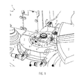
- Fig. 1 shows a transfer area Ü in a device 1 for handling a container product, in particular a container or a preform. Shown is a device for producing a container from a preform 2.
- the device 1 includes a first transport device 3 and a second transport device 4.
- a "transport device” is to be understood any device that is capable of a preform 2 or a to move the preform stretch blown container over a path.
- the first transport device 3 is a transfer star which takes over preforms from a pretreatment, for example directly from the spray device or from a heat treatment device, and transfers them to the second transport device 4, which is designed as a blow molding machine in the illustrated embodiment.
- the heating can be done with infrared radiation, but also by means of electromagnetic radiation such as microwave radiation.
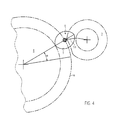
- Both transport devices 3, 4 have, as the Fig. 2 to 4 can be seen, an at least approximately circular circulating conveyor path about a corresponding axis 3 'and 4', wherein the axis is perpendicular.
- the first transport device 3 has at its periphery a plurality of holders 5, which in the illustrated embodiment each include a gripping tongs 5 a, which is able to engage under a collar 2 a disposed on the preform 2 and the preform 2 by perpendicularly extending central axis. 2 'and hold upward opening.
- the gripping tongs 5 a is arranged on a pivoting arm 5 b, which rotates about the axis 3 'of the first transporting device 3 and (compensated) can carry out compensating movements in a controlled manner.
- the swing arm is part of a pitch delay star. Its movement is controlled by two curves to bring the preforms that come out of the oven to the pitch of the blow mold. For this purpose, the preforms must be specifically accelerated, which is why a special curved path is necessary.
- the swing arm is mostly deflected from the Radial, at the closest approach of the two transport devices, however, he is exactly in the radial.
- Fig. 2 to 4 is only one of the curves, and of which a Kurben Siemens 30 is shown, which ensures that the brackets 5, 6 with the preforms 2 in the transfer area Ü parallel to each other.
- a further curve, not shown, is provided, which ensures that the pivot arm 5b is deflected in a suitable manner from the radial alignment to the axis 3 'to the peripheral speed of both transport devices 3, 4 and a possible pitch offset between the brackets 5 and the brackets 6 balance.
- the holder 5 of the first transport device 3 is able to slightly deflect when exposed to corresponding forces, for example in the radial direction or in the circumferential direction with respect to the axis of rotation 3 'to avoid damage to the preform.
- the second transport device 4 has a holder 6 for the preform 2, wherein the holder 6 is formed here by a mouth region of a blow mold 7.
- the blow mold 7 is, in Fig. 1 not visible, divisible in the usual way, so that the preform 2 can be used and the finished container can be removed. In the region of the holder 6, the blow mold 7 engages closely to the preform, so that the position of the preform 2 is fixed in the holder 6.
- Fig. 1 shows overlap in the transfer area Ü the transport paths of the holders 5 and 6, so that the preform can be used in a conventional manner in the blow mold. However, the insertion takes place in such a way that the preform can still be held by the first holder 5 while it is already in the second holder 6.
- the two holders 5, 6 over a relatively large angular range ⁇ accompanying move for example, is about 25 ° to 40 ° or 15 cm to 45 cm.
- ⁇ angular range
- the alignment device 8 includes a positioning element 9, which is formed in the illustrated embodiment as a rocker arm or pawl.
- the positioning member 9 includes a first arm 9a and an angle thereto extending second arm 9b.
- the positioning element 9 is pivotable about a pivot axis 10.
- the pivot axis 10 is disposed between the two arms 9a, 9b.
- the pivot axis 10 extends substantially parallel to the longitudinal center line 2 'of the preform 2.
- the positioning element 9 is attached via the pivot axis 10 to a support 11 which is arranged on the upper side of the blow mold 7.
- a spring 12 is arranged, which acts on one of the arms 9b of the positioning element 9.
- the other arm 9a of the positioning element 9 contains in the in the Fig. 7 and 8th illustrated embodiment, an engagement projection 13 which is dimensioned and configured so that it is formed in at least one recess formed as an alignment mark 14 on the preform 2 (see also Fig. 5 ) can engage such that the positioning element 9 holds the preform 2 and can rotate against the holding force in the first holder 5.
- the projection 13 is further dimensioned and shaped so that it prevents any further rotation of the preform relative to the second holder 6 and in both directions about the longitudinal center line 2 'when engaging in the alignment recess 14, the preform 2 thus in a predetermined position to the tuyere 7th locked.
- This locking position is in Fig. 8 shown.
- the recess 14 is how Fig. 5 shows, provided in a radially outwardly projecting collar 15 of the preform 2, which is arranged at a distance below the neck collar 2a and on which a cylindrical running surface 15a is provided.
- a running surface 15 a of the projection 13 of the positioning element 9 abuts when the projection 13 is not in the recess 14.
- the spring 12 is compressed, so that the positioning element 9 is pressed with a bias against the orbit 15a.
- This is a standby position ( Fig. 7 ) of the positioning element 9, from which the positioning element under load by the spring 12 immediately and without delay in the locking position ( Fig. 8 ) can move as soon as the brackets have moved 5 and 6 relative to each other in a position in which this is possible.
- the preform 2 is locked against any further rotation relative to the second holder 6 and thus to the blow mold 7.
- the grip of the first holder 5 on the preform 2 is not so strong that the preform 2 is damaged if it still sits in the first holder 5. Rather, the first holder 5 allows the preform 2 to spin.
- the holder 5 is above the positioning element 9, that is, the positioning element 9 is disposed between the holder 5 and the holder 6 of the transport device 4.
- the holder 6 of the transport device 4 has a recess for the positioning element 9, in particular for one of the arms 9a of the positioning element 9. In this way, the holder 5 can retract when it leaves the transfer area Ü, while the positioning element 9 remains in its locking position.
- a projection 16 may be used, as in Fig. 6 you can see.
- the projection 16 may preferably serve as a stop.
- the arm 9a of the positioning element 9 can be designed such that it has a depression in the projection 13 in order to cooperate in a form-fitting manner with the projection 16.
- Both the recess and the projection may include other functions, so for example serve as a thread stop when a closure should sit in a particular position on a container.
- An alignment may also be necessary if the color gradient with respect to the axis of rotation of multi-colored preforms such as in DE 20 2008 016 006 described, must be appropriate for the treatment angle.
- the alignment of multi-colored preforms can be done with the recesses or projections described above, but it is also possible to use the color itself as an alignment mark instead of the mechanically acting alignment and to use a device for color recognition, which opens, for example, the holder 5, as soon as the Preform is located with respect to the blow mold in the predetermined color orientation.
- circumferentially differently colored preforms are first heated in a microwave heater and then transported into a blow mold for expansion by means of compressed air. All differently colored areas can be heated evenly in the microwave, which is not readily possible with conventional infrared ovens because, for example, black areas have a different absorption behavior than transparent areas. Between the microwave heating device and the device for blow molding (or in one of these devices), this preform can be radially aligned such that corresponding areas of a specific color are expanded on the surfaces of the blow mold provided for this purpose.
- the blow molding apparatus may comprise a plurality of blow molds arranged on a revolving wheel.
- the alignment device according to the invention may also be provided between other transport devices, in which it is important to achieve and maintain a certain rotational angle orientation of the preform.
- the positioning can have a variety of constructions, so for example, be designed as a radially loaded and linearly moving pawl.
- the invention is to be used in other conventional holders for preforms.
- the transport devices do not necessarily have circular trajectories, provided that it is ensured that the rotational angle orientation of the preform changes when passing through a transfer area between the two transport devices.
Landscapes
- Engineering & Computer Science (AREA)
- Manufacturing & Machinery (AREA)
- Mechanical Engineering (AREA)
- Blow-Moulding Or Thermoforming Of Plastics Or The Like (AREA)
Applications Claiming Priority (1)
| Application Number | Priority Date | Filing Date | Title |
|---|---|---|---|
| DE102010027907A DE102010027907A1 (de) | 2010-04-19 | 2010-04-19 | Vorrichtung und Verfahren zum Handhaben eines Behälterproduktes |
Publications (2)
| Publication Number | Publication Date |
|---|---|
| EP2377667A2 true EP2377667A2 (fr) | 2011-10-19 |
| EP2377667A3 EP2377667A3 (fr) | 2014-09-03 |
Family
ID=44260874
Family Applications (1)
| Application Number | Title | Priority Date | Filing Date |
|---|---|---|---|
| EP20110156018 Withdrawn EP2377667A3 (fr) | 2010-04-19 | 2011-02-25 | Dispositif et procédé destinés à la manipulation d'un produit dans un récipient |
Country Status (4)
| Country | Link |
|---|---|
| US (1) | US8632333B2 (fr) |
| EP (1) | EP2377667A3 (fr) |
| CN (1) | CN102241127B (fr) |
| DE (1) | DE102010027907A1 (fr) |
Families Citing this family (8)
| Publication number | Priority date | Publication date | Assignee | Title |
|---|---|---|---|---|
| EP3251816B1 (fr) * | 2015-01-29 | 2021-01-27 | Nissei ASB Machine Co. Ltd. | Appareil de transport |
| DE102015005769A1 (de) * | 2015-05-08 | 2016-11-10 | Henkel Ag & Co. Kgaa | Verfahren zur inhomogenen Temperierung von Vorformlingen |
| FR3045446B1 (fr) * | 2015-12-16 | 2018-01-12 | Sidel Participations | Indexation angulaire d'une preforme chauffee non uniformement par mesure de temperature |
| TWI833707B (zh) | 2017-09-21 | 2024-03-01 | 澳大利亞商英特葛雷特塑膠公司 | 連續旋轉、非對稱預形成物進給之吹模成型機器及相關之方法 |
| US10919207B2 (en) | 2017-09-21 | 2021-02-16 | Integrated Plastics Pty Limited | Blow moulding machine, preforms, system and process |
| US11724433B2 (en) | 2017-11-30 | 2023-08-15 | Integrated Plastics Pty Limited | Preforms for stretch-blow-moulding containers and continuous blow moulding machine producing the containers |
| US12492041B2 (en) | 2021-03-26 | 2025-12-09 | Integrated Plastics Pty Limited | Continuous stretch blow moulding system applied to specified integral handle pet preform and container structures |
| IT202200007196A1 (it) * | 2022-04-12 | 2023-10-12 | Sipa Progettazione Automaz | Stampo di soffiaggio per stampare un contenitore |
Citations (4)
| Publication number | Priority date | Publication date | Assignee | Title |
|---|---|---|---|---|
| DE19647260A1 (de) | 1996-11-15 | 1998-05-20 | Beiersdorf Ag | Behältnis und Verfahren zu seiner Herstellung |
| EP1261471A1 (fr) | 2000-01-20 | 2002-12-04 | Sidel S.A. | Machine de soufflage de recipients comportant des moyens d'orientation des preformes dans le moule de soufflage |
| EP1279477A1 (fr) | 2001-07-27 | 2003-01-29 | Taisei Kako Co., Ltd. | Appareil et procédé pour le moulage par soufflage d'une bouteille |
| DE202008016006U1 (de) | 2008-12-03 | 2009-04-16 | Inotech Kunststofftechnik Gmbh | Vorformling zum Herstellen von Behältern durch Blasen |
Family Cites Families (17)
| Publication number | Priority date | Publication date | Assignee | Title |
|---|---|---|---|---|
| JPS5237497B2 (fr) | 1973-12-27 | 1977-09-22 | ||
| US4116609A (en) * | 1975-01-07 | 1978-09-26 | Solvay, & Cie. | Apparatus for the continuous production of oriented hollow bodies |
| FR2383005A1 (fr) * | 1977-03-09 | 1978-10-06 | Solvay | Procede pour la production de corps creux en matiere thermoplastique et appareillage pour sa realisation |
| US5035603A (en) * | 1990-03-05 | 1991-07-30 | Husky Injection Molding Systems Ltd. | Apparatus for aligning a parison with a blow mold |
| US5282526A (en) * | 1992-09-28 | 1994-02-01 | Cincinnati Milacron Inc. | Apparatus and method for orienting container preforms |
| US5498152A (en) * | 1994-05-02 | 1996-03-12 | Husky Injection Molding Systems Ltd. | Preform orientation apparatus |
| FR2731176B1 (fr) * | 1995-03-02 | 1997-04-30 | Sidel Sa | Installation de fabrication de recipients par soufflage de preformes en matiere plastique |
| US6019591A (en) * | 1995-03-22 | 2000-02-01 | Pepsico, Inc. | System for molding a footed plastic bottle |
| FR2736299B1 (fr) | 1995-07-05 | 1997-09-05 | Sidel Sa | Procede et dispositif d'indexation angulaire pour disposer une preforme, une ebauche ou un recipient dans une position angulaire predeterminee, et preforme ou ebauche agencee pour leur mise en oeuvre |
| JP3722572B2 (ja) * | 1996-10-09 | 2005-11-30 | 日精エー・エス・ビー機械株式会社 | 延伸ブロー成形装置 |
| DE19646365A1 (de) | 1996-11-09 | 1998-05-14 | Krupp Corpoplast Masch | Verfahren und Vorrichtung zur Übergabe von Formlingen |
| US6531018B1 (en) * | 1997-04-10 | 2003-03-11 | Heineken Technical Services B.V. | Method and device for decorating containers |
| JP3640293B2 (ja) * | 1999-01-08 | 2005-04-20 | 日精エー・エス・ビー機械株式会社 | プリフォーム位置決め装置 |
| FR2842454B1 (fr) | 2002-07-16 | 2005-06-10 | Nestle Waters Man & Technology | Procede d'indexation d'une preforme a ergots lors d'un procede de fabrication d'un contenant, poste et dispositif pour sa mise en oeuvre |
| DE102006012020A1 (de) | 2006-03-14 | 2007-09-20 | Krones Ag | Verfahren und Vorrichtung zum Transportieren von Behältern |
| IT1390890B1 (it) * | 2008-07-18 | 2011-10-19 | S I P A Societa' Ind Progettazione E Automazione S P A | Impianto di convogliamento di contenitori in materiale plastico |
| IT1390889B1 (it) * | 2008-07-18 | 2011-10-19 | S I P A Societa' Ind Progettazione E Automazione S P A | Impianto di convogliamento di contenitori in materiale plastico |
-
2010
- 2010-04-19 DE DE102010027907A patent/DE102010027907A1/de not_active Withdrawn
-
2011
- 2011-02-25 EP EP20110156018 patent/EP2377667A3/fr not_active Withdrawn
- 2011-04-12 US US13/084,747 patent/US8632333B2/en not_active Expired - Fee Related
- 2011-04-18 CN CN201110096935.0A patent/CN102241127B/zh not_active Expired - Fee Related
Patent Citations (4)
| Publication number | Priority date | Publication date | Assignee | Title |
|---|---|---|---|---|
| DE19647260A1 (de) | 1996-11-15 | 1998-05-20 | Beiersdorf Ag | Behältnis und Verfahren zu seiner Herstellung |
| EP1261471A1 (fr) | 2000-01-20 | 2002-12-04 | Sidel S.A. | Machine de soufflage de recipients comportant des moyens d'orientation des preformes dans le moule de soufflage |
| EP1279477A1 (fr) | 2001-07-27 | 2003-01-29 | Taisei Kako Co., Ltd. | Appareil et procédé pour le moulage par soufflage d'une bouteille |
| DE202008016006U1 (de) | 2008-12-03 | 2009-04-16 | Inotech Kunststofftechnik Gmbh | Vorformling zum Herstellen von Behältern durch Blasen |
Also Published As
| Publication number | Publication date |
|---|---|
| US20110256256A1 (en) | 2011-10-20 |
| CN102241127B (zh) | 2014-04-16 |
| CN102241127A (zh) | 2011-11-16 |
| DE102010027907A1 (de) | 2011-10-20 |
| US8632333B2 (en) | 2014-01-21 |
| EP2377667A3 (fr) | 2014-09-03 |
Similar Documents
| Publication | Publication Date | Title |
|---|---|---|
| EP2377667A2 (fr) | Dispositif et procédé destinés à la manipulation d'un produit dans un récipient | |
| EP2477937B1 (fr) | Dispositif de fabrication de récipients pour liquides | |
| DE69406298T3 (de) | Vorrichtung zur herstellung von behältern aus kunststoff durch blasformen | |
| EP2878425B1 (fr) | Machine de formage par soufflage équipée de robots de remplacement et son procédé de fonctionnement | |
| EP2465814B1 (fr) | Dispositif de fabrication de récipients en plastique | |
| DE102009040559A1 (de) | Verfahren und Vorrichtung zum Blasformen von Behältern | |
| EP2611593B1 (fr) | Procédé pour produire et traiter des récipients | |
| DE102010035496A1 (de) | Fördervorrichtung zum Fördern von Vorformlingen | |
| DE69900777T2 (de) | Vorrichtung zum transportieren von hohlkörpern, die einen hals aufweisen | |
| EP3259225B1 (fr) | Carrousel d'un dispositif pour mouler et/ou remplir des articles à partir des préforms | |
| DE102012108087A1 (de) | Greifeinrichtung zum Greifen von Behältnissen | |
| WO2016180510A1 (fr) | Procédé de thermorégulation non homogène de préformes | |
| EP2206565A1 (fr) | Dispositif et procédé destinés à la séparation de pré-pièces brutes | |
| EP4313541B1 (fr) | Dispositif de transfert et machine de manipulation de récipients pour des récipients en matière plastique | |
| DE60011093T2 (de) | Vorrichtung zum blasformen von behältern an denen handgriffe angeformt werden und mit verbesserter handgrifftransportvorrichtung | |
| DE102010013185A1 (de) | Blasformanordnung mit kontrolliertem Verriegelungsmechanismus | |
| EP2218648A2 (fr) | Procédé et dispositif destinés à l'étiquetage de récipients | |
| DE602004012617T2 (de) | Streckblasmaschine mit mechanisch angetriebenem streckhelfer | |
| DE102012101239A1 (de) | Blasmaschine, transporteinrichtung und verfahren zum blasformen eines behälters mit der blasmaschine | |
| EP1297942B1 (fr) | Dispositif pour la manipulation de récipients moulés par étirage soufflage utilisant une roue de transfert, où un moyen de retenue est orientable par rapport à un bras de support et contrôlé par une came | |
| DE102022119706A1 (de) | Verfahren und Vorrichtung zur Handhabung von Werkstücken, insbesondere Verfahren und Vorrichtung zum Wenden von Werkstücken | |
| EP2628584B1 (fr) | Installation de transport et procédé de transport pour installation de traitement de récipients et souffleuse | |
| DE102010018154A1 (de) | Behältnisherstellungsanlage mit variabler Beladung | |
| DE102020128986A1 (de) | Transportvorrichtung zum Transportieren von Behältern | |
| EP4227065B1 (fr) | Dispositif et procédé de fabrication de récipients en plastique dotés d'une rotation de récipient sur des étoiles de transfert |
Legal Events
| Date | Code | Title | Description |
|---|---|---|---|
| AK | Designated contracting states |
Kind code of ref document: A2 Designated state(s): AL AT BE BG CH CY CZ DE DK EE ES FI FR GB GR HR HU IE IS IT LI LT LU LV MC MK MT NL NO PL PT RO RS SE SI SK SM TR |
|
| AX | Request for extension of the european patent |
Extension state: BA ME |
|
| PUAI | Public reference made under article 153(3) epc to a published international application that has entered the european phase |
Free format text: ORIGINAL CODE: 0009012 |
|
| PUAL | Search report despatched |
Free format text: ORIGINAL CODE: 0009013 |
|
| AK | Designated contracting states |
Kind code of ref document: A3 Designated state(s): AL AT BE BG CH CY CZ DE DK EE ES FI FR GB GR HR HU IE IS IT LI LT LU LV MC MK MT NL NO PL PT RO RS SE SI SK SM TR |
|
| AX | Request for extension of the european patent |
Extension state: BA ME |
|
| RIC1 | Information provided on ipc code assigned before grant |
Ipc: B29C 49/06 20060101ALN20140725BHEP Ipc: B29C 49/42 20060101AFI20140725BHEP |
|
| 17P | Request for examination filed |
Effective date: 20150303 |
|
| RBV | Designated contracting states (corrected) |
Designated state(s): AL AT BE BG CH CY CZ DE DK EE ES FI FR GB GR HR HU IE IS IT LI LT LU LV MC MK MT NL NO PL PT RO RS SE SI SK SM TR |
|
| STAA | Information on the status of an ep patent application or granted ep patent |
Free format text: STATUS: THE APPLICATION HAS BEEN WITHDRAWN |
|
| 18W | Application withdrawn |
Effective date: 20170407 |