EP2377672A2 - Vorrichtung zur Verkleinerung des unteren Bauraums einer Lasersinteranlage - Google Patents
Vorrichtung zur Verkleinerung des unteren Bauraums einer Lasersinteranlage Download PDFInfo
- Publication number
- EP2377672A2 EP2377672A2 EP11157014A EP11157014A EP2377672A2 EP 2377672 A2 EP2377672 A2 EP 2377672A2 EP 11157014 A EP11157014 A EP 11157014A EP 11157014 A EP11157014 A EP 11157014A EP 2377672 A2 EP2377672 A2 EP 2377672A2
- Authority
- EP
- European Patent Office
- Prior art keywords
- space
- additional
- laser sintering
- reducing
- side walls
- Prior art date
- Legal status (The legal status is an assumption and is not a legal conclusion. Google has not performed a legal analysis and makes no representation as to the accuracy of the status listed.)
- Granted
Links
Images

Classifications
-
- B—PERFORMING OPERATIONS; TRANSPORTING
- B29—WORKING OF PLASTICS; WORKING OF SUBSTANCES IN A PLASTIC STATE IN GENERAL
- B29C—SHAPING OR JOINING OF PLASTICS; SHAPING OF MATERIAL IN A PLASTIC STATE, NOT OTHERWISE PROVIDED FOR; AFTER-TREATMENT OF THE SHAPED PRODUCTS, e.g. REPAIRING
- B29C67/00—Shaping techniques not covered by groups B29C39/00 - B29C65/00, B29C70/00 or B29C73/00
- B29C67/02—Moulding by agglomerating
- B29C67/04—Sintering
-
- B—PERFORMING OPERATIONS; TRANSPORTING
- B29—WORKING OF PLASTICS; WORKING OF SUBSTANCES IN A PLASTIC STATE IN GENERAL
- B29C—SHAPING OR JOINING OF PLASTICS; SHAPING OF MATERIAL IN A PLASTIC STATE, NOT OTHERWISE PROVIDED FOR; AFTER-TREATMENT OF THE SHAPED PRODUCTS, e.g. REPAIRING
- B29C64/00—Additive manufacturing, i.e. manufacturing of three-dimensional [3D] objects by additive deposition, additive agglomeration or additive layering, e.g. by 3D printing, stereolithography or selective laser sintering
- B29C64/10—Processes of additive manufacturing
- B29C64/141—Processes of additive manufacturing using only solid materials
- B29C64/153—Processes of additive manufacturing using only solid materials using layers of powder being selectively joined, e.g. by selective laser sintering or melting
-
- B—PERFORMING OPERATIONS; TRANSPORTING
- B29—WORKING OF PLASTICS; WORKING OF SUBSTANCES IN A PLASTIC STATE IN GENERAL
- B29C—SHAPING OR JOINING OF PLASTICS; SHAPING OF MATERIAL IN A PLASTIC STATE, NOT OTHERWISE PROVIDED FOR; AFTER-TREATMENT OF THE SHAPED PRODUCTS, e.g. REPAIRING
- B29C64/00—Additive manufacturing, i.e. manufacturing of three-dimensional [3D] objects by additive deposition, additive agglomeration or additive layering, e.g. by 3D printing, stereolithography or selective laser sintering
- B29C64/20—Apparatus for additive manufacturing; Details thereof or accessories therefor
- B29C64/25—Housings, e.g. machine housings
-
- Y—GENERAL TAGGING OF NEW TECHNOLOGICAL DEVELOPMENTS; GENERAL TAGGING OF CROSS-SECTIONAL TECHNOLOGIES SPANNING OVER SEVERAL SECTIONS OF THE IPC; TECHNICAL SUBJECTS COVERED BY FORMER USPC CROSS-REFERENCE ART COLLECTIONS [XRACs] AND DIGESTS
- Y02—TECHNOLOGIES OR APPLICATIONS FOR MITIGATION OR ADAPTATION AGAINST CLIMATE CHANGE
- Y02P—CLIMATE CHANGE MITIGATION TECHNOLOGIES IN THE PRODUCTION OR PROCESSING OF GOODS
- Y02P10/00—Technologies related to metal processing
- Y02P10/25—Process efficiency
-
- Y—GENERAL TAGGING OF NEW TECHNOLOGICAL DEVELOPMENTS; GENERAL TAGGING OF CROSS-SECTIONAL TECHNOLOGIES SPANNING OVER SEVERAL SECTIONS OF THE IPC; TECHNICAL SUBJECTS COVERED BY FORMER USPC CROSS-REFERENCE ART COLLECTIONS [XRACs] AND DIGESTS
- Y10—TECHNICAL SUBJECTS COVERED BY FORMER USPC
- Y10T—TECHNICAL SUBJECTS COVERED BY FORMER US CLASSIFICATION
- Y10T29/00—Metal working
- Y10T29/49—Method of mechanical manufacture
- Y10T29/49716—Converting
-
- Y—GENERAL TAGGING OF NEW TECHNOLOGICAL DEVELOPMENTS; GENERAL TAGGING OF CROSS-SECTIONAL TECHNOLOGIES SPANNING OVER SEVERAL SECTIONS OF THE IPC; TECHNICAL SUBJECTS COVERED BY FORMER USPC CROSS-REFERENCE ART COLLECTIONS [XRACs] AND DIGESTS
- Y10—TECHNICAL SUBJECTS COVERED BY FORMER USPC
- Y10T—TECHNICAL SUBJECTS COVERED BY FORMER US CLASSIFICATION
- Y10T29/00—Metal working
- Y10T29/52—Plural diverse manufacturing apparatus
Definitions
- Laser sintering systems are available on the market in various designs, which differ among other things in the installation space volume.
- a disadvantage of the available systems is that the installation space volume can not be variably adapted to the respective needs.
- the required amount of powder can not be reduced in laser sintering systems - even when constructing very small parts with a small number of pieces. If the ratio of component to installation space volume deteriorates, the cost per component situation increases due to the additional required powder.
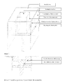
- sketches 1 to 3 show the principle of different versions of a construction space reduction.
- the sketches 1, 2 and 2a show a possibility of space reduction by additional side walls and an essay on the existing construction platform.
- Sketch 1 is a simplified overall view, while the sketches 2 and 2 a simplified represent a sectional view of the space.
- the area available for the construction process is determined by the dimensions of the additional building space walls and the base plate attachment.
- the additional space walls can be firmly connected to each other or be connected to each other by a sliding and locking mechanism. The latter would have the advantage that the size of the space can be made variable. It would then only be the size of the bottom plate attachment adapted to the size specified by the additional space walls.
- Sketch 3 shows a section from the middle of the installation space with a new building platform. Due to the new construction platform, the entire height of the installation space is available. The side walls are to be attached correspondingly over the entire height of the installation space.
- the temperature sensors can be installed just like the heating and cooling elements on the new space wall. For this purpose, the distance between the original building container and the reduction use, can be used.
- the targeted temperature control e.g. a more uniform cooling, but also a targeted temperature control of the components is possible.
- more uniform cooling e.g. a lower tendency to warp can be achieved.
- the lower installation space temperature can be adapted to the materials used. This is a necessary adaptation of the process, especially for materials with a higher melting point. By attaching several, separately controllable heating elements different temperature zones can be adjusted.
- thermocouples If, in addition to the thermocouples, cooling loops are still present, the temperature can be reduced more quickly and thus the time to component removal can be reduced. A faster cooling phase and the associated lower thermal load can also, depending on the material used, be positive for the reuse of the powder.
- the design of the installation space reduction is to be adapted to the respectively required space requirement and is not limited to one size.
- the construction field plate should therefore consist of a material which, in addition to the good temperature resistance, also has a good thermal insulation property. It therefore offer materials such as temperature-resistant polymers, fiber composites or refractory bricks. By a structural design, such as sandwich construction, the heat insulation can be further improved or materials with poor insulation properties, such as metals, are used.
Landscapes
- Engineering & Computer Science (AREA)
- Chemical & Material Sciences (AREA)
- Materials Engineering (AREA)
- Physics & Mathematics (AREA)
- Optics & Photonics (AREA)
- Mechanical Engineering (AREA)
- Manufacturing & Machinery (AREA)
- Powder Metallurgy (AREA)
- Furnace Housings, Linings, Walls, And Ceilings (AREA)
- Furnace Details (AREA)
Abstract
Description
- Lasersinteranlagen sind in verschiedenen Ausführungen, die sich unter anderem im Bauraumvolumen unterscheiden, am Markt verfügbar. Nachteilig bei den verfügbaren Anlagen ist jedoch, dass das Bauraumvolumen nicht variabel auf die jeweiligen Bedürfnisse anzupassen ist. Dies hat zur Folge, dass die benötigte Pulvermenge bei Lasersinteranlagen - auch beim Bau sehr kleiner Teile mit kleiner Stückzahl - nicht reduziert werden kann. Wenn sich das Verhältnis von Bauteil- zu Bauraumvolumen verschlechtert, erhöhen sich die Kosten pro Bauteil Situation aufgrund des zusätzlich benötigten Pulvers.
- Es bestand also die Aufgabe die Nachteile des Standes der Technik zu überwinden. Um die Pulvermenge auf die Bauteilgröße anpassen zu können wurde nun eine Vorrichtung, wie in den Ansprüchen beschrieben, gefunden, die eine Bauraumverkleinerung ermöglicht.
- Die nachfolgenden Skizzen 1 bis 3 zeigen das Prinzip verschiedener Ausführungen einer Bauraumverkleinerung.
Die Skizzen 1, 2 und 2a zeigen eine Möglichkeit der Bauraumverkleinerung durch zusätzliche Seitenwände und einen Aufsatz auf der vorhandenen Bauplattform. Skizze 1 ist dabei eine vereinfachte Gesamtdarstellung, während die Skizzen 2 und 2a vereinfacht eine Schnittdarstellung des Bauraums darstellen. Durch Absenken der Bauplattform senkt sich der starre Aufsatz im gleichen Maße, wodurch die verkleinerte Pulverfläche ebenfalls um die Schichtstärke abgesenkt wird. Die für den Bauvorgang verfügbare Fläche wird durch die Abmaße der zusätzlichen Bauraumwände und des Bodenplattenaufsatz bestimmt. Die zusätzlichen Bauraumwände können fest miteinander verbunden sein oder auch durch eine Schiebe- und Feststellmechanik miteinander verbunden sein. Letzteres hätte den Vorteil, dass die Größe des Bauraums variabel gestaltet werden kann. Es müsste dann nur noch die Größe des Bodenplattenaufsatzes an die durch die zusätzlichen Bauraumwände vorgegebenen Größe angepasst werden. - Skizze 3 zeigt einen Schnitt aus der Mitte des Bauraums mit neuer Bauplattform. Durch die neue Bauplattform steht die gesamte Höhe des Bauraums zur Verfügung. Die Seitenwände sind entsprechend über die gesamte Höhe des Bauraums anzubringen.
- Allen hier dargestellten Möglichkeiten ist gemein, dass die neue Bauraumfläche für die jeweilige Verkleinerung festgelegt ist.
- Durch die Verkleinerung des nutzbaren Bauraums ergibt sich auch die Möglichkeit einer Temperatursteuerung entlang der z-Achse. Die Temperaturfühler können genauso wie die Heiz-und Kühlelemente an der neuen Bauraumwand installiert werden. Hierzu kann der Abstand zwischen dem ursprünglichem Baubehälter und dem Verkleinerungseinsatz, genutzt werden. Die gezielte Temperaturführung, z.B. ein gleichmäßigeres Abkühlen, aber auch ein gezieltes Temperieren der Bauteile ist damit möglich. Durch gleichmäßigeres Abkühlen ist z.B. eine geringere Verzugsneigung erzielbar. Des Weiteren ist die untere Bauraumtemperatur an die verwendeten Materialien anpassbar. Vor allem bei Materialien mit höherem Schmelzpunkt ist dies eine notwendige Anpassung des Prozesses. Durch Anbringen mehrerer, getrennt regelbarer Heizelemente können verschiedene Temperaturzonen eingestellt werden.
- Sind neben den Thermoelementen auch noch Kühlschleifen vorhanden, so kann die Temperatur schneller reduziert und somit die Zeit bis zur Bauteilentnahme reduziert werden. Eine schnellere Abkühlphase und die damit verbundene geringere thermische Belastung kann zudem, je nach verwendetem Material, positiv für die erneute Nutzung des Pulvers sein.
- Die Ausführung der Bauraumverkleinerung ist auf den jeweils erforderlichen Bauraumbedarf anzupassen und ist nicht auf eine Größe limitiert. Die Nutzung der vorhandenen Bauplattform reduziert in der skizzierten Ausführung die zur Verfügung stehende Höhe auf etwas unter die Hälfte der ursprünglich vorhandenen Höhe. Durch Austausch der Bodenplatte kann auch die gesamte Bauraumhöhe genutzt werden. In jedem Fall kann die vorhandene Anlagensteuerung genutzt werden.
- Für die Prozesssicherheit ist eine gute thermische Entkopplung vom oberen Bauraum zum unteren Bauraum von Vorteil. Die Baufeldplatte sollte daher aus einem Material bestehen, welches neben der guten Temperaturfestigkeit auch eine gute Wärmeisolationseigenschaft besitzt. Es bieten sich daher Materialien wie temperaturbeständige Polymere, Faserverbundwerkstoffe oder feuerfeste Steine an. Durch eine konstruktive Gestaltung, wie Sandwichbauweise, kann die Wärmeisolation weiter verbessert werden oder auch Materialien mit schlechter Isolationseigenschaft, wie zum Beispiel Metalle, eingesetzt werden.
Claims (7)
- Vorrichtung zur Verkleinerung des unteren Bauraums einer Lasersinteranlage,
dadurch gekennzeichnet,
dass in eine bestehende Lasersinteranlage zusätzliche oder neue Seitenwände in den unteren Bauraum eingebracht werden. - Vorrichtung nach Anspruch 1,
dadurch gekennzeichnet,
dass auf der vorhandenen Bauplattform der Anlage ein, auf die zusätzlichen bzw. neuen Seitenwände angepasster Aufsatz aufgebracht wird. - Vorrichtung nach Anspruch 1,
dadurch gekennzeichnet,
dass die vorhandene Bauplattform der Anlage durch eine neue Bauplattform, die an die zusätzlichen bzw. neuen Seitenwände angepasst ist, ersetzt wird. - Vorrichtung nach Anspruch 1,
dadurch gekennzeichnet,
dass die zusätzliche Möglichkeit einer, in verschiedenen Bereichen der neuen Seitenwände unterschiedliche oder gleichstarke Erwärmung besteht. - Vorrichtung nach Anspruch 1,
dadurch gekennzeichnet,
dass die zusätzliche Möglichkeit einer, in verschiedenen Bereichen unterschiedliche oder gleichstarke Kühlung besteht. - Vorrichtung nach Anspruch 1,
dadurch gekennzeichnet,
dass durch eine Schiebe- und Feststellmechanik der Bauraum variabel eingestellt werden kann. - Vorrichtung nach Anspruch 1,
dadurch gekennzeichnet,
dass der obere und untere Bauraum durch eine Baufeldplatte getrennt wird, die eine gute Wärmeisolationseigenschaft besitzt
Priority Applications (1)
| Application Number | Priority Date | Filing Date | Title |
|---|---|---|---|
| PL11157014T PL2377672T3 (pl) | 2010-04-17 | 2011-03-04 | Sposób zmniejszenia dolnej przestrzeni konstrukcyjnej urządzenia do spiekania laserowego |
Applications Claiming Priority (1)
| Application Number | Priority Date | Filing Date | Title |
|---|---|---|---|
| DE202010005162U DE202010005162U1 (de) | 2010-04-17 | 2010-04-17 | Vorrichtung zur Verkleinerung des unteren Bauraums einer Lasersinteranlage |
Publications (3)
| Publication Number | Publication Date |
|---|---|
| EP2377672A2 true EP2377672A2 (de) | 2011-10-19 |
| EP2377672A3 EP2377672A3 (de) | 2013-01-02 |
| EP2377672B1 EP2377672B1 (de) | 2021-02-24 |
Family
ID=43049623
Family Applications (1)
| Application Number | Title | Priority Date | Filing Date |
|---|---|---|---|
| EP11157014.9A Active EP2377672B1 (de) | 2010-04-17 | 2011-03-04 | Verfahren zur Verkleinerung des unteren Bauraums einer Lasersinteranlage |
Country Status (7)
| Country | Link |
|---|---|
| US (1) | US20110252618A1 (de) |
| EP (1) | EP2377672B1 (de) |
| JP (1) | JP5780814B2 (de) |
| CN (1) | CN102248163B (de) |
| DE (1) | DE202010005162U1 (de) |
| ES (1) | ES2860696T3 (de) |
| PL (1) | PL2377672T3 (de) |
Cited By (3)
| Publication number | Priority date | Publication date | Assignee | Title |
|---|---|---|---|---|
| DE102015109525A1 (de) * | 2015-06-15 | 2016-12-15 | Cl Schutzrechtsverwaltungs Gmbh | Vorrichtung zum Herstellen von dreidimensionalen Objekten sowie ein zugehöriges Verfahren |
| DE102015212420A1 (de) * | 2015-07-02 | 2017-01-05 | Siemens Aktiengesellschaft | Vorrichtung zur additiven Fertigung eines Bauteils |
| WO2019162190A1 (de) * | 2018-02-21 | 2019-08-29 | Trumpf Laser- Und Systemtechnik Gmbh | Verfahren und maschine zum schnellen inertisieren einer prozesskammer zur additiven fertigung von bauteilen |
Families Citing this family (43)
| Publication number | Priority date | Publication date | Assignee | Title |
|---|---|---|---|---|
| DE102004012682A1 (de) * | 2004-03-16 | 2005-10-06 | Degussa Ag | Verfahren zur Herstellung von dreidimensionalen Objekten mittels Lasertechnik und Auftragen eines Absorbers per Inkjet-Verfahren |
| DE102004020452A1 (de) * | 2004-04-27 | 2005-12-01 | Degussa Ag | Verfahren zur Herstellung von dreidimensionalen Objekten mittels elektromagnetischer Strahlung und Auftragen eines Absorbers per Inkjet-Verfahren |
| DE102011003610A1 (de) | 2011-02-03 | 2012-08-09 | Evonik Degussa Gmbh | Vorrichtung zur besseren Inertisierung von Lasersinteranlagen |
| DE102011014610B3 (de) * | 2011-03-19 | 2012-05-03 | Hochschule Mittweida (Fh) | Einrichtung zum Auftrag von Pulver für additive Fertigungsverfahren |
| DE102011005929A1 (de) * | 2011-03-23 | 2012-09-27 | Bayerische Motoren Werke Aktiengesellschaft | Vorrichtung und Verfahren zum Herstellen eines Bauteils in Schichtbauweise |
| DE102011079521A1 (de) | 2011-07-21 | 2013-01-24 | Evonik Degussa Gmbh | Verbesserte Bauteileigenschaften durch Strahlformung im Laser-Sintern |
| DE102011085154A1 (de) | 2011-10-25 | 2013-04-25 | Evonik Industries Ag | Vorrichtung zur Vermeidung von Ablagerungen an optischen Komponenten im Laser-Sintern |
| GB2503215A (en) * | 2012-06-18 | 2013-12-25 | Rolls Royce Plc | Method of making an object using a deposition control plate |
| US9149870B2 (en) | 2012-09-14 | 2015-10-06 | Aerojet Rocketdyne Of De, Inc. | Additive manufacturing chamber with reduced load |
| US20140077422A1 (en) * | 2012-09-19 | 2014-03-20 | Pratt & Whitney Rocketdyne, Inc. | Reduced build mass additive manufacturing chamber |
| ITVR20120231A1 (it) * | 2012-11-20 | 2014-05-21 | Sisma Spa | Macchina per produrre oggetti tridimensionali a partire da materiali in polvere |
| JP5717900B1 (ja) | 2014-05-15 | 2015-05-13 | 株式会社ソディック | 三次元形状の積層造形物の製造装置 |
| GB201417687D0 (en) * | 2014-10-07 | 2014-11-19 | Renishaw Plc | A module for additive manufacturing apparatus |
| WO2016163861A1 (ko) * | 2015-04-06 | 2016-10-13 | 우정현 | 분말 소결형 프린팅 장치 |
| KR101791543B1 (ko) * | 2015-04-06 | 2017-11-20 | 우정현 | 분말 소결형 프린팅 장치 |
| WO2017044833A1 (en) * | 2015-09-10 | 2017-03-16 | Materialise N.V. | Systems and methods for thermal cycle control in additive manufacturing environments |
| EP4137256A1 (de) * | 2015-10-30 | 2023-02-22 | Seurat Technologies, Inc. | Verfahren und system zur generativen fertigung |
| JP6459912B2 (ja) * | 2015-11-09 | 2019-01-30 | トヨタ自動車株式会社 | 積層造形装置 |
| CN108349163B (zh) * | 2015-12-18 | 2020-12-11 | 惠普发展公司,有限责任合伙企业 | 三维打印的方法、三维打印机以及计算机可读存储介质 |
| WO2017105513A1 (en) * | 2015-12-18 | 2017-06-22 | Hewlett-Packard Development Company, L.P. | Removable cassette for 3d printers |
| US20190009469A1 (en) * | 2016-01-02 | 2019-01-10 | Sd3D Inc. | Heated and adaptive build for 3d printers |
| JP2017132073A (ja) * | 2016-01-26 | 2017-08-03 | 株式会社リコー | 三次元造形装置、三次元造形用チャンバー及び三次元造形方法 |
| DE102016114057A1 (de) * | 2016-07-29 | 2018-02-01 | Cl Schutzrechtsverwaltungs Gmbh | Baukammer für eine Vorrichtung zur additiven Herstellung dreidimensionaler Objekte |
| DE102016219080A1 (de) | 2016-09-30 | 2018-04-05 | Evonik Degussa Gmbh | Polyamidpulver für selektive Sinterverfahren |
| CN107952956B (zh) * | 2016-10-16 | 2019-10-15 | 北京煜鼎增材制造研究院有限公司 | 用于激光增材制造的气氛保护系统及激光增材制造设备 |
| KR20180052225A (ko) * | 2016-11-10 | 2018-05-18 | 현대자동차주식회사 | 3d 프린터의 가공챔버 분할 장치 |
| US20190126544A1 (en) * | 2016-11-29 | 2019-05-02 | Hewlett-Packard Development Company, L.P. | Accessory for three-dimensional printing |
| DE102017110650A1 (de) * | 2017-05-16 | 2018-11-22 | Ald Vacuum Technologies Gmbh | Verfahren und Vorrichtung für die additive Herstellung von Werkstücken |
| JP6858658B2 (ja) * | 2017-06-29 | 2021-04-14 | 三菱電機株式会社 | 積層造形体の製造装置および製造方法 |
| KR101990308B1 (ko) * | 2017-08-18 | 2019-06-18 | (주)센트롤 | 삼차원 프린터 |
| US11571743B2 (en) | 2017-11-13 | 2023-02-07 | General Electric Company | Systems and methods for additive manufacturing |
| EP3501695A1 (de) | 2017-12-22 | 2019-06-26 | Evonik Degussa GmbH | Vorrichtung zur schichtweisen herstellung von dreidimensionalen objekten sowie herstellungsverfahren dazu |
| US10065242B1 (en) * | 2018-03-01 | 2018-09-04 | King Saud University | Adjustable build envelope for powder bed fusion machines |
| US11712848B2 (en) * | 2018-09-27 | 2023-08-01 | Eos Of North America, Inc. | Modifying a building space in an apparatus for powder bed additive manufacturing a three-dimensional object |
| US10994483B2 (en) * | 2018-10-01 | 2021-05-04 | Eos Of North America, Inc. | Dual roller assembly for spreading material in additive manufacturing apparatus |
| DE102018007813A1 (de) * | 2018-10-04 | 2020-04-09 | Ralf Lampalzer | Verfahren und Vorrichtung zur Anpassung der Bauraumgeometrie bei Selektivem Laserschmelzen ode Selektivem Lasersintern |
| EP3632654A1 (de) * | 2018-10-04 | 2020-04-08 | Ralf Lampalzer | Vorrichtung und verfahren zum selektiven laserschmelzen und/oder lasersintern |
| EP3698956A1 (de) | 2019-02-21 | 2020-08-26 | Evonik Operations GmbH | Verfahren zur oberflächenbearbeitung von polymeren dreidimensionalen objekten |
| US12162074B2 (en) | 2020-11-25 | 2024-12-10 | Lawrence Livermore National Security, Llc | System and method for large-area pulsed laser melting of metallic powder in a laser powder bed fusion application |
| CN113352609A (zh) * | 2021-06-28 | 2021-09-07 | 北京工业大学 | 一种光固化陶瓷成型设备可选幅面成型台 |
| DE102021119465A1 (de) | 2021-07-27 | 2023-02-02 | Airbus Operations Gmbh | Verfahren und Vorrichtung zur additiven Fertigung eines Bauteils innerhalb einer Aufnahmeeinheit unter Verwendung eines pulverartigen Materials |
| JP7279234B1 (ja) * | 2022-04-27 | 2023-05-22 | 株式会社ソディック | 積層造形装置および積層造形装置用の小領域造形ユニット |
| US12226949B2 (en) | 2022-05-25 | 2025-02-18 | The Boeing Company | Model based supporting spokes activation to aid 3D printing |
Citations (1)
| Publication number | Priority date | Publication date | Assignee | Title |
|---|---|---|---|---|
| JP2007030303A (ja) | 2005-07-26 | 2007-02-08 | Aspect Inc | 粉末焼結積層造形装置 |
Family Cites Families (40)
| Publication number | Priority date | Publication date | Assignee | Title |
|---|---|---|---|---|
| US3521849A (en) * | 1966-10-22 | 1970-07-28 | Schloemann Ag | Continuous metal-casting mold |
| US4273581A (en) * | 1978-04-07 | 1981-06-16 | Inoue-Japax Research Incorporated | Sintering method |
| JPS57112998A (en) * | 1980-12-29 | 1982-07-14 | Yoshitsuka Seiki:Kk | Die set exchanging device for powder molding press |
| JPS57112997A (en) * | 1980-12-29 | 1982-07-14 | Yoshitsuka Seiki:Kk | Die set exchanging device for powder molding press |
| JPS5930519B2 (ja) * | 1980-12-29 | 1984-07-27 | 株式会社ヨシツカ精機 | 粉末成形プレスのダイセット交換装置 |
| JPS60116702A (ja) * | 1983-11-29 | 1985-06-24 | Kobe Steel Ltd | 高能率熱間静水圧成形方法および装置 |
| JPH0825077B2 (ja) * | 1990-12-28 | 1996-03-13 | 株式会社ヨシツカ精機 | 粉末成形プレスのツールセットの交換装置 |
| US5393482A (en) * | 1993-10-20 | 1995-02-28 | United Technologies Corporation | Method for performing multiple beam laser sintering employing focussed and defocussed laser beams |
| FR2713541B1 (fr) * | 1993-12-09 | 1997-04-30 | Laser Int Sa | Procédé et installation pour la fabrication de pièces par phototransformation de matière. |
| US5731013A (en) * | 1995-09-13 | 1998-03-24 | The Whitaker Corporation | Reconfigurable mold having travelling separator assist |
| DE19846478C5 (de) * | 1998-10-09 | 2004-10-14 | Eos Gmbh Electro Optical Systems | Laser-Sintermaschine |
| JP4015796B2 (ja) * | 1999-03-31 | 2007-11-28 | Spsシンテックス株式会社 | 自動パルス通電加圧焼結方法及びそのシステム |
| NL1014262C2 (nl) * | 2000-02-02 | 2001-08-03 | Beheermij De Boer Nijmegen Bv | Vormbak met verwisselbaar vormbakdeel. |
| JP2001334580A (ja) * | 2000-05-24 | 2001-12-04 | Minolta Co Ltd | 三次元造形装置および三次元造形方法 |
| US6682688B1 (en) * | 2000-06-16 | 2004-01-27 | Matsushita Electric Works, Ltd. | Method of manufacturing a three-dimensional object |
| DE10047615A1 (de) * | 2000-09-26 | 2002-04-25 | Generis Gmbh | Wechselbehälter |
| US7220365B2 (en) * | 2001-08-13 | 2007-05-22 | New Qu Energy Ltd. | Devices using a medium having a high heat transfer rate |
| US6822194B2 (en) * | 2002-05-29 | 2004-11-23 | The Boeing Company | Thermocouple control system for selective laser sintering part bed temperature control |
| US6815636B2 (en) * | 2003-04-09 | 2004-11-09 | 3D Systems, Inc. | Sintering using thermal image feedback |
| JP4141379B2 (ja) * | 2003-12-12 | 2008-08-27 | 日立造船株式会社 | 三次元物体の造形方法および造形装置 |
| US7034246B2 (en) * | 2004-08-10 | 2006-04-25 | The Boeing Company | Selective laser sintering reduced volume feed mechanism |
| US7357629B2 (en) * | 2005-03-23 | 2008-04-15 | 3D Systems, Inc. | Apparatus and method for aligning a removable build chamber within a process chamber |
| US7790096B2 (en) * | 2005-03-31 | 2010-09-07 | 3D Systems, Inc. | Thermal management system for a removable build chamber for use with a laser sintering system |
| DE102005030854B3 (de) * | 2005-07-01 | 2007-03-08 | Eos Gmbh Electro Optical Systems | Vorrichtung zum Herstellen eines dreidimensionalen Objektes |
| JP4917381B2 (ja) * | 2006-08-09 | 2012-04-18 | 株式会社アスペクト | 粉末焼結積層造形装置及び粉末焼結積層造形方法 |
| DE102006055075A1 (de) * | 2006-11-22 | 2008-05-29 | Eos Gmbh Electro Optical Systems | Vorrichtung zum schichtweisen Herstellen eines dreidimensionalen Objekts |
| DE102006055052A1 (de) * | 2006-11-22 | 2008-05-29 | Eos Gmbh Electro Optical Systems | Vorrichtung zum schichtweisen Herstellen eines dreidimensionalen Objekts |
| DE102006055077A1 (de) * | 2006-11-22 | 2008-05-29 | Eos Gmbh Electro Optical Systems | Vorrichtung zum schichtweisen Herstellen eines dreidimensionalen Objekts und Verfahren zum Einsetzen bzw. Entnehmen eines Behälters |
| DE102006055054A1 (de) * | 2006-11-22 | 2008-05-29 | Eos Gmbh Electro Optical Systems | Vorrichtung zum schichtweisen Herstellen eines dreidimensionalen Objekts |
| DE102006055073A1 (de) * | 2006-11-22 | 2008-05-29 | Eos Gmbh Electro Optical Systems | Vorrichtung und Verfahren zum schichtweisen Herstellen eines dreidimensionalen Objekts |
| DE102006055056A1 (de) * | 2006-11-22 | 2008-05-29 | Eos Gmbh Electro Optical Systems | Beschichter zum Auftragen einer Schicht eines pulverförmigen Aufbaumaterials in einer Vorrichtung zum schichtweisen Herstellen eines dreidimensionalen Objekts |
| DE102006055076A1 (de) * | 2006-11-22 | 2008-05-29 | Eos Gmbh Electro Optical Systems | Baubehälter für eine Vorrichtung zum schichtweisen Herstellen eines dreidimensionalen Objekts |
| US7968044B2 (en) * | 2007-04-30 | 2011-06-28 | Spraying Systems Co. | Sinter processing system |
| JP4258571B2 (ja) * | 2007-05-14 | 2009-04-30 | パナソニック電工株式会社 | 三次元形状造形物の製造方法及び製造装置 |
| US8206637B2 (en) * | 2008-10-14 | 2012-06-26 | The Boeing Company | Geometry adaptive laser sintering system |
| US8007708B2 (en) * | 2008-12-12 | 2011-08-30 | Innoventor Incorporated | Apparatus and methods for automating movement of mold drawers |
| US20100155985A1 (en) * | 2008-12-18 | 2010-06-24 | 3D Systems, Incorporated | Apparatus and Method for Cooling Part Cake in Laser Sintering |
| JP5452072B2 (ja) * | 2009-05-07 | 2014-03-26 | 株式会社エイチ・ティー・エル | 電子ビーム造形方法 |
| DE102009020987A1 (de) * | 2009-05-12 | 2010-11-18 | Cl Schutzrechtsverwaltungs Gmbh | Vorrichtung zur Herstellung von dreidimensionalen Objekten |
| US9522501B2 (en) * | 2010-09-21 | 2016-12-20 | The Boeing Company | Continuous linear production in a selective laser sintering system |
-
2010
- 2010-04-17 DE DE202010005162U patent/DE202010005162U1/de not_active Expired - Lifetime
-
2011
- 2011-03-04 EP EP11157014.9A patent/EP2377672B1/de active Active
- 2011-03-04 ES ES11157014T patent/ES2860696T3/es active Active
- 2011-03-04 PL PL11157014T patent/PL2377672T3/pl unknown
- 2011-04-14 US US13/086,860 patent/US20110252618A1/en not_active Abandoned
- 2011-04-14 CN CN201110109410.6A patent/CN102248163B/zh active Active
- 2011-04-18 JP JP2011092322A patent/JP5780814B2/ja active Active
Patent Citations (1)
| Publication number | Priority date | Publication date | Assignee | Title |
|---|---|---|---|---|
| JP2007030303A (ja) | 2005-07-26 | 2007-02-08 | Aspect Inc | 粉末焼結積層造形装置 |
Cited By (4)
| Publication number | Priority date | Publication date | Assignee | Title |
|---|---|---|---|---|
| DE102015109525A1 (de) * | 2015-06-15 | 2016-12-15 | Cl Schutzrechtsverwaltungs Gmbh | Vorrichtung zum Herstellen von dreidimensionalen Objekten sowie ein zugehöriges Verfahren |
| US10821513B2 (en) | 2015-06-15 | 2020-11-03 | Concept Laser Gmbh | Device for producing three-dimensional objects and a corresponding method |
| DE102015212420A1 (de) * | 2015-07-02 | 2017-01-05 | Siemens Aktiengesellschaft | Vorrichtung zur additiven Fertigung eines Bauteils |
| WO2019162190A1 (de) * | 2018-02-21 | 2019-08-29 | Trumpf Laser- Und Systemtechnik Gmbh | Verfahren und maschine zum schnellen inertisieren einer prozesskammer zur additiven fertigung von bauteilen |
Also Published As
| Publication number | Publication date |
|---|---|
| CN102248163A (zh) | 2011-11-23 |
| DE202010005162U1 (de) | 2010-11-04 |
| JP2011225994A (ja) | 2011-11-10 |
| PL2377672T3 (pl) | 2021-07-26 |
| EP2377672B1 (de) | 2021-02-24 |
| JP5780814B2 (ja) | 2015-09-16 |
| US20110252618A1 (en) | 2011-10-20 |
| ES2860696T3 (es) | 2021-10-05 |
| EP2377672A3 (de) | 2013-01-02 |
| CN102248163B (zh) | 2016-06-22 |
Similar Documents
| Publication | Publication Date | Title |
|---|---|---|
| EP2377672A2 (de) | Vorrichtung zur Verkleinerung des unteren Bauraums einer Lasersinteranlage | |
| EP2313254B1 (de) | Wechselrahmen für eine vorrichtung zum herstellen eines dreidimensionalen objekts und vorrichtung zum herstellen eines dreidimensionalen objekts mit einem solchen wechselrahmen | |
| EP3083026A1 (de) | Verfahren zur herstellung von schleifmittel | |
| EP3655234A1 (de) | Verfahren und vorrichtung zum herstellen von 3d-formteilen mit spektrumswandler | |
| DE102007003357A1 (de) | Verfahren zum Verbinden eines thermoplastischen Materials mit einem Faserverbundmaterial | |
| DE10323591A1 (de) | Verfahren und Vorrichtung zur Erzeugung eines Gases aus einem Sublimationsgut | |
| EP2833697B1 (de) | Kochfeldvorrichtung | |
| DE2702210C3 (de) | Filterkörper zur Feinstabscheidung von Nebel- und Feststoffaerosolen aus Gasen, insbesondere Druckluft sowie Verfahren zur Herstellung solcher Filterkörper | |
| EP2942406B1 (de) | Feuerfestes keramisches Gasspülelement | |
| DE19834542A1 (de) | Verfahren zur Herstellung von Verstärkungsfasern enthaltenden Körpern | |
| DE102014223779B4 (de) | Wärmeübertragerelement, Verfahren zur Herstellung und Wärmeübertrager | |
| WO2011104094A1 (de) | Vorrichtung zum erwärmen von flüssigkeiten | |
| DE2452386A1 (de) | Verfahren und vorrichtung zur behandlung von dispersionen | |
| DE102013104102A1 (de) | Filtereinrichtung | |
| EP1274500B1 (de) | Vorrichtung bestehend aus einer verbundmembrane und aus einer vorrichtung für eine energiezufuhr oder energieableitung | |
| DE102005055955B3 (de) | Solarempfänger | |
| DE69209154T2 (de) | Beschickungsanlage für das Tragen von Werkstücken in Ofen | |
| DE69902950T2 (de) | Verdichtung poröser körper | |
| WO2015158720A1 (de) | Sensorelement, sensormodul, messanordnung und abgasrückführsystem mit einem solchen sensorelement sowie herstellungsverfahren | |
| DE202009010938U1 (de) | Verbesserter Werkstückträger | |
| EP3610171B1 (de) | Reibbelagkörper | |
| DE2211449C3 (de) | Verfahren zum Herstellen langgestreckter Körner aus pulverförmigen Substanzen und Vorrichtung zur Durchführung des Verfahrens | |
| DE102012202196A1 (de) | Deckelgriff eines Deckels | |
| DE60107755T2 (de) | Mit Metallsilizid imprägniertes Verbundmaterial und Verfahren zu dessen Herstellung | |
| EP3484244B1 (de) | Induktionsgargerätevorrichtung |
Legal Events
| Date | Code | Title | Description |
|---|---|---|---|
| 17P | Request for examination filed |
Effective date: 20110304 |
|
| AK | Designated contracting states |
Kind code of ref document: A2 Designated state(s): AL AT BE BG CH CY CZ DE DK EE ES FI FR GB GR HR HU IE IS IT LI LT LU LV MC MK MT NL NO PL PT RO RS SE SI SK SM TR |
|
| AX | Request for extension of the european patent |
Extension state: BA ME |
|
| PUAI | Public reference made under article 153(3) epc to a published international application that has entered the european phase |
Free format text: ORIGINAL CODE: 0009012 |
|
| PUAL | Search report despatched |
Free format text: ORIGINAL CODE: 0009013 |
|
| AK | Designated contracting states |
Kind code of ref document: A3 Designated state(s): AL AT BE BG CH CY CZ DE DK EE ES FI FR GB GR HR HU IE IS IT LI LT LU LV MC MK MT NL NO PL PT RO RS SE SI SK SM TR |
|
| AX | Request for extension of the european patent |
Extension state: BA ME |
|
| RIC1 | Information provided on ipc code assigned before grant |
Ipc: B29C 67/00 20060101AFI20121128BHEP |
|
| 17Q | First examination report despatched |
Effective date: 20130813 |
|
| TPAC | Observations filed by third parties |
Free format text: ORIGINAL CODE: EPIDOSNTIPA |
|
| STAA | Information on the status of an ep patent application or granted ep patent |
Free format text: STATUS: EXAMINATION IS IN PROGRESS |
|
| RAP1 | Party data changed (applicant data changed or rights of an application transferred) |
Owner name: EVONIK DEGUSSA GMBH |
|
| RAP1 | Party data changed (applicant data changed or rights of an application transferred) |
Owner name: EVONIK OPERATIONS GMBH |
|
| REG | Reference to a national code |
Ref country code: DE Ref legal event code: R079 Ref document number: 502011017061 Country of ref document: DE Free format text: PREVIOUS MAIN CLASS: B29C0067000000 Ipc: B29C0064153000 |
|
| RIC1 | Information provided on ipc code assigned before grant |
Ipc: B22F 3/105 20060101ALI20200721BHEP Ipc: B33Y 10/00 20150101ALI20200721BHEP Ipc: B33Y 30/00 20150101ALI20200721BHEP Ipc: B29C 64/25 20170101ALI20200721BHEP Ipc: B29C 64/153 20170101AFI20200721BHEP |
|
| GRAP | Despatch of communication of intention to grant a patent |
Free format text: ORIGINAL CODE: EPIDOSNIGR1 |
|
| STAA | Information on the status of an ep patent application or granted ep patent |
Free format text: STATUS: GRANT OF PATENT IS INTENDED |
|
| INTG | Intention to grant announced |
Effective date: 20200924 |
|
| RIN1 | Information on inventor provided before grant (corrected) |
Inventor name: ALTKEMPER, STEFAN Inventor name: DIEKMANN, WOLFGANG Inventor name: GREBE, MAIK |
|
| GRAS | Grant fee paid |
Free format text: ORIGINAL CODE: EPIDOSNIGR3 |
|
| GRAA | (expected) grant |
Free format text: ORIGINAL CODE: 0009210 |
|
| STAA | Information on the status of an ep patent application or granted ep patent |
Free format text: STATUS: THE PATENT HAS BEEN GRANTED |
|
| AK | Designated contracting states |
Kind code of ref document: B1 Designated state(s): AL AT BE BG CH CY CZ DE DK EE ES FI FR GB GR HR HU IE IS IT LI LT LU LV MC MK MT NL NO PL PT RO RS SE SI SK SM TR |
|
| REG | Reference to a national code |
Ref country code: GB Ref legal event code: FG4D Free format text: NOT ENGLISH |
|
| REG | Reference to a national code |
Ref country code: CH Ref legal event code: EP |
|
| REG | Reference to a national code |
Ref country code: DE Ref legal event code: R096 Ref document number: 502011017061 Country of ref document: DE |
|
| REG | Reference to a national code |
Ref country code: AT Ref legal event code: REF Ref document number: 1363905 Country of ref document: AT Kind code of ref document: T Effective date: 20210315 |
|
| REG | Reference to a national code |
Ref country code: IE Ref legal event code: FG4D Free format text: LANGUAGE OF EP DOCUMENT: GERMAN |
|
| REG | Reference to a national code |
Ref country code: LT Ref legal event code: MG9D |
|
| REG | Reference to a national code |
Ref country code: NL Ref legal event code: MP Effective date: 20210224 |
|
| PG25 | Lapsed in a contracting state [announced via postgrant information from national office to epo] |
Ref country code: FI Free format text: LAPSE BECAUSE OF FAILURE TO SUBMIT A TRANSLATION OF THE DESCRIPTION OR TO PAY THE FEE WITHIN THE PRESCRIBED TIME-LIMIT Effective date: 20210224 Ref country code: HR Free format text: LAPSE BECAUSE OF FAILURE TO SUBMIT A TRANSLATION OF THE DESCRIPTION OR TO PAY THE FEE WITHIN THE PRESCRIBED TIME-LIMIT Effective date: 20210224 Ref country code: GR Free format text: LAPSE BECAUSE OF FAILURE TO SUBMIT A TRANSLATION OF THE DESCRIPTION OR TO PAY THE FEE WITHIN THE PRESCRIBED TIME-LIMIT Effective date: 20210525 Ref country code: LT Free format text: LAPSE BECAUSE OF FAILURE TO SUBMIT A TRANSLATION OF THE DESCRIPTION OR TO PAY THE FEE WITHIN THE PRESCRIBED TIME-LIMIT Effective date: 20210224 Ref country code: NO Free format text: LAPSE BECAUSE OF FAILURE TO SUBMIT A TRANSLATION OF THE DESCRIPTION OR TO PAY THE FEE WITHIN THE PRESCRIBED TIME-LIMIT Effective date: 20210524 Ref country code: BG Free format text: LAPSE BECAUSE OF FAILURE TO SUBMIT A TRANSLATION OF THE DESCRIPTION OR TO PAY THE FEE WITHIN THE PRESCRIBED TIME-LIMIT Effective date: 20210524 Ref country code: PT Free format text: LAPSE BECAUSE OF FAILURE TO SUBMIT A TRANSLATION OF THE DESCRIPTION OR TO PAY THE FEE WITHIN THE PRESCRIBED TIME-LIMIT Effective date: 20210624 |
|
| PG25 | Lapsed in a contracting state [announced via postgrant information from national office to epo] |
Ref country code: RS Free format text: LAPSE BECAUSE OF FAILURE TO SUBMIT A TRANSLATION OF THE DESCRIPTION OR TO PAY THE FEE WITHIN THE PRESCRIBED TIME-LIMIT Effective date: 20210224 Ref country code: NL Free format text: LAPSE BECAUSE OF FAILURE TO SUBMIT A TRANSLATION OF THE DESCRIPTION OR TO PAY THE FEE WITHIN THE PRESCRIBED TIME-LIMIT Effective date: 20210224 Ref country code: LV Free format text: LAPSE BECAUSE OF FAILURE TO SUBMIT A TRANSLATION OF THE DESCRIPTION OR TO PAY THE FEE WITHIN THE PRESCRIBED TIME-LIMIT Effective date: 20210224 Ref country code: SE Free format text: LAPSE BECAUSE OF FAILURE TO SUBMIT A TRANSLATION OF THE DESCRIPTION OR TO PAY THE FEE WITHIN THE PRESCRIBED TIME-LIMIT Effective date: 20210224 |
|
| PG25 | Lapsed in a contracting state [announced via postgrant information from national office to epo] |
Ref country code: IS Free format text: LAPSE BECAUSE OF FAILURE TO SUBMIT A TRANSLATION OF THE DESCRIPTION OR TO PAY THE FEE WITHIN THE PRESCRIBED TIME-LIMIT Effective date: 20210624 |
|
| PG25 | Lapsed in a contracting state [announced via postgrant information from national office to epo] |
Ref country code: SM Free format text: LAPSE BECAUSE OF FAILURE TO SUBMIT A TRANSLATION OF THE DESCRIPTION OR TO PAY THE FEE WITHIN THE PRESCRIBED TIME-LIMIT Effective date: 20210224 Ref country code: EE Free format text: LAPSE BECAUSE OF FAILURE TO SUBMIT A TRANSLATION OF THE DESCRIPTION OR TO PAY THE FEE WITHIN THE PRESCRIBED TIME-LIMIT Effective date: 20210224 |
|
| REG | Reference to a national code |
Ref country code: DE Ref legal event code: R097 Ref document number: 502011017061 Country of ref document: DE |
|
| PG25 | Lapsed in a contracting state [announced via postgrant information from national office to epo] |
Ref country code: DK Free format text: LAPSE BECAUSE OF FAILURE TO SUBMIT A TRANSLATION OF THE DESCRIPTION OR TO PAY THE FEE WITHIN THE PRESCRIBED TIME-LIMIT Effective date: 20210224 Ref country code: MC Free format text: LAPSE BECAUSE OF FAILURE TO SUBMIT A TRANSLATION OF THE DESCRIPTION OR TO PAY THE FEE WITHIN THE PRESCRIBED TIME-LIMIT Effective date: 20210224 Ref country code: SK Free format text: LAPSE BECAUSE OF FAILURE TO SUBMIT A TRANSLATION OF THE DESCRIPTION OR TO PAY THE FEE WITHIN THE PRESCRIBED TIME-LIMIT Effective date: 20210224 Ref country code: RO Free format text: LAPSE BECAUSE OF FAILURE TO SUBMIT A TRANSLATION OF THE DESCRIPTION OR TO PAY THE FEE WITHIN THE PRESCRIBED TIME-LIMIT Effective date: 20210224 |
|
| PLBE | No opposition filed within time limit |
Free format text: ORIGINAL CODE: 0009261 |
|
| STAA | Information on the status of an ep patent application or granted ep patent |
Free format text: STATUS: NO OPPOSITION FILED WITHIN TIME LIMIT |
|
| PG25 | Lapsed in a contracting state [announced via postgrant information from national office to epo] |
Ref country code: IE Free format text: LAPSE BECAUSE OF NON-PAYMENT OF DUE FEES Effective date: 20210304 Ref country code: LU Free format text: LAPSE BECAUSE OF NON-PAYMENT OF DUE FEES Effective date: 20210304 Ref country code: AL Free format text: LAPSE BECAUSE OF FAILURE TO SUBMIT A TRANSLATION OF THE DESCRIPTION OR TO PAY THE FEE WITHIN THE PRESCRIBED TIME-LIMIT Effective date: 20210224 |
|
| 26N | No opposition filed |
Effective date: 20211125 |
|
| PG25 | Lapsed in a contracting state [announced via postgrant information from national office to epo] |
Ref country code: SI Free format text: LAPSE BECAUSE OF FAILURE TO SUBMIT A TRANSLATION OF THE DESCRIPTION OR TO PAY THE FEE WITHIN THE PRESCRIBED TIME-LIMIT Effective date: 20210224 |
|
| REG | Reference to a national code |
Ref country code: AT Ref legal event code: MM01 Ref document number: 1363905 Country of ref document: AT Kind code of ref document: T Effective date: 20210304 |
|
| PG25 | Lapsed in a contracting state [announced via postgrant information from national office to epo] |
Ref country code: IS Free format text: LAPSE BECAUSE OF FAILURE TO SUBMIT A TRANSLATION OF THE DESCRIPTION OR TO PAY THE FEE WITHIN THE PRESCRIBED TIME-LIMIT Effective date: 20210624 |
|
| PG25 | Lapsed in a contracting state [announced via postgrant information from national office to epo] |
Ref country code: AT Free format text: LAPSE BECAUSE OF NON-PAYMENT OF DUE FEES Effective date: 20210304 |
|
| PG25 | Lapsed in a contracting state [announced via postgrant information from national office to epo] |
Ref country code: HU Free format text: LAPSE BECAUSE OF FAILURE TO SUBMIT A TRANSLATION OF THE DESCRIPTION OR TO PAY THE FEE WITHIN THE PRESCRIBED TIME-LIMIT; INVALID AB INITIO Effective date: 20110304 Ref country code: CY Free format text: LAPSE BECAUSE OF FAILURE TO SUBMIT A TRANSLATION OF THE DESCRIPTION OR TO PAY THE FEE WITHIN THE PRESCRIBED TIME-LIMIT Effective date: 20210224 |
|
| P01 | Opt-out of the competence of the unified patent court (upc) registered |
Effective date: 20230524 |
|
| PG25 | Lapsed in a contracting state [announced via postgrant information from national office to epo] |
Ref country code: MK Free format text: LAPSE BECAUSE OF FAILURE TO SUBMIT A TRANSLATION OF THE DESCRIPTION OR TO PAY THE FEE WITHIN THE PRESCRIBED TIME-LIMIT Effective date: 20210224 |
|
| PG25 | Lapsed in a contracting state [announced via postgrant information from national office to epo] |
Ref country code: TR Free format text: LAPSE BECAUSE OF FAILURE TO SUBMIT A TRANSLATION OF THE DESCRIPTION OR TO PAY THE FEE WITHIN THE PRESCRIBED TIME-LIMIT Effective date: 20210224 |
|
| PG25 | Lapsed in a contracting state [announced via postgrant information from national office to epo] |
Ref country code: MT Free format text: LAPSE BECAUSE OF FAILURE TO SUBMIT A TRANSLATION OF THE DESCRIPTION OR TO PAY THE FEE WITHIN THE PRESCRIBED TIME-LIMIT Effective date: 20210224 |
|
| PGFP | Annual fee paid to national office [announced via postgrant information from national office to epo] |
Ref country code: ES Payment date: 20250425 Year of fee payment: 15 |
|
| PGFP | Annual fee paid to national office [announced via postgrant information from national office to epo] |
Ref country code: CH Payment date: 20250401 Year of fee payment: 15 |
|
| REG | Reference to a national code |
Ref country code: CH Ref legal event code: U11 Free format text: ST27 STATUS EVENT CODE: U-0-0-U10-U11 (AS PROVIDED BY THE NATIONAL OFFICE) Effective date: 20260401 |
|
| PGFP | Annual fee paid to national office [announced via postgrant information from national office to epo] |
Ref country code: GB Payment date: 20260324 Year of fee payment: 16 |
|
| PGFP | Annual fee paid to national office [announced via postgrant information from national office to epo] |
Ref country code: DE Payment date: 20260319 Year of fee payment: 16 |
|
| PGFP | Annual fee paid to national office [announced via postgrant information from national office to epo] |
Ref country code: BE Payment date: 20260319 Year of fee payment: 16 Ref country code: IT Payment date: 20260324 Year of fee payment: 16 |
|
| PGFP | Annual fee paid to national office [announced via postgrant information from national office to epo] |
Ref country code: FR Payment date: 20260320 Year of fee payment: 16 |
|
| PGFP | Annual fee paid to national office [announced via postgrant information from national office to epo] |
Ref country code: CZ Payment date: 20260224 Year of fee payment: 16 |
|
| PGFP | Annual fee paid to national office [announced via postgrant information from national office to epo] |
Ref country code: PL Payment date: 20260223 Year of fee payment: 16 |