EP2377710A2 - Machine de travail hybride dotée d'une fonction de protection de la batterie - Google Patents
Machine de travail hybride dotée d'une fonction de protection de la batterie Download PDFInfo
- Publication number
- EP2377710A2 EP2377710A2 EP11162251A EP11162251A EP2377710A2 EP 2377710 A2 EP2377710 A2 EP 2377710A2 EP 11162251 A EP11162251 A EP 11162251A EP 11162251 A EP11162251 A EP 11162251A EP 2377710 A2 EP2377710 A2 EP 2377710A2
- Authority
- EP
- European Patent Office
- Prior art keywords
- battery
- charging
- working
- period
- map
- Prior art date
- Legal status (The legal status is an assumption and is not a legal conclusion. Google has not performed a legal analysis and makes no representation as to the accuracy of the status listed.)
- Granted
Links
Images


Classifications
-
- B—PERFORMING OPERATIONS; TRANSPORTING
- B60—VEHICLES IN GENERAL
- B60K—ARRANGEMENT OR MOUNTING OF PROPULSION UNITS OR OF TRANSMISSIONS IN VEHICLES; ARRANGEMENT OR MOUNTING OF PLURAL DIVERSE PRIME-MOVERS IN VEHICLES; AUXILIARY DRIVES FOR VEHICLES; INSTRUMENTATION OR DASHBOARDS FOR VEHICLES; ARRANGEMENTS IN CONNECTION WITH COOLING, AIR INTAKE, GAS EXHAUST OR FUEL SUPPLY OF PROPULSION UNITS IN VEHICLES
- B60K6/00—Arrangement or mounting of plural diverse prime-movers for mutual or common propulsion, e.g. hybrid propulsion systems comprising electric motors and internal combustion engines
- B60K6/20—Arrangement or mounting of plural diverse prime-movers for mutual or common propulsion, e.g. hybrid propulsion systems comprising electric motors and internal combustion engines the prime-movers consisting of electric motors and internal combustion engines, e.g. HEVs
- B60K6/42—Arrangement or mounting of plural diverse prime-movers for mutual or common propulsion, e.g. hybrid propulsion systems comprising electric motors and internal combustion engines the prime-movers consisting of electric motors and internal combustion engines, e.g. HEVs characterised by the architecture of the hybrid electric vehicle
- B60K6/48—Parallel type
-
- B—PERFORMING OPERATIONS; TRANSPORTING
- B60—VEHICLES IN GENERAL
- B60W—CONJOINT CONTROL OF VEHICLE SUB-UNITS OF DIFFERENT TYPE OR DIFFERENT FUNCTION; CONTROL SYSTEMS SPECIALLY ADAPTED FOR HYBRID VEHICLES; ROAD VEHICLE DRIVE CONTROL SYSTEMS FOR PURPOSES NOT RELATED TO THE CONTROL OF A PARTICULAR SUB-UNIT
- B60W10/00—Conjoint control of vehicle sub-units of different type or different function
- B60W10/24—Conjoint control of vehicle sub-units of different type or different function including control of energy storage means
- B60W10/26—Conjoint control of vehicle sub-units of different type or different function including control of energy storage means for electrical energy, e.g. batteries or capacitors
-
- B—PERFORMING OPERATIONS; TRANSPORTING
- B60—VEHICLES IN GENERAL
- B60W—CONJOINT CONTROL OF VEHICLE SUB-UNITS OF DIFFERENT TYPE OR DIFFERENT FUNCTION; CONTROL SYSTEMS SPECIALLY ADAPTED FOR HYBRID VEHICLES; ROAD VEHICLE DRIVE CONTROL SYSTEMS FOR PURPOSES NOT RELATED TO THE CONTROL OF A PARTICULAR SUB-UNIT
- B60W10/00—Conjoint control of vehicle sub-units of different type or different function
- B60W10/30—Conjoint control of vehicle sub-units of different type or different function including control of auxiliary equipment, e.g. air-conditioning compressors or oil pumps
-
- B—PERFORMING OPERATIONS; TRANSPORTING
- B60—VEHICLES IN GENERAL
- B60W—CONJOINT CONTROL OF VEHICLE SUB-UNITS OF DIFFERENT TYPE OR DIFFERENT FUNCTION; CONTROL SYSTEMS SPECIALLY ADAPTED FOR HYBRID VEHICLES; ROAD VEHICLE DRIVE CONTROL SYSTEMS FOR PURPOSES NOT RELATED TO THE CONTROL OF A PARTICULAR SUB-UNIT
- B60W20/00—Control systems specially adapted for hybrid vehicles
- B60W20/10—Controlling the power contribution of each of the prime movers to meet required power demand
- B60W20/13—Controlling the power contribution of each of the prime movers to meet required power demand in order to stay within battery power input or output limits; in order to prevent overcharging or battery depletion
-
- B—PERFORMING OPERATIONS; TRANSPORTING
- B60—VEHICLES IN GENERAL
- B60W—CONJOINT CONTROL OF VEHICLE SUB-UNITS OF DIFFERENT TYPE OR DIFFERENT FUNCTION; CONTROL SYSTEMS SPECIALLY ADAPTED FOR HYBRID VEHICLES; ROAD VEHICLE DRIVE CONTROL SYSTEMS FOR PURPOSES NOT RELATED TO THE CONTROL OF A PARTICULAR SUB-UNIT
- B60W30/00—Purposes of road vehicle drive control systems not related to the control of a particular sub-unit, e.g. of systems using conjoint control of vehicle sub-units
- B60W30/18—Propelling the vehicle
- B60W30/18009—Propelling the vehicle related to particular drive situations
- B60W30/18054—Propelling the vehicle related to particular drive situations at stand still, e.g. engine in idling state
-
- B—PERFORMING OPERATIONS; TRANSPORTING
- B60—VEHICLES IN GENERAL
- B60W—CONJOINT CONTROL OF VEHICLE SUB-UNITS OF DIFFERENT TYPE OR DIFFERENT FUNCTION; CONTROL SYSTEMS SPECIALLY ADAPTED FOR HYBRID VEHICLES; ROAD VEHICLE DRIVE CONTROL SYSTEMS FOR PURPOSES NOT RELATED TO THE CONTROL OF A PARTICULAR SUB-UNIT
- B60W30/00—Purposes of road vehicle drive control systems not related to the control of a particular sub-unit, e.g. of systems using conjoint control of vehicle sub-units
- B60W30/18—Propelling the vehicle
- B60W30/188—Controlling power parameters of the driveline, e.g. determining the required power
- B60W30/1886—Controlling power supply to auxiliary devices
- B60W30/1888—Control of power take off [PTO]
-
- E—FIXED CONSTRUCTIONS
- E02—HYDRAULIC ENGINEERING; FOUNDATIONS; SOIL SHIFTING
- E02F—DREDGING; SOIL-SHIFTING
- E02F9/00—Component parts of dredgers or soil-shifting machines, not restricted to one of the kinds covered by groups E02F3/00 - E02F7/00
- E02F9/20—Drives; Control devices
- E02F9/2058—Electric or electro-mechanical or mechanical control devices of vehicle sub-units
- E02F9/2062—Control of propulsion units
- E02F9/2075—Control of propulsion units of the hybrid type
-
- E—FIXED CONSTRUCTIONS
- E02—HYDRAULIC ENGINEERING; FOUNDATIONS; SOIL SHIFTING
- E02F—DREDGING; SOIL-SHIFTING
- E02F9/00—Component parts of dredgers or soil-shifting machines, not restricted to one of the kinds covered by groups E02F3/00 - E02F7/00
- E02F9/20—Drives; Control devices
- E02F9/2058—Electric or electro-mechanical or mechanical control devices of vehicle sub-units
- E02F9/2091—Control of energy storage means for electrical energy, e.g. battery or capacitors
-
- Y—GENERAL TAGGING OF NEW TECHNOLOGICAL DEVELOPMENTS; GENERAL TAGGING OF CROSS-SECTIONAL TECHNOLOGIES SPANNING OVER SEVERAL SECTIONS OF THE IPC; TECHNICAL SUBJECTS COVERED BY FORMER USPC CROSS-REFERENCE ART COLLECTIONS [XRACs] AND DIGESTS
- Y02—TECHNOLOGIES OR APPLICATIONS FOR MITIGATION OR ADAPTATION AGAINST CLIMATE CHANGE
- Y02T—CLIMATE CHANGE MITIGATION TECHNOLOGIES RELATED TO TRANSPORTATION
- Y02T10/00—Road transport of goods or passengers
- Y02T10/60—Other road transportation technologies with climate change mitigation effect
- Y02T10/62—Hybrid vehicles
-
- Y—GENERAL TAGGING OF NEW TECHNOLOGICAL DEVELOPMENTS; GENERAL TAGGING OF CROSS-SECTIONAL TECHNOLOGIES SPANNING OVER SEVERAL SECTIONS OF THE IPC; TECHNICAL SUBJECTS COVERED BY FORMER USPC CROSS-REFERENCE ART COLLECTIONS [XRACs] AND DIGESTS
- Y02—TECHNOLOGIES OR APPLICATIONS FOR MITIGATION OR ADAPTATION AGAINST CLIMATE CHANGE
- Y02T—CLIMATE CHANGE MITIGATION TECHNOLOGIES RELATED TO TRANSPORTATION
- Y02T10/00—Road transport of goods or passengers
- Y02T10/80—Technologies aiming to reduce greenhouse gasses emissions common to all road transportation technologies
- Y02T10/92—Energy efficient charging or discharging systems for batteries, ultracapacitors, supercapacitors or double-layer capacitors specially adapted for vehicles
Definitions
- the present invention relates to a hybrid working machine using an engine power and a battery power in combination.
- the hybrid shovel includes an engine, a hydraulic pump and a generator motor connected to the engine, a hydraulic actuator driven by hydraulic fluid ejected from the hydraulic pump, and a battery for charging an electric power generated by the generator motor.
- the battery supplies the electric power to the generator motor as necessary to let the generator motor perform as a motor to thereby assist the engine.
- the hybrid shovel is further provided with a means for detecting a battery SOC (State of Charge) indicating a charging state (charging amount) of the battery, and a means for controlling a charging power so that the charging power approaches a targeted value of SOC in accordance with the detected battery SOC.
- a battery SOC State of Charge
- a charging state charging amount
- a means for controlling a charging power so that the charging power approaches a targeted value of SOC in accordance with the detected battery SOC.
- the hybrid working machine performing the above battery charging control may involve an excessive load of the battery.
- performed is a control for rapid charging by full use of the battery performance determined by the detected battery temperature and SOC, in other words, performed is setting the contents of battery control based on the control at the time of discharging; this may cause an increase in the load of the battery due to continuous rapid charging in a stand-by period with no discharging, thereby damage the battery and lower the battery life.
- An object of the invention is to provide a hybrid working machine capable of performing a battery charging control for both of a working period and a stand-by period.
- the invention provides a hybrid working machine comprising: a hydraulic actuator; an engine; a hydraulic pump which is connected to the engine and driven by an output power of the engine to supply hydraulic fluid to the hydraulic actuator; a battery; a generator motor which is connected to the engine to serve as a generator by the output power of the engine to charge the battery and as a motor for assisting the engine by supply of an electric power from the battery; a battery monitor which detects a battery SOC indicating a charging state of the battery; a controller which controls a charging power of the battery depending on the battery SOC detected by the battery monitor; and a working state detector which detects a working state as information for discriminating between a working period during which the hydraulic actuator is actuated and a standby period during which the hydraulic actuator is not actuated, wherein the controller limits the charging power in the standby period in comparison with in the working period.
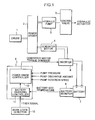
- FIG. 1 shows a hybrid working machine according to an embodiment of the invention.
- the hybrid working machine includes an engine 1, a power divider 2, a hydraulic pump 3, a generator motor 4, a plurality of hydraulic actuators, a plurality of control valves 5 provided for the respective actuators, a plurality of inverters 6, a battery 7, a controller 8, a battery monitor 9, and a working state detector 10.
- the engine 1 is connected in parallel to the hydraulic pump 3 and to the generator motor 4 via the power divider 2 to drive the hydraulic pump 3 and the generator motor 4.
- the hydraulic pump supplies hydraulic fluid to the hydraulic actuators via the respective control valves 5 to thereby drive the hydraulic actuators.
- the hydraulic actuators are, for example, a boom cylinder, an arm cylinder, a bucket cylinder, a propelling hydraulic motor, ant others.
- FIG. 1 exemplarily shows only one control valve 5 and one hydraulic actuator.
- FIG. 1 also shows only one hydraulic pump 3, but plural hydraulic pumps may be connected in series or in parallel to the hydraulic actuator.
- the generator motor 4 is connected to the battery 7 via the inverters 6.
- the battery 7 is, for example, a nickel-hydrogen battery or a lithium-ion battery.
- the generator motor 4 is operable to serve as a generator when being driven by the engine 1, thus generating an electric power for charging the battery 7.
- the generator motor 4 is also operable to serve as a motor for assisting the engine 1 by an electric power supplied from the battery 7.
- the battery monitor 9 generates a detection signal relating to SOC and temperature of the battery 7, and inputs the detection signal to the controller 8.
- the working state detector 10 detects information for discriminating between a working period during which the hydraulic actuator is driven and a standby period during which the hydraulic actuator is not driven, in other words, information relating to a working state.
- the working state detector 10, in this embodiment, outputs an operation detection signal (also called as a lever signal in the case of a remote control valve because the remote control valve has a lever and the lever is operated) indicative of presence or absence of an operation of an operating device (e.g. the above remote control valve) for actuating the control valve 5.
- the operation detection signal is also input to the controller 8.
- the hybrid working machine of this embodiment is further provided with not graphically expressed detectors for detecting a pump pressure, an ejection amount, and a rotating number of the hydraulic pump 3 respectively, based on which a power that the hydraulic actuator requires (actuator request power) is determined.
- the controller 8 is provided with a battery charging controller 11 for controlling charging of the battery 7 and a power share controller 12 for determining respective power shares of the generator motor 4 and the engine 1 in cooperation with the battery charging controller 11.
- the battery charging controller 11 stores a predetermined battery SOC/charging power map, reads a charging power corresponding to a detected battery SOC as a required charging power from the map, and transmits the read required charging power to the power share controller 12.
- the power share controller 12 determines the share of the engine power in the actuator request power, based on the required charging power transmitted from the power charging controller 11, and inputs a torque command to the generator motor 4 based on the determined engine power.
- the controller 8 further performs a battery charge control of rapid charging by full use of the battery performance determined by the detected battery temperature and SOC during a working period while limiting the charging power for standby period so as to protect the battery 7.
- the purpose of the control is as follows. During a working period, that is, during a period when the lever is operated, the working involves a battery discharge which sharply lowers the battery SOC, thereby causing a requirement of rapid charging to swiftly recover the battery SOC.
- the continuous rapid charging during a period when the machine is stopped may cause a trouble of excessive increase in the load of the battery 7, which shortens the battery life.
- FIG. 2 shows a battery SOC/charging power map for a working period (charging map for working period), and FIG. 3 shows a battery SOC/charging power map for a standby period (charging map for standby period).
- FIG. 2 also shows the charging map for standby period by the bold broken line for easy comparison between the above two maps.
- the charging map for working period is set for each of a plurality of different battery temperatures, for instance, six different battery temperatures of 0°C, 5°C, 10°C, 15°C, 20°C, and -5C°, from which the map corresponding to a detected battery temperature during the working period is read out.
- a detected temperature between two temperatures of the above set temperatures e.g. 3 °C or 18 °C
- the charging map for standby period be set for each of a plurality of different battery temperatures as well as the charging map for working period
- this embodiment includes, as shown in FIG. 3 , only one kind of map having no relation to a battery temperature for a standby period, for non-complicated control.
- a selection of a lower value, as a charging power for standby period, of two concurrently read charging powers specifically, a charging power based on the charging map for working period corresponding to the detected battery temperature and a charging power based on the charging map for standby period.
- the aforementioned map is set so that the charging power for standby period is lower than that during a working period, especially in an area used in a high frequency, that is, specifically, an area where the battery SOC is no less than 50%.
- the upper limit of the charging power is set higher than that during a standby period, in an area where the battery temperature is not a minus value, and the charging power is set higher than that during a standby period, in a full area of the battery SOC.
- the charging power for working period corresponding to the battery SOC of 70% is set to zero (in other words, a targeted value of the battery SOC is set to 70%)
- the charging power for standby period corresponding to the battery SOC of 65% is set to zero (in other words, a targeted value of the battery SOC is set to 65%).
- Step S1 the charging map for standby period is read out in Step S1, and the charging power for standby period PWb1 corresponding to the detected battery SOC is set.
- the charging map for working period is read in Step S2, and the working period charging power PWb2 corresponding to the detected battery temperature and the battery SOC is set.
- Step S3 a previous value of a required charging power to be used for the rate limiter process to be performed later is set to a value PWbrq0 which is one acquired at a time earlier by one control cycle.
- Step S4 is a judgment whether the lever is operated or not (whether it is a working period or a standby period).
- the charging power for working period PWb2 is set to a required charging power PWbrq, in Step S5.
- a lower value of the charging power for standby period Pub and the working period charging power PWb2 is set to the required charging power PWbrq, in Step S6.
- the charging power for working period PWb2 is set to the required charging power PWbrq, because the charging power for working period PWb2, in that area, is lower than the charging power for standby period PWb1, as shown in FIG. 2 .
- Step S7 performed is a rate limiter process for setting an amount of the change in the charging power lower than a value determined based on the map, upon switching between the charging map for working period and the charging map for standby period.
- Step S7 is a comparison between the required charging power PWbrq (set value) set in Step S5 or S6 and a value obtained by adding a predetermined value APWbrq (that is, a comparison value at the time of an increase in the charging power) to the previous value PWbrq0 acquired at a time earlier by one control cycle.
- a predetermined value APWbrq that is, a comparison value at the time of an increase in the charging power
- Step S8 In the case of YES in Step S7, that is, PWbrq>PWbrqO+OPWbrq, performed is Step S8, where the lower value (PWbrq0+ ⁇ PWbrq) is set as the required charging power (determined value).
- Step S9 which is a comparison between the set value PWbrq and a comparison value at the time of a decrease in the charging power, that is, a value obtained by subtracting the predetermined value APWbrq from the previous value PWbrq0.
- Step 510 where the higher value (PWbrq0- ⁇ Pwbrq) is set as the required charging power (determined value).
- Step S9 that is, in the case of neither PWbrq ⁇ PWbrq0+ ⁇ PWbrq nor PWbrq ⁇ PWbrq0- ⁇ PWbrq, the set value is set as the required charging power (determined value).
- Step S8 Step S10, and Step S9 (in the case of YES) is followed by Step S11, where the power share between the engine 1 and for the battery 7 is determined undert the limitation that the whole power does not exceed the required charging power PWbrq as a determined value, and, in accordance with the power share, a torque command is input to the generator motor 4.
- Step S11 is followed by returning to Step S1.
- This control enables the battery SOC, during a working period involving repeating discharge, to be swiftly recovered by rapid charging with full use of the battery performance, while protecting the battery, during a standby period involving no discharge, against the damage due to continuous rapid charging, by the charging power limitation heavier than that in a working period.
- the control makes it possible to perform a battery charge suitable both for a working period and for a standby period, thus extending the battery life while optimally keeping the battery SOC.
- Step S6 in FIG. 4 which is a selection of a lower value of the charging power PWb1 based on the charging map for working period corresponding to a detected battery temperature and the charging power PWb2 based on the charging map for standby period as the required charging power PWbrq during the standby period, makes it possible to drop the charging power for standby period in a low-temperature condition for protecting the battery 7, with a simplified control using only one kind of the stand-by period charging map having no relation to a battery temperature.
- the rate limiter process of Step S7 to Step S11 in FIG. 4 which suppresses a change amount of the charging power, makes the change in the charging power smooth, thereby protecting the battery 7.
- the invention is not limited to the embodiment, but may include the following modifications, for instance.
- the invention provides a hybrid working machine capable of performing battery charge control suitable for a working period and a standby period.
- the hybrid working machine comprises: a hydraulic actuator; an engine; a hydraulic pump which is connected to the engine and driven by an output power of the engine to supply hydraulic fluid to the hydraulic actuator; a battery; a generator motor which is connected to the engine to serve as a generator by the output power of the engine to charge the battery and as a motor for assisting the engine by supply of an electric power from the battery; a battery monitor which detects a battery SOC indicating a charging state of the battery; a controller which controls a charging power of the battery depending on the battery SOC detected by the battery monitor; and a working state detector which detects a working state as information for discriminating between a working period during which the hydraulic actuator is actuated and a standby period during which the hydraulic actuator is not actuated, wherein the controller limits the charging power in the standby period in comparison with in the working period.
- the working state detector provides information for discriminating between the working period and the standby period, and the controller limits the charging power in the standby period in comparison with in the working period; this enables both of swift recovery of the battery SOC by rapid charging with full use of the battery performance during the working period involving repeating discharging and protecting the battery against the damage due to continuous rapid charging during the standby period involving no discharge to be performed.
- the battery charge both for a working period and for a standby period can be performed, which results in both of optimally keeping the battery SOC and an improvement of the battery life while.
- the controller may determine a required charging power based on a predetermined charging map for working period as to a relation between battery SOC and a charging power during the working period and determine a required charging power based on a predetermined charging map for standby period according to battery SOC/charging power characteristics different from the charging map for working period so as to limit the charging power in the standby period in comparison with in the working period. More preferably, an upper limit of the charging power in the charging map for standby period may be set lower than that in the charging map for working period.
- the monitor detects a battery temperature
- the controller stores a plurality of maps corresponding to respective predetermined different battery temperatures as the charging map for working period and a single kind of a map having no relation to a battery temperature as the charging map for standby period
- the controller selects, during the standby period, a lower value of the charging power based on the charging map for working period corresponding to the detected battery temperature and the charging power based on the charging map for standby period, as the required charging power.
- the controller may, more preferably, perform a rate limiter process of setting a change amount of the charging power to a value lower than a value determined based on both of the charging map for working period and the charging map for standby period, upon switching between the charging map for working period and the charging map for standby period.
- the rate limiter process suppresses a change amount of the charging power upon switching the charging power between the working period and the standby period to make a change in the charging power smooth, thereby protecting the battery.
- the working state detector may be one which detects, as the working state, presence or absence of an operation of an operating device to be operated for actuating the hydraulic actuator.
- the hybrid working machine includes a hydraulic actuator, an engine, a hydraulic pump driven by the engine to supply hydraulic fluid to the hydraulic actuator, a battery, a generator motor connected to the engine to serve as a generator by an output power of the engine to charge the battery and serve as a motor for assisting the engine by supply of an electric power from the battery, a battery monitor detecting a battery SOC, a controller which controls a charging power of the battery depending on the battery SOC, and a working state detector detecting a working state as information for discriminating between a working period during which the hydraulic actuator is actuated and a standby period luring which the hydraulic actuator is not actuated.
- the controller limits the charging power in the standby period in comparison with in the working period.
Landscapes
- Engineering & Computer Science (AREA)
- Transportation (AREA)
- Mechanical Engineering (AREA)
- Automation & Control Theory (AREA)
- Chemical & Material Sciences (AREA)
- Combustion & Propulsion (AREA)
- General Engineering & Computer Science (AREA)
- Civil Engineering (AREA)
- Mining & Mineral Resources (AREA)
- Structural Engineering (AREA)
- Power Engineering (AREA)
- Secondary Cells (AREA)
- Charge And Discharge Circuits For Batteries Or The Like (AREA)
- Control Of Eletrric Generators (AREA)
- Operation Control Of Excavators (AREA)
- Control Of Vehicle Engines Or Engines For Specific Uses (AREA)
- Hybrid Electric Vehicles (AREA)
- Electric Propulsion And Braking For Vehicles (AREA)
Applications Claiming Priority (1)
| Application Number | Priority Date | Filing Date | Title |
|---|---|---|---|
| JP2010093220A JP5703587B2 (ja) | 2010-04-14 | 2010-04-14 | ハイブリッド作業機械 |
Publications (3)
| Publication Number | Publication Date |
|---|---|
| EP2377710A2 true EP2377710A2 (fr) | 2011-10-19 |
| EP2377710A3 EP2377710A3 (fr) | 2014-01-08 |
| EP2377710B1 EP2377710B1 (fr) | 2016-03-30 |
Family
ID=44122065
Family Applications (1)
| Application Number | Title | Priority Date | Filing Date |
|---|---|---|---|
| EP11162251.0A Not-in-force EP2377710B1 (fr) | 2010-04-14 | 2011-04-13 | Machine de travail hybride dotée d'une fonction de protection de la batterie |
Country Status (4)
| Country | Link |
|---|---|
| US (1) | US8421415B2 (fr) |
| EP (1) | EP2377710B1 (fr) |
| JP (1) | JP5703587B2 (fr) |
| CN (1) | CN102219017B (fr) |
Cited By (4)
| Publication number | Priority date | Publication date | Assignee | Title |
|---|---|---|---|---|
| EP2703567A1 (fr) * | 2012-08-30 | 2014-03-05 | Kobelco Construction Machinery Co., Ltd. | Machine de construction hybride |
| EP2749701A3 (fr) * | 2012-12-28 | 2015-01-21 | Kobelco Construction Machinery Co., Ltd. | Machine de construction de type hybride |
| EP2712968A3 (fr) * | 2012-09-28 | 2017-10-18 | Kabushiki Kaisha Kobe Seiko Sho (Kobe Steel, Ltd.) | Machine de construction avec unité de commande pour charger et décharger un dispositif de stockage électrique |
| EP3207585B2 (fr) † | 2014-10-13 | 2021-11-03 | ThyssenKrupp Marine Systems GmbH | Procédé de fonctionnement d'un réseau électrique, notamment d'un réseau électrique d'engin nautique |
Families Citing this family (24)
| Publication number | Priority date | Publication date | Assignee | Title |
|---|---|---|---|---|
| EP2725151B1 (fr) * | 2011-06-27 | 2016-08-03 | Sumitomo Heavy Industries, Ltd. | Machine de terrassement hybride et procédé de commande associé |
| CN102437629B (zh) * | 2011-11-01 | 2013-07-24 | 电子科技大学 | 一种电池充电控制装置 |
| CN104024540B (zh) * | 2011-12-28 | 2016-08-24 | 斗山英维高株式会社 | 混合动力工程机械的紧急停止方法及制动器控制装置 |
| JP5970898B2 (ja) * | 2012-03-26 | 2016-08-17 | コベルコ建機株式会社 | 動力伝達装置及びこれを備えたハイブリッド建設機械 |
| KR101643023B1 (ko) * | 2012-04-10 | 2016-07-26 | 현대중공업 주식회사 | 굴삭기 전기 동력시스템 |
| WO2014021363A1 (fr) * | 2012-08-02 | 2014-02-06 | 日産自動車株式会社 | Système de gestion de charge destiné à un véhicule de transport sans pilote et procédé de gestion de charge |
| JP6019956B2 (ja) * | 2012-09-06 | 2016-11-02 | コベルコ建機株式会社 | ハイブリッド建設機械の動力制御装置 |
| US9190852B2 (en) * | 2012-09-21 | 2015-11-17 | Caterpillar Global Mining Llc | Systems and methods for stabilizing power rate of change within generator based applications |
| JP6127550B2 (ja) * | 2013-02-05 | 2017-05-17 | コベルコ建機株式会社 | 建設機械 |
| JP2014167219A (ja) * | 2013-02-28 | 2014-09-11 | Kayaba Ind Co Ltd | ハイブリッド建設機械、コントローラ及び不揮発性メモリの書込処理方法 |
| WO2014208568A1 (fr) | 2013-06-26 | 2014-12-31 | 日立建機株式会社 | Engin de chantier hybride |
| JP6232795B2 (ja) * | 2013-07-18 | 2017-11-22 | コベルコ建機株式会社 | ハイブリッド建設機械 |
| JP6318496B2 (ja) * | 2013-08-07 | 2018-05-09 | コベルコ建機株式会社 | ハイブリッド建設機械の旋回電動機速度制御装置 |
| JP6197527B2 (ja) * | 2013-09-24 | 2017-09-20 | コベルコ建機株式会社 | ハイブリッド建設機械 |
| CN104002804B (zh) * | 2014-05-20 | 2016-03-09 | 中国科学院深圳先进技术研究院 | 一种燃料电池混合动力汽车的能量控制方法 |
| JP2016098588A (ja) * | 2014-11-25 | 2016-05-30 | Kyb株式会社 | ハイブリッド建設機械の制御システム |
| JP6647963B2 (ja) * | 2016-05-18 | 2020-02-14 | 日立建機株式会社 | 建設機械 |
| JP6944426B2 (ja) * | 2018-09-05 | 2021-10-06 | 株式会社日立建機ティエラ | 電動式建設機械 |
| US11511642B2 (en) | 2019-04-05 | 2022-11-29 | Oshkosh Corporation | Electric concrete vehicle systems and methods |
| US10981024B1 (en) | 2019-10-11 | 2021-04-20 | Oshkosh Corporation | Hybrid fire fighting vehicle |
| CN113047371A (zh) * | 2021-04-06 | 2021-06-29 | 山推工程机械股份有限公司 | 一种纯电动装载机 |
| CN113147720B (zh) * | 2021-05-08 | 2022-08-26 | 湖南三一路面机械有限公司 | 混合动力设备、混合动力系统、混合动力系统的控制方法 |
| CN113525270A (zh) * | 2021-07-15 | 2021-10-22 | 三一专用汽车有限责任公司 | 一种工程机械的供电方法、装置、系统及工程机械 |
| JP7782203B2 (ja) * | 2021-10-27 | 2025-12-09 | コベルコ建機株式会社 | 実機管理装置、及び実機管理システム |
Citations (2)
| Publication number | Priority date | Publication date | Assignee | Title |
|---|---|---|---|---|
| JP2005237178A (ja) | 2004-02-23 | 2005-09-02 | Kobelco Contstruction Machinery Ltd | 作業機械の動力源装置 |
| JP2010093220A (ja) | 2008-10-13 | 2010-04-22 | Askey Computer Corp | 隔離カバーを備える回路板及びその組立方法 |
Family Cites Families (13)
| Publication number | Priority date | Publication date | Assignee | Title |
|---|---|---|---|---|
| JP3828678B2 (ja) * | 1999-06-25 | 2006-10-04 | 株式会社神戸製鋼所 | ハイブリッド建設機械の制御装置 |
| WO2001000934A1 (fr) * | 1999-06-25 | 2001-01-04 | Kobelco Construction Machinery Co., Ltd. | Machine de chantier hybride et son dispositif de commande |
| JP4193371B2 (ja) * | 2001-04-25 | 2008-12-10 | トヨタ自動車株式会社 | バッテリ容量制御装置 |
| JP3859982B2 (ja) * | 2001-04-27 | 2006-12-20 | 株式会社神戸製鋼所 | ハイブリッド建設機械の電力制御装置 |
| JP2003328397A (ja) * | 2002-05-08 | 2003-11-19 | Hitachi Constr Mach Co Ltd | ハイブリッド建設機械 |
| JP2004347040A (ja) * | 2003-05-22 | 2004-12-09 | Kobelco Contstruction Machinery Ltd | 作業機械の制御装置 |
| JP4524679B2 (ja) | 2006-03-15 | 2010-08-18 | コベルコ建機株式会社 | ハイブリッド建設機械 |
| KR100821776B1 (ko) * | 2006-06-09 | 2008-04-11 | 현대자동차주식회사 | 하이브리드 차량에 구비된 메인 배터리의 충방전량 제어방법 |
| JP5055948B2 (ja) | 2006-10-20 | 2012-10-24 | コベルコ建機株式会社 | ハイブリッド作業機械 |
| JP2008121659A (ja) | 2006-10-20 | 2008-05-29 | Kobelco Contstruction Machinery Ltd | ハイブリッド作業機械 |
| CN101246976B (zh) * | 2008-03-25 | 2010-04-21 | 东南大学 | 铅酸蓄电池充电方法及其充电器 |
| KR101169962B1 (ko) * | 2008-04-11 | 2012-08-06 | 스미토모 겐키 가부시키가이샤 | 작업기계 |
| JP4609567B2 (ja) | 2008-10-29 | 2011-01-12 | コベルコ建機株式会社 | ハイブリッド作業機械 |
-
2010
- 2010-04-14 JP JP2010093220A patent/JP5703587B2/ja not_active Expired - Fee Related
-
2011
- 2011-04-12 US US13/084,759 patent/US8421415B2/en not_active Expired - Fee Related
- 2011-04-13 EP EP11162251.0A patent/EP2377710B1/fr not_active Not-in-force
- 2011-04-14 CN CN201110096143.3A patent/CN102219017B/zh not_active Expired - Fee Related
Patent Citations (2)
| Publication number | Priority date | Publication date | Assignee | Title |
|---|---|---|---|---|
| JP2005237178A (ja) | 2004-02-23 | 2005-09-02 | Kobelco Contstruction Machinery Ltd | 作業機械の動力源装置 |
| JP2010093220A (ja) | 2008-10-13 | 2010-04-22 | Askey Computer Corp | 隔離カバーを備える回路板及びその組立方法 |
Cited By (6)
| Publication number | Priority date | Publication date | Assignee | Title |
|---|---|---|---|---|
| EP2703567A1 (fr) * | 2012-08-30 | 2014-03-05 | Kobelco Construction Machinery Co., Ltd. | Machine de construction hybride |
| US8880265B2 (en) | 2012-08-30 | 2014-11-04 | Kobelco Construction Machinery Co., Ltd. | Hybrid construction machine |
| EP2712968A3 (fr) * | 2012-09-28 | 2017-10-18 | Kabushiki Kaisha Kobe Seiko Sho (Kobe Steel, Ltd.) | Machine de construction avec unité de commande pour charger et décharger un dispositif de stockage électrique |
| EP2749701A3 (fr) * | 2012-12-28 | 2015-01-21 | Kobelco Construction Machinery Co., Ltd. | Machine de construction de type hybride |
| US9013051B2 (en) | 2012-12-28 | 2015-04-21 | Kobelco Construction Machinery Co., Ltd. | Hybrid type construction machine |
| EP3207585B2 (fr) † | 2014-10-13 | 2021-11-03 | ThyssenKrupp Marine Systems GmbH | Procédé de fonctionnement d'un réseau électrique, notamment d'un réseau électrique d'engin nautique |
Also Published As
| Publication number | Publication date |
|---|---|
| US8421415B2 (en) | 2013-04-16 |
| EP2377710A3 (fr) | 2014-01-08 |
| CN102219017B (zh) | 2015-09-09 |
| JP2011220068A (ja) | 2011-11-04 |
| US20110254513A1 (en) | 2011-10-20 |
| CN102219017A (zh) | 2011-10-19 |
| JP5703587B2 (ja) | 2015-04-22 |
| EP2377710B1 (fr) | 2016-03-30 |
Similar Documents
| Publication | Publication Date | Title |
|---|---|---|
| EP2377710B1 (fr) | Machine de travail hybride dotée d'une fonction de protection de la batterie | |
| EP2204504B1 (fr) | Machine de travail hybride | |
| JP5764310B2 (ja) | 動力伝達装置 | |
| US9077272B2 (en) | Slewing-type working machine | |
| EP3141442B1 (fr) | Engin de chantier hybride | |
| CN103370247B (zh) | 蓄电器的充放电控制装置及方法、混合动力作业机械 | |
| JP5226733B2 (ja) | ハイブリッド建設機械およびハイブリッド建設機械の蓄電器容量計測方法 | |
| EP1720244A1 (fr) | Dispositif d alimentation de puissance pour machine-outil | |
| KR101892594B1 (ko) | 쇼벨 | |
| EP2826920B1 (fr) | Machine de construction hybride | |
| CN103370518B (zh) | 动力源装置及具备该动力源装置的混合动力工程机械 | |
| JP6180249B2 (ja) | 電池容量推定装置及び電池容量推定方法 | |
| EP3128086B1 (fr) | Pelle | |
| JP6162969B2 (ja) | 作業機械 | |
| EP2712968B1 (fr) | Machine de construction avec unité de commande pour charger et décharger un dispositif de stockage électrique | |
| EP3342940B1 (fr) | Engin de chantier hybride | |
| WO2015195895A1 (fr) | Mécanisme de commande de rendement énergétique pour une machine de travail | |
| EP3249115A1 (fr) | Machine de construction hybride | |
| JP7105665B2 (ja) | 建設機械 | |
| EP2990542B1 (fr) | Machine de construction hybride |
Legal Events
| Date | Code | Title | Description |
|---|---|---|---|
| AK | Designated contracting states |
Kind code of ref document: A2 Designated state(s): AL AT BE BG CH CY CZ DE DK EE ES FI FR GB GR HR HU IE IS IT LI LT LU LV MC MK MT NL NO PL PT RO RS SE SI SK SM TR |
|
| AX | Request for extension of the european patent |
Extension state: BA ME |
|
| PUAI | Public reference made under article 153(3) epc to a published international application that has entered the european phase |
Free format text: ORIGINAL CODE: 0009012 |
|
| PUAL | Search report despatched |
Free format text: ORIGINAL CODE: 0009013 |
|
| AK | Designated contracting states |
Kind code of ref document: A3 Designated state(s): AL AT BE BG CH CY CZ DE DK EE ES FI FR GB GR HR HU IE IS IT LI LT LU LV MC MK MT NL NO PL PT RO RS SE SI SK SM TR |
|
| AX | Request for extension of the european patent |
Extension state: BA ME |
|
| RIC1 | Information provided on ipc code assigned before grant |
Ipc: B60K 6/48 20071001AFI20131205BHEP Ipc: B60W 10/30 20060101ALI20131205BHEP Ipc: B60W 30/18 20120101ALI20131205BHEP Ipc: B60W 10/26 20060101ALI20131205BHEP Ipc: B60W 20/00 20060101ALI20131205BHEP |
|
| 17P | Request for examination filed |
Effective date: 20140221 |
|
| RBV | Designated contracting states (corrected) |
Designated state(s): AL AT BE BG CH CY CZ DE DK EE ES FI FR GB GR HR HU IE IS IT LI LT LU LV MC MK MT NL NO PL PT RO RS SE SI SK SM TR |
|
| GRAP | Despatch of communication of intention to grant a patent |
Free format text: ORIGINAL CODE: EPIDOSNIGR1 |
|
| INTG | Intention to grant announced |
Effective date: 20151006 |
|
| GRAS | Grant fee paid |
Free format text: ORIGINAL CODE: EPIDOSNIGR3 |
|
| GRAA | (expected) grant |
Free format text: ORIGINAL CODE: 0009210 |
|
| AK | Designated contracting states |
Kind code of ref document: B1 Designated state(s): AL AT BE BG CH CY CZ DE DK EE ES FI FR GB GR HR HU IE IS IT LI LT LU LV MC MK MT NL NO PL PT RO RS SE SI SK SM TR |
|
| REG | Reference to a national code |
Ref country code: GB Ref legal event code: FG4D |
|
| REG | Reference to a national code |
Ref country code: CH Ref legal event code: EP |
|
| REG | Reference to a national code |
Ref country code: AT Ref legal event code: REF Ref document number: 784958 Country of ref document: AT Kind code of ref document: T Effective date: 20160415 |
|
| REG | Reference to a national code |
Ref country code: IE Ref legal event code: FG4D |
|
| REG | Reference to a national code |
Ref country code: DE Ref legal event code: R096 Ref document number: 602011024512 Country of ref document: DE |
|
| REG | Reference to a national code |
Ref country code: FR Ref legal event code: PLFP Year of fee payment: 6 |
|
| REG | Reference to a national code |
Ref country code: LT Ref legal event code: MG4D |
|
| PG25 | Lapsed in a contracting state [announced via postgrant information from national office to epo] |
Ref country code: GR Free format text: LAPSE BECAUSE OF FAILURE TO SUBMIT A TRANSLATION OF THE DESCRIPTION OR TO PAY THE FEE WITHIN THE PRESCRIBED TIME-LIMIT Effective date: 20160701 Ref country code: HR Free format text: LAPSE BECAUSE OF FAILURE TO SUBMIT A TRANSLATION OF THE DESCRIPTION OR TO PAY THE FEE WITHIN THE PRESCRIBED TIME-LIMIT Effective date: 20160330 Ref country code: FI Free format text: LAPSE BECAUSE OF FAILURE TO SUBMIT A TRANSLATION OF THE DESCRIPTION OR TO PAY THE FEE WITHIN THE PRESCRIBED TIME-LIMIT Effective date: 20160330 Ref country code: NO Free format text: LAPSE BECAUSE OF FAILURE TO SUBMIT A TRANSLATION OF THE DESCRIPTION OR TO PAY THE FEE WITHIN THE PRESCRIBED TIME-LIMIT Effective date: 20160630 |
|
| REG | Reference to a national code |
Ref country code: NL Ref legal event code: MP Effective date: 20160330 |
|
| REG | Reference to a national code |
Ref country code: AT Ref legal event code: MK05 Ref document number: 784958 Country of ref document: AT Kind code of ref document: T Effective date: 20160330 |
|
| PG25 | Lapsed in a contracting state [announced via postgrant information from national office to epo] |
Ref country code: SE Free format text: LAPSE BECAUSE OF FAILURE TO SUBMIT A TRANSLATION OF THE DESCRIPTION OR TO PAY THE FEE WITHIN THE PRESCRIBED TIME-LIMIT Effective date: 20160330 Ref country code: RS Free format text: LAPSE BECAUSE OF FAILURE TO SUBMIT A TRANSLATION OF THE DESCRIPTION OR TO PAY THE FEE WITHIN THE PRESCRIBED TIME-LIMIT Effective date: 20160330 Ref country code: LV Free format text: LAPSE BECAUSE OF FAILURE TO SUBMIT A TRANSLATION OF THE DESCRIPTION OR TO PAY THE FEE WITHIN THE PRESCRIBED TIME-LIMIT Effective date: 20160330 Ref country code: BE Free format text: LAPSE BECAUSE OF NON-PAYMENT OF DUE FEES Effective date: 20160430 Ref country code: LT Free format text: LAPSE BECAUSE OF FAILURE TO SUBMIT A TRANSLATION OF THE DESCRIPTION OR TO PAY THE FEE WITHIN THE PRESCRIBED TIME-LIMIT Effective date: 20160330 |
|
| PG25 | Lapsed in a contracting state [announced via postgrant information from national office to epo] |
Ref country code: NL Free format text: LAPSE BECAUSE OF FAILURE TO SUBMIT A TRANSLATION OF THE DESCRIPTION OR TO PAY THE FEE WITHIN THE PRESCRIBED TIME-LIMIT Effective date: 20160330 |
|
| PG25 | Lapsed in a contracting state [announced via postgrant information from national office to epo] |
Ref country code: EE Free format text: LAPSE BECAUSE OF FAILURE TO SUBMIT A TRANSLATION OF THE DESCRIPTION OR TO PAY THE FEE WITHIN THE PRESCRIBED TIME-LIMIT Effective date: 20160330 Ref country code: IS Free format text: LAPSE BECAUSE OF FAILURE TO SUBMIT A TRANSLATION OF THE DESCRIPTION OR TO PAY THE FEE WITHIN THE PRESCRIBED TIME-LIMIT Effective date: 20160730 Ref country code: PL Free format text: LAPSE BECAUSE OF FAILURE TO SUBMIT A TRANSLATION OF THE DESCRIPTION OR TO PAY THE FEE WITHIN THE PRESCRIBED TIME-LIMIT Effective date: 20160330 |
|
| PG25 | Lapsed in a contracting state [announced via postgrant information from national office to epo] |
Ref country code: AT Free format text: LAPSE BECAUSE OF FAILURE TO SUBMIT A TRANSLATION OF THE DESCRIPTION OR TO PAY THE FEE WITHIN THE PRESCRIBED TIME-LIMIT Effective date: 20160330 Ref country code: SM Free format text: LAPSE BECAUSE OF FAILURE TO SUBMIT A TRANSLATION OF THE DESCRIPTION OR TO PAY THE FEE WITHIN THE PRESCRIBED TIME-LIMIT Effective date: 20160330 Ref country code: CZ Free format text: LAPSE BECAUSE OF FAILURE TO SUBMIT A TRANSLATION OF THE DESCRIPTION OR TO PAY THE FEE WITHIN THE PRESCRIBED TIME-LIMIT Effective date: 20160330 Ref country code: PT Free format text: LAPSE BECAUSE OF FAILURE TO SUBMIT A TRANSLATION OF THE DESCRIPTION OR TO PAY THE FEE WITHIN THE PRESCRIBED TIME-LIMIT Effective date: 20160801 Ref country code: RO Free format text: LAPSE BECAUSE OF FAILURE TO SUBMIT A TRANSLATION OF THE DESCRIPTION OR TO PAY THE FEE WITHIN THE PRESCRIBED TIME-LIMIT Effective date: 20160330 Ref country code: SK Free format text: LAPSE BECAUSE OF FAILURE TO SUBMIT A TRANSLATION OF THE DESCRIPTION OR TO PAY THE FEE WITHIN THE PRESCRIBED TIME-LIMIT Effective date: 20160330 Ref country code: ES Free format text: LAPSE BECAUSE OF FAILURE TO SUBMIT A TRANSLATION OF THE DESCRIPTION OR TO PAY THE FEE WITHIN THE PRESCRIBED TIME-LIMIT Effective date: 20160330 |
|
| REG | Reference to a national code |
Ref country code: CH Ref legal event code: PL |
|
| PG25 | Lapsed in a contracting state [announced via postgrant information from national office to epo] |
Ref country code: BE Free format text: LAPSE BECAUSE OF FAILURE TO SUBMIT A TRANSLATION OF THE DESCRIPTION OR TO PAY THE FEE WITHIN THE PRESCRIBED TIME-LIMIT Effective date: 20160330 |
|
| REG | Reference to a national code |
Ref country code: DE Ref legal event code: R097 Ref document number: 602011024512 Country of ref document: DE |
|
| REG | Reference to a national code |
Ref country code: IE Ref legal event code: MM4A |
|
| PG25 | Lapsed in a contracting state [announced via postgrant information from national office to epo] |
Ref country code: LI Free format text: LAPSE BECAUSE OF NON-PAYMENT OF DUE FEES Effective date: 20160430 Ref country code: DK Free format text: LAPSE BECAUSE OF FAILURE TO SUBMIT A TRANSLATION OF THE DESCRIPTION OR TO PAY THE FEE WITHIN THE PRESCRIBED TIME-LIMIT Effective date: 20160330 Ref country code: CH Free format text: LAPSE BECAUSE OF NON-PAYMENT OF DUE FEES Effective date: 20160430 |
|
| PLBE | No opposition filed within time limit |
Free format text: ORIGINAL CODE: 0009261 |
|
| STAA | Information on the status of an ep patent application or granted ep patent |
Free format text: STATUS: NO OPPOSITION FILED WITHIN TIME LIMIT |
|
| 26N | No opposition filed |
Effective date: 20170103 |
|
| REG | Reference to a national code |
Ref country code: FR Ref legal event code: PLFP Year of fee payment: 7 |
|
| PG25 | Lapsed in a contracting state [announced via postgrant information from national office to epo] |
Ref country code: IE Free format text: LAPSE BECAUSE OF NON-PAYMENT OF DUE FEES Effective date: 20160413 Ref country code: SI Free format text: LAPSE BECAUSE OF FAILURE TO SUBMIT A TRANSLATION OF THE DESCRIPTION OR TO PAY THE FEE WITHIN THE PRESCRIBED TIME-LIMIT Effective date: 20160330 |
|
| REG | Reference to a national code |
Ref country code: FR Ref legal event code: PLFP Year of fee payment: 8 |
|
| PG25 | Lapsed in a contracting state [announced via postgrant information from national office to epo] |
Ref country code: HU Free format text: LAPSE BECAUSE OF FAILURE TO SUBMIT A TRANSLATION OF THE DESCRIPTION OR TO PAY THE FEE WITHIN THE PRESCRIBED TIME-LIMIT; INVALID AB INITIO Effective date: 20110413 Ref country code: CY Free format text: LAPSE BECAUSE OF FAILURE TO SUBMIT A TRANSLATION OF THE DESCRIPTION OR TO PAY THE FEE WITHIN THE PRESCRIBED TIME-LIMIT Effective date: 20160330 |
|
| PG25 | Lapsed in a contracting state [announced via postgrant information from national office to epo] |
Ref country code: MT Free format text: LAPSE BECAUSE OF NON-PAYMENT OF DUE FEES Effective date: 20160430 Ref country code: LU Free format text: LAPSE BECAUSE OF NON-PAYMENT OF DUE FEES Effective date: 20160413 Ref country code: MC Free format text: LAPSE BECAUSE OF FAILURE TO SUBMIT A TRANSLATION OF THE DESCRIPTION OR TO PAY THE FEE WITHIN THE PRESCRIBED TIME-LIMIT Effective date: 20160330 Ref country code: MK Free format text: LAPSE BECAUSE OF FAILURE TO SUBMIT A TRANSLATION OF THE DESCRIPTION OR TO PAY THE FEE WITHIN THE PRESCRIBED TIME-LIMIT Effective date: 20160330 Ref country code: TR Free format text: LAPSE BECAUSE OF FAILURE TO SUBMIT A TRANSLATION OF THE DESCRIPTION OR TO PAY THE FEE WITHIN THE PRESCRIBED TIME-LIMIT Effective date: 20160330 |
|
| PG25 | Lapsed in a contracting state [announced via postgrant information from national office to epo] |
Ref country code: BG Free format text: LAPSE BECAUSE OF FAILURE TO SUBMIT A TRANSLATION OF THE DESCRIPTION OR TO PAY THE FEE WITHIN THE PRESCRIBED TIME-LIMIT Effective date: 20160330 |
|
| PG25 | Lapsed in a contracting state [announced via postgrant information from national office to epo] |
Ref country code: AL Free format text: LAPSE BECAUSE OF FAILURE TO SUBMIT A TRANSLATION OF THE DESCRIPTION OR TO PAY THE FEE WITHIN THE PRESCRIBED TIME-LIMIT Effective date: 20160330 |
|
| RIC2 | Information provided on ipc code assigned after grant |
Ipc: B60W 10/30 20060101ALI20131205BHEP Ipc: B60W 10/26 20060101ALI20131205BHEP Ipc: B60K 6/48 20071001AFI20131205BHEP Ipc: B60W 30/18 20120101ALI20131205BHEP Ipc: B60W 20/00 20160101ALI20131205BHEP |
|
| PGFP | Annual fee paid to national office [announced via postgrant information from national office to epo] |
Ref country code: FR Payment date: 20230309 Year of fee payment: 13 |
|
| PGFP | Annual fee paid to national office [announced via postgrant information from national office to epo] |
Ref country code: IT Payment date: 20230310 Year of fee payment: 13 Ref country code: GB Payment date: 20230302 Year of fee payment: 13 |
|
| PGFP | Annual fee paid to national office [announced via postgrant information from national office to epo] |
Ref country code: DE Payment date: 20230228 Year of fee payment: 13 |
|
| REG | Reference to a national code |
Ref country code: DE Ref legal event code: R119 Ref document number: 602011024512 Country of ref document: DE |
|
| GBPC | Gb: european patent ceased through non-payment of renewal fee |
Effective date: 20240413 |
|
| PG25 | Lapsed in a contracting state [announced via postgrant information from national office to epo] |
Ref country code: DE Free format text: LAPSE BECAUSE OF NON-PAYMENT OF DUE FEES Effective date: 20241105 |
|
| PG25 | Lapsed in a contracting state [announced via postgrant information from national office to epo] |
Ref country code: GB Free format text: LAPSE BECAUSE OF NON-PAYMENT OF DUE FEES Effective date: 20240413 |
|
| PG25 | Lapsed in a contracting state [announced via postgrant information from national office to epo] |
Ref country code: FR Free format text: LAPSE BECAUSE OF NON-PAYMENT OF DUE FEES Effective date: 20240430 |
|
| PG25 | Lapsed in a contracting state [announced via postgrant information from national office to epo] |
Ref country code: GB Free format text: LAPSE BECAUSE OF NON-PAYMENT OF DUE FEES Effective date: 20240413 Ref country code: FR Free format text: LAPSE BECAUSE OF NON-PAYMENT OF DUE FEES Effective date: 20240430 Ref country code: DE Free format text: LAPSE BECAUSE OF NON-PAYMENT OF DUE FEES Effective date: 20241105 |
|
| PG25 | Lapsed in a contracting state [announced via postgrant information from national office to epo] |
Ref country code: IT Free format text: LAPSE BECAUSE OF NON-PAYMENT OF DUE FEES Effective date: 20240413 |