EP2378006B1 - Dispositif de changement rapide doté d'un support de serrage actif pour l'accouplement d'un outil sur une machine de travail - Google Patents
Dispositif de changement rapide doté d'un support de serrage actif pour l'accouplement d'un outil sur une machine de travail Download PDFInfo
- Publication number
- EP2378006B1 EP2378006B1 EP11161157.0A EP11161157A EP2378006B1 EP 2378006 B1 EP2378006 B1 EP 2378006B1 EP 11161157 A EP11161157 A EP 11161157A EP 2378006 B1 EP2378006 B1 EP 2378006B1
- Authority
- EP
- European Patent Office
- Prior art keywords
- quick
- coupling
- hydraulic
- adapter
- change device
- Prior art date
- Legal status (The legal status is an assumption and is not a legal conclusion. Google has not performed a legal analysis and makes no representation as to the accuracy of the status listed.)
- Active
Links
Images


Classifications
-
- E—FIXED CONSTRUCTIONS
- E02—HYDRAULIC ENGINEERING; FOUNDATIONS; SOIL SHIFTING
- E02F—DREDGING; SOIL-SHIFTING
- E02F3/00—Dredgers; Soil-shifting machines
- E02F3/04—Dredgers; Soil-shifting machines mechanically-driven
- E02F3/28—Dredgers; Soil-shifting machines mechanically-driven with digging tools mounted on a dipper- or bucket-arm, i.e. there is either one arm or a pair of arms, e.g. dippers, buckets
- E02F3/36—Component parts
- E02F3/3604—Devices to connect tools to arms, booms or the like
- E02F3/3609—Devices to connect tools to arms, booms or the like of the quick acting type, e.g. controlled from the operator seat
- E02F3/3663—Devices to connect tools to arms, booms or the like of the quick acting type, e.g. controlled from the operator seat hydraulically-operated
-
- E—FIXED CONSTRUCTIONS
- E02—HYDRAULIC ENGINEERING; FOUNDATIONS; SOIL SHIFTING
- E02F—DREDGING; SOIL-SHIFTING
- E02F3/00—Dredgers; Soil-shifting machines
- E02F3/04—Dredgers; Soil-shifting machines mechanically-driven
- E02F3/28—Dredgers; Soil-shifting machines mechanically-driven with digging tools mounted on a dipper- or bucket-arm, i.e. there is either one arm or a pair of arms, e.g. dippers, buckets
- E02F3/36—Component parts
- E02F3/3604—Devices to connect tools to arms, booms or the like
- E02F3/3609—Devices to connect tools to arms, booms or the like of the quick acting type, e.g. controlled from the operator seat
- E02F3/3654—Devices to connect tools to arms, booms or the like of the quick acting type, e.g. controlled from the operator seat with energy coupler, e.g. coupler for hydraulic or electric lines, to provide energy to drive(s) mounted on the tool
Definitions
- the invention relates to a quick-change device for coupling a tool to a working machine according to the type specified in the preamble of claim 1.
- Such quick-change devices are for earthmoving machines, such.
- excavator to allow a simple and quick change between various hydraulic tools, such as sifting spoons, pans, hydraulic hammer or the like, well known.
- a generic quick-change device is in the WO 91/01414 disclosed.
- the disclosed quick-change device has a swivel and locking device comprehensive, associated with the excavator quick coupler and an adapter associated with the tool.
- the quick-change device also has an automatic, a quick coupler side and a adapterseiti-. ges clutch part comprehensive, hydraulic coupling, which automatically couples a backhoe-side hydraulic circuit with a tool-side hydraulic circuit when pivoting the two coupling parts together. Further actions on the part of the machine operator, namely leaving the cab of the excavator and manual production of the hydraulic coupling between the excavator side and the tool side hydraulic circuit are not required.
- Another generic quick-change device is in the DE 101 59 417 A1 described. This quick-change device is characterized inter alia by the fact that the quick coupler side and / or the adapter-side coupling block are movably mounted.
- the invention has for its object to provide a quick-change device for coupling a tool on a working machine according to that in the preamble of claim 1 such that a reliable working clutch is guaranteed.
- the quick-change device comprises a fixed to a machine quick coupler and a tool attached to an adapter and an effective between quick change and adapter locking device for producing a mechanical coupling between the machine and tool.
- the quick-change device also comprises a hydraulic clutch.
- the hydraulic clutch in turn comprises a quick coupler side hydraulic block with hydraulic lines and corresponding hydraulic coupling valves and an adapter-side coupling block with hydraulic lines and coupling valves.
- the quick coupler-side coupling block and / or the adapter-side coupling block is elastically mounted in its surrounding housing, that is, in the quick coupler-side housing or the adapter-side housing.
- the quick coupler-side coupling block in at least one of its hydraulic lines arranged downstream of the clutch valve, partially extending into the hydraulic line and slidably mounted in the hydraulic line in the flow direction S, designed as a hollow body Tensioning support on.
- the Verspann 100 in this case has on its located in the hydraulic line area a pressure application surface and stands with her out of the hydraulic line range over a molded-in area in this area abutment with the surrounding housing.
- the bracing support Due to the hydraulic fluid flowing through the coupling valves in the coupled state and the pressure application surface present on the bracing support, the bracing support according to the invention acts like a hydraulic cylinder and is traversed in the direction of flow S and braces against the surrounding housing with the contact surface. Due to the flexible mounting of the quick coupler side and / or the adapter side coupling block, the two coupling blocks are pressed against one another in response, so that the risk of leakage is significantly reduced.
- Verspanntic Another advantage of the Verspanntic invention is that this is due to the located in the hydraulic line, the pressure application area having region in the coupled state "automatically”, namely at flow of hydraulic fluid, is effective.
- the Verspann M on its located in the hydraulic line area on a pressure application surface.
- the ring-shaped end face - ring surface - the Verspann suction forms the pressure application surface.
- the Verspann is outside the hydraulic line to a flange-like approach with a housing aligned contact surface. Due to the conditional by the flange-like approach diameter enlargement of Verspann man is advantageously ensured that a "rich" stop between the Verspann silica. In addition, due to this training a "slipping" of Verspann man is not possible, i. a loss-proof positioning of the bracing support is also ensured.
- a seal preferably an O-ring seal, is arranged between the hydraulic line and the bracing support.
- the clutch valves are active clutch valves.
- Active Clutch Valves means that the clutch valves do not necessarily open when connecting the clutch blocks, but are actively opened or closed by energizing them.
- the usage of active coupling valves proves to be advantageous because they ensure a high flow with low space requirements.
- the coupling valves are designed as Kurzhubventile, where a stroke of, for example, 1 to 5 millimeters sufficient to actuate the valve. This proves to be advantageous because of the low valve lifts a compact design can be realized.
- the quick coupler-side and / or adapter-side coupling block is elastically mounted on its surrounding housing by means of an elastic pressing-off element.
- an elastic push-off element proves to be particularly advantageous since this represents a cost-effective and low-maintenance storage, which also also assumes a sealing function.
- Fig. 1 shows a quick-change device 10 via a sifting bucket 12 is releasably attached to an excavator 14. For reasons of clarity, only the boom of the excavator 14 is shown here.
- the quick-change device 10 comprises a connected to the boom quick coupler 16 and arranged on the spreader 12 adapter 18. About a - not shown and described locking device - is in a known manner, a mechanical coupling between quick coupler 16 and adapter 18 produced so that a simple and quick tool change, for example, a drop of the sieve spoon 12 shown and a recording of a hydraulic hammer or the like, is possible.
- the quick-change device 10 For connecting the tool, for example, the illustrated sieve spoon 12, to the hydraulic system of the excavator, the quick-change device 10 also has a generally designated by the reference numeral 20 hydraulic coupling.
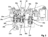
- the hydraulic coupling 20 in turn comprises a quick coupler-side coupling block 20a and an adapter-side coupling block 20b.
- the quick coupler side coupling block 20a hydraulic lines 22a, 24a and 26a and associated coupling valves 28a, 30a and 32a.
- the adapter-side coupling block 20b also has hydraulic lines 22b, 24b and 26b with associated coupling valves 28b, 30b 32b.
- the clutch valves 28a, 28b; 30a, 30b; 32a, 32b arranged in alignment with one another so that a flow of hydraulic fluid through the hydraulic lines 22a, 22b; 24a, 24b, and 26a, 26b guaranteed by the quick coupler 16 to the adapter 18 and vice versa.
- the Verspann 40 invention is most evident Fig. 3 seen. How out Fig. 3 can be seen, the coupling valve 30a in the flow direction S considered a Verspann pedal 34 downstream. Trained as a hollow body Verspann 400 34 extends partially in the hydraulic line 24a and is slidably viewed in the flow direction S in the hydraulic line 24a stored. In order to avoid an unwanted escape of hydraulic fluid between the outer peripheral surface of Verspann man 34 and the inner peripheral surface of the hydraulic line, the Verspann bicycle in its outer peripheral surface on a groove in which a corresponding seal 36 is introduced.
- the Verspann 150 at its end facing the coupling valve on a ring-shaped pressure application surface 38.
- the Verspann 150 has a flange-like projection 40.
- the flange-like projection 40 forms a contact surface 42, over which the Verspann man 34 is in contact with the surrounding housing 44,
- the effective piston area, on which the pressure prevailing in the valve acts is not limited to the pressure application surface 38, but as total surface of the diameter of the hydraulic line in which the Verspann silica 34 is guided and on the seal 36 seals. Ultimately, this is the effective area with which the two valve blocks are pressed against each other.
Landscapes
- Engineering & Computer Science (AREA)
- Mechanical Engineering (AREA)
- Mining & Mineral Resources (AREA)
- Civil Engineering (AREA)
- General Engineering & Computer Science (AREA)
- Structural Engineering (AREA)
- Quick-Acting Or Multi-Walled Pipe Joints (AREA)
- Acyclic And Carbocyclic Compounds In Medicinal Compositions (AREA)
- Fluid-Pressure Circuits (AREA)
Claims (7)
- Dispositif d'attache rapide (10) servant à accoupler un outil (12) à une machine de travail (14), comprenant :- un système d'attache rapide (16) fixé à une machine de travail (14);- un adaptateur (18) fixé à l'outil (12);- un système de verrouillage agissant entre le système d'attache rapide (16) et l'adaptateur (18) pour obtenir un accouplement mécanique entre la machine de travail (14) et l'outil (12);- un accouplement hydraulique (20) destiné à obtenir une liaison hydraulique entre un système hydraulique présent sur la machine de travail (14) et un système hydraulique de l'outil (12), dans lequel l'accouplement hydraulique (20) comprend un bloc d'accouplement (20a) côté système d'attache rapide comportant des conduites hydrauliques (22a, 24a, 26a) et des soupapes d'accouplement (28a, 30a, 32a) -bloc d'accouplement côté système d'attache rapide- et un bloc d'accouplement (20b) côté adaptateur comprenant des conduites hydrauliques (22b, 24b, 26b) et des soupapes d'accouplement (28b, 30b, 32b) - bloc d'accouplement côté adaptateur-, et au moins un bloc d'accouplement (20a, 20b) est monté de manière élastique dans son logement (44) qui l'entoure,dans lequel le bloc d'accouplement (20a) côté système d'attache rapide comprend dans au moins une première conduite hydraulique (22a, 24a, 26a) de ses conduites hydrauliques (22a, 24a, 26a) dans la direction d'écoulement (S), vu du bloc d'accouplement (20b) côté adaptateur au bloc d'accouplement (20b) côté système d'attache rapide, un support de serrage (34) agencé côté aval des soupapes d'accouplement côté système d'attache rapide, pénétrant par endroits dans la première conduite hydraulique (22a, 24a, 26a), monté dans la première conduite hydraulique (22a, 24a, 26a) de manière à pouvoir se déplacer dans la direction d'écoulement (S) et réalisé sous la forme d'un corps creux, caractérisé en ce que le support de serrage (34) présente une surface frontale qui pénètre dans la première conduite hydraulique (22a, 24a, 26a) et qui forme une surface d'application de pression (38) et en ce que le support de serrage (34) présente sur sa zone faisant saillie de la première conduite hydraulique (22a, 24a, 26a) une surface de butée (42) par l'intermédiaire de laquelle le support de serrage (34) est en butée avec le logement (44) du système d'attache rapide (16) qui l'entoure.
- Dispositif d'attache rapide (10) selon la revendication 1, caractérisé en ce que la surface d'application de pression (38) est réalisée sous la forme d'une surface annulaire.
- Dispositif d'attache rapide (10) selon la revendication 1 ou 2, caractérisé en ce que le support de serrage (34) présente à l'extérieur de la première conduite hydraulique (22a, 24a, 26a) une partie saillante (40) réalisée sous forme de bride, sur laquelle la surface d'appui (42) est formée.
- Dispositif d'attache rapide (10) selon l'une quelconque des revendications précédentes, caractérisé en ce qu'un joint (36), en particulier un joint torique, est agencé entre la première conduite hydraulique (22a, 24a, 26a) et le support de serrage (34).
- Dispositif d'attache rapide (10) selon l'une quelconque des revendications précédentes, caractérisé en ce que les soupapes d'accouplement (28a, 30a, 32a; 28b, 30b, 32b) sont des soupapes d'accouplement actives,
- Dispositif d'attache rapide (10) selon l'une quelconque des revendications 1 à 4, caractérisé en ce que les soupapes d'accouplement (28a, 30a, 32a; 28b, 30b, 32b) sont des soupapes à course courte.
- Dispositif d'attache rapide (10) selon l'une quelconque des revendications précédentes, caractérisé en ce que le bloc d'accouplement (20a, 20b) côté système d'échange rapide flou côté adaptateur est monté de manière élastique sur son logement (44) qui l'entoure au moyen d'un élément presseur élastique.
Priority Applications (1)
| Application Number | Priority Date | Filing Date | Title |
|---|---|---|---|
| PL11161157T PL2378006T3 (pl) | 2010-04-16 | 2011-04-05 | Urządzenie do szybkiej wymiany z aktywną podporą mocującą do doczepiania narzędzia do maszyny roboczej |
Applications Claiming Priority (1)
| Application Number | Priority Date | Filing Date | Title |
|---|---|---|---|
| DE102010016491A DE102010016491B4 (de) | 2010-04-16 | 2010-04-16 | Schnellwechselvorrichtung zum Ankuppeln eines Werkzeugs an eine Arbeitsmaschine |
Publications (2)
| Publication Number | Publication Date |
|---|---|
| EP2378006A1 EP2378006A1 (fr) | 2011-10-19 |
| EP2378006B1 true EP2378006B1 (fr) | 2016-12-14 |
Family
ID=44117426
Family Applications (1)
| Application Number | Title | Priority Date | Filing Date |
|---|---|---|---|
| EP11161157.0A Active EP2378006B1 (fr) | 2010-04-16 | 2011-04-05 | Dispositif de changement rapide doté d'un support de serrage actif pour l'accouplement d'un outil sur une machine de travail |
Country Status (6)
| Country | Link |
|---|---|
| EP (1) | EP2378006B1 (fr) |
| DE (1) | DE102010016491B4 (fr) |
| DK (1) | DK2378006T3 (fr) |
| ES (1) | ES2616785T3 (fr) |
| HU (1) | HUE033323T2 (fr) |
| PL (1) | PL2378006T3 (fr) |
Families Citing this family (3)
| Publication number | Priority date | Publication date | Assignee | Title |
|---|---|---|---|---|
| EP3722513A1 (fr) * | 2019-04-09 | 2020-10-14 | R&R exca Oy | Système de couplage pour coupler des outils à un bras d'excavateur et utilisations du système de couplage |
| CN113653123B (zh) * | 2021-09-23 | 2022-08-23 | 扬州扬子到河复合材料制品有限公司 | 一种多功能挖掘机工具箱后罩及其加工工艺 |
| CN116815862B (zh) * | 2023-04-26 | 2023-12-08 | 徐州巴特工程机械股份有限公司 | 一种集双锁装置于抓钩系统的全自动快换 |
Family Cites Families (8)
| Publication number | Priority date | Publication date | Assignee | Title |
|---|---|---|---|---|
| SE463319B (sv) * | 1989-07-18 | 1990-11-05 | John Teodor Sonerud | Koppling av drivsystem till ett arbetsredskap paa en graevmaskin eller liknande |
| SE510095C2 (sv) * | 1996-02-23 | 1999-04-19 | Dart Engineering Ag | Anordning vid snabbkoppling |
| DE10159417C2 (de) * | 2001-03-09 | 2003-12-11 | Liebherr Hydraulikbagger | Schnellkupplung |
| FR2854415B1 (fr) * | 2003-04-30 | 2005-07-08 | Const Du Beaujolais Atel | Dispositif securise de verrouillage hydraulique d'attaches rapides et de connexions hydrauliques associees, entre le coupleur d'un bras porteur d'un engin et un outil |
| AT7773U1 (de) * | 2004-02-23 | 2005-08-25 | Wimmer Alois Ing | Anordnung zum verbinden von energieleitungen, insbesondere druckleitungen |
| DE102004014824B4 (de) * | 2004-03-24 | 2019-08-01 | Lehnhoff Hartstahl Gmbh | Schnellwechselvorrichtung mit einer hydraulischen Kupplung für die Medien an einem Baugerät |
| FR2886372B1 (fr) * | 2005-05-25 | 2009-02-06 | Const Du Beaujolais Sa Atel | Dispositif destine a realiser l'alimentation en huile d'un outil monte sur un engin porteur et ensemble de connexion hydraulique |
| EP2367984B1 (fr) * | 2008-11-27 | 2020-06-03 | Caterpillar Work Tools B.V. | Dispositif de couplage pour outil d'engin de terrassement |
-
2010
- 2010-04-16 DE DE102010016491A patent/DE102010016491B4/de active Active
-
2011
- 2011-04-05 PL PL11161157T patent/PL2378006T3/pl unknown
- 2011-04-05 DK DK11161157.0T patent/DK2378006T3/en active
- 2011-04-05 HU HUE11161157A patent/HUE033323T2/en unknown
- 2011-04-05 ES ES11161157.0T patent/ES2616785T3/es active Active
- 2011-04-05 EP EP11161157.0A patent/EP2378006B1/fr active Active
Non-Patent Citations (1)
| Title |
|---|
| None * |
Also Published As
| Publication number | Publication date |
|---|---|
| DE102010016491B4 (de) | 2012-09-27 |
| ES2616785T3 (es) | 2017-06-14 |
| DE102010016491A1 (de) | 2011-10-20 |
| HUE033323T2 (en) | 2017-11-28 |
| EP2378006A1 (fr) | 2011-10-19 |
| DK2378006T3 (en) | 2017-03-13 |
| PL2378006T3 (pl) | 2017-08-31 |
Similar Documents
| Publication | Publication Date | Title |
|---|---|---|
| EP0968382B1 (fr) | Soupape a double siege nettoyable | |
| DE112008001503T5 (de) | Hydrauliksystem mit einer externen Druckkompensationsvorrichtung | |
| DE102012001562A1 (de) | Ventilanordnung für eine mobile Arbeitsmaschine | |
| DE102010010061A1 (de) | Mehrwegeventil | |
| DE112006001100T5 (de) | Hydrauliksystem mit Druckkompensator | |
| EP1566490B1 (fr) | Arrangement pour raccorder des conduites d'énergie, notamment des conduites de pression | |
| DE112008000200T5 (de) | Schwingungsunterdrückungsvorrichtung für hydraulische Arbeitsmaschine und hydraulische Arbeitsmaschine | |
| WO2017125108A1 (fr) | Système de changement de vitesse hydraulique conçu pour un véhicule automobile | |
| DE202009007668U1 (de) | Lasthalteventil mit Druckbegrenzungsfunktion | |
| DE102013015481A1 (de) | Steuervorrichtung zum wahlweisen fluidischen Verbinden und Trennen von Fluid-Anschlussstellen | |
| DE102009026704A1 (de) | Schmiervorrichtung für ein Planetengetriebe | |
| DE102006039731B4 (de) | Kettenspanneinrichtung | |
| DE102010016491B4 (de) | Schnellwechselvorrichtung zum Ankuppeln eines Werkzeugs an eine Arbeitsmaschine | |
| EP3436705B1 (fr) | Dispositif de commande | |
| EP2354564B1 (fr) | Sécurité anti-rupture de tuyau pour engins de levage actionnés de manière hydraulique | |
| DE102006053897A1 (de) | Hydraulisches Zweikreissystem und Zusammenschaltventilanordnung | |
| DE112021005232T5 (de) | Kugelschwimmer-Entlüftungsventil | |
| DE102004015471A1 (de) | Schnellwechsler für Bagger | |
| DE102015116295A1 (de) | Neigezylinderanordnung eines Hubmastes einer mobilen Arbeitsmaschine | |
| DE102013019093A1 (de) | Formschlusskopplungsvorrichtung | |
| DE102013223754A1 (de) | Entlüftungseinrichtung für ein hydraulisches System | |
| DE102012101715B4 (de) | Kupplung zur Verbindung zweier Hydrauliksysteme | |
| EP1703185B1 (fr) | Soupape coaxiale | |
| EP2786009B1 (fr) | Accouplement pour raccorder deux conduites guidant des fluides ainsi que dispositif d'entraînement | |
| DE102009043568A1 (de) | Sicherheitsventil |
Legal Events
| Date | Code | Title | Description |
|---|---|---|---|
| AK | Designated contracting states |
Kind code of ref document: A1 Designated state(s): AL AT BE BG CH CY CZ DE DK EE ES FI FR GB GR HR HU IE IS IT LI LT LU LV MC MK MT NL NO PL PT RO RS SE SI SK SM TR |
|
| AX | Request for extension of the european patent |
Extension state: BA ME |
|
| PUAI | Public reference made under article 153(3) epc to a published international application that has entered the european phase |
Free format text: ORIGINAL CODE: 0009012 |
|
| 17P | Request for examination filed |
Effective date: 20120417 |
|
| GRAP | Despatch of communication of intention to grant a patent |
Free format text: ORIGINAL CODE: EPIDOSNIGR1 |
|
| INTG | Intention to grant announced |
Effective date: 20160711 |
|
| GRAS | Grant fee paid |
Free format text: ORIGINAL CODE: EPIDOSNIGR3 |
|
| STAA | Information on the status of an ep patent application or granted ep patent |
Free format text: STATUS: GRANT OF PATENT IS INTENDED |
|
| GRAA | (expected) grant |
Free format text: ORIGINAL CODE: 0009210 |
|
| STAA | Information on the status of an ep patent application or granted ep patent |
Free format text: STATUS: THE PATENT HAS BEEN GRANTED |
|
| AK | Designated contracting states |
Kind code of ref document: B1 Designated state(s): AL AT BE BG CH CY CZ DE DK EE ES FI FR GB GR HR HU IE IS IT LI LT LU LV MC MK MT NL NO PL PT RO RS SE SI SK SM TR |
|
| REG | Reference to a national code |
Ref country code: GB Ref legal event code: FG4D Free format text: NOT ENGLISH |
|
| REG | Reference to a national code |
Ref country code: CH Ref legal event code: EP |
|
| REG | Reference to a national code |
Ref country code: CH Ref legal event code: NV Representative=s name: AMMANN PATENTANWAELTE AG BERN, CH |
|
| REG | Reference to a national code |
Ref country code: IE Ref legal event code: FG4D Free format text: LANGUAGE OF EP DOCUMENT: GERMAN |
|
| REG | Reference to a national code |
Ref country code: AT Ref legal event code: REF Ref document number: 853713 Country of ref document: AT Kind code of ref document: T Effective date: 20170115 |
|
| REG | Reference to a national code |
Ref country code: DE Ref legal event code: R096 Ref document number: 502011011312 Country of ref document: DE |
|
| PG25 | Lapsed in a contracting state [announced via postgrant information from national office to epo] |
Ref country code: LV Free format text: LAPSE BECAUSE OF FAILURE TO SUBMIT A TRANSLATION OF THE DESCRIPTION OR TO PAY THE FEE WITHIN THE PRESCRIBED TIME-LIMIT Effective date: 20161214 |
|
| REG | Reference to a national code |
Ref country code: NL Ref legal event code: FP |
|
| REG | Reference to a national code |
Ref country code: DK Ref legal event code: T3 Effective date: 20170310 |
|
| REG | Reference to a national code |
Ref country code: SE Ref legal event code: TRGR |
|
| REG | Reference to a national code |
Ref country code: LT Ref legal event code: MG4D |
|
| REG | Reference to a national code |
Ref country code: FR Ref legal event code: PLFP Year of fee payment: 7 |
|
| PG25 | Lapsed in a contracting state [announced via postgrant information from national office to epo] |
Ref country code: LT Free format text: LAPSE BECAUSE OF FAILURE TO SUBMIT A TRANSLATION OF THE DESCRIPTION OR TO PAY THE FEE WITHIN THE PRESCRIBED TIME-LIMIT Effective date: 20161214 Ref country code: GR Free format text: LAPSE BECAUSE OF FAILURE TO SUBMIT A TRANSLATION OF THE DESCRIPTION OR TO PAY THE FEE WITHIN THE PRESCRIBED TIME-LIMIT Effective date: 20170315 |
|
| REG | Reference to a national code |
Ref country code: NO Ref legal event code: T2 Effective date: 20161214 |
|
| PG25 | Lapsed in a contracting state [announced via postgrant information from national office to epo] |
Ref country code: HR Free format text: LAPSE BECAUSE OF FAILURE TO SUBMIT A TRANSLATION OF THE DESCRIPTION OR TO PAY THE FEE WITHIN THE PRESCRIBED TIME-LIMIT Effective date: 20161214 Ref country code: RS Free format text: LAPSE BECAUSE OF FAILURE TO SUBMIT A TRANSLATION OF THE DESCRIPTION OR TO PAY THE FEE WITHIN THE PRESCRIBED TIME-LIMIT Effective date: 20161214 Ref country code: FI Free format text: LAPSE BECAUSE OF FAILURE TO SUBMIT A TRANSLATION OF THE DESCRIPTION OR TO PAY THE FEE WITHIN THE PRESCRIBED TIME-LIMIT Effective date: 20161214 |
|
| REG | Reference to a national code |
Ref country code: ES Ref legal event code: FG2A Ref document number: 2616785 Country of ref document: ES Kind code of ref document: T3 Effective date: 20170614 |
|
| PG25 | Lapsed in a contracting state [announced via postgrant information from national office to epo] |
Ref country code: RO Free format text: LAPSE BECAUSE OF FAILURE TO SUBMIT A TRANSLATION OF THE DESCRIPTION OR TO PAY THE FEE WITHIN THE PRESCRIBED TIME-LIMIT Effective date: 20161214 Ref country code: IS Free format text: LAPSE BECAUSE OF FAILURE TO SUBMIT A TRANSLATION OF THE DESCRIPTION OR TO PAY THE FEE WITHIN THE PRESCRIBED TIME-LIMIT Effective date: 20170414 Ref country code: EE Free format text: LAPSE BECAUSE OF FAILURE TO SUBMIT A TRANSLATION OF THE DESCRIPTION OR TO PAY THE FEE WITHIN THE PRESCRIBED TIME-LIMIT Effective date: 20161214 Ref country code: SK Free format text: LAPSE BECAUSE OF FAILURE TO SUBMIT A TRANSLATION OF THE DESCRIPTION OR TO PAY THE FEE WITHIN THE PRESCRIBED TIME-LIMIT Effective date: 20161214 |
|
| PG25 | Lapsed in a contracting state [announced via postgrant information from national office to epo] |
Ref country code: SM Free format text: LAPSE BECAUSE OF FAILURE TO SUBMIT A TRANSLATION OF THE DESCRIPTION OR TO PAY THE FEE WITHIN THE PRESCRIBED TIME-LIMIT Effective date: 20161214 Ref country code: PT Free format text: LAPSE BECAUSE OF FAILURE TO SUBMIT A TRANSLATION OF THE DESCRIPTION OR TO PAY THE FEE WITHIN THE PRESCRIBED TIME-LIMIT Effective date: 20170414 Ref country code: BG Free format text: LAPSE BECAUSE OF FAILURE TO SUBMIT A TRANSLATION OF THE DESCRIPTION OR TO PAY THE FEE WITHIN THE PRESCRIBED TIME-LIMIT Effective date: 20170314 |
|
| REG | Reference to a national code |
Ref country code: DE Ref legal event code: R097 Ref document number: 502011011312 Country of ref document: DE |
|
| PLBE | No opposition filed within time limit |
Free format text: ORIGINAL CODE: 0009261 |
|
| STAA | Information on the status of an ep patent application or granted ep patent |
Free format text: STATUS: NO OPPOSITION FILED WITHIN TIME LIMIT |
|
| 26N | No opposition filed |
Effective date: 20170915 |
|
| REG | Reference to a national code |
Ref country code: HU Ref legal event code: AG4A Ref document number: E033323 Country of ref document: HU |
|
| REG | Reference to a national code |
Ref country code: DE Ref legal event code: R082 Ref document number: 502011011312 Country of ref document: DE Representative=s name: PUSCHMANN BORCHERT KAISER KLETTNER PATENTANWAE, DE Ref country code: DE Ref legal event code: R082 Ref document number: 502011011312 Country of ref document: DE Representative=s name: PUSCHMANN BORCHERT BARDEHLE PATENTANWAELTE PAR, DE Ref country code: DE Ref legal event code: R081 Ref document number: 502011011312 Country of ref document: DE Owner name: LEHNHOFF HARTSTAHL GMBH, DE Free format text: FORMER OWNER: LEHNHOFF HARTSTAHL GMBH & CO. KG, 76534 BADEN-BADEN, DE |
|
| REG | Reference to a national code |
Ref country code: IE Ref legal event code: MM4A |
|
| PG25 | Lapsed in a contracting state [announced via postgrant information from national office to epo] |
Ref country code: MC Free format text: LAPSE BECAUSE OF FAILURE TO SUBMIT A TRANSLATION OF THE DESCRIPTION OR TO PAY THE FEE WITHIN THE PRESCRIBED TIME-LIMIT Effective date: 20161214 |
|
| PG25 | Lapsed in a contracting state [announced via postgrant information from national office to epo] |
Ref country code: LU Free format text: LAPSE BECAUSE OF NON-PAYMENT OF DUE FEES Effective date: 20170405 Ref country code: SI Free format text: LAPSE BECAUSE OF FAILURE TO SUBMIT A TRANSLATION OF THE DESCRIPTION OR TO PAY THE FEE WITHIN THE PRESCRIBED TIME-LIMIT Effective date: 20161214 |
|
| REG | Reference to a national code |
Ref country code: FR Ref legal event code: PLFP Year of fee payment: 8 |
|
| PG25 | Lapsed in a contracting state [announced via postgrant information from national office to epo] |
Ref country code: IE Free format text: LAPSE BECAUSE OF NON-PAYMENT OF DUE FEES Effective date: 20170405 |
|
| PGFP | Annual fee paid to national office [announced via postgrant information from national office to epo] |
Ref country code: CZ Payment date: 20180323 Year of fee payment: 8 |
|
| PGFP | Annual fee paid to national office [announced via postgrant information from national office to epo] |
Ref country code: PL Payment date: 20180328 Year of fee payment: 8 Ref country code: TR Payment date: 20180328 Year of fee payment: 8 |
|
| REG | Reference to a national code |
Ref country code: AT Ref legal event code: MM01 Ref document number: 853713 Country of ref document: AT Kind code of ref document: T Effective date: 20170405 |
|
| PGFP | Annual fee paid to national office [announced via postgrant information from national office to epo] |
Ref country code: NO Payment date: 20180420 Year of fee payment: 8 Ref country code: DK Payment date: 20180424 Year of fee payment: 8 |
|
| PG25 | Lapsed in a contracting state [announced via postgrant information from national office to epo] |
Ref country code: AT Free format text: LAPSE BECAUSE OF NON-PAYMENT OF DUE FEES Effective date: 20170405 |
|
| PG25 | Lapsed in a contracting state [announced via postgrant information from national office to epo] |
Ref country code: MT Free format text: LAPSE BECAUSE OF FAILURE TO SUBMIT A TRANSLATION OF THE DESCRIPTION OR TO PAY THE FEE WITHIN THE PRESCRIBED TIME-LIMIT Effective date: 20161214 |
|
| PGFP | Annual fee paid to national office [announced via postgrant information from national office to epo] |
Ref country code: HU Payment date: 20180322 Year of fee payment: 8 Ref country code: SE Payment date: 20180424 Year of fee payment: 8 |
|
| PG25 | Lapsed in a contracting state [announced via postgrant information from national office to epo] |
Ref country code: CY Free format text: LAPSE BECAUSE OF NON-PAYMENT OF DUE FEES Effective date: 20161214 Ref country code: CZ Free format text: LAPSE BECAUSE OF NON-PAYMENT OF DUE FEES Effective date: 20190405 |
|
| REG | Reference to a national code |
Ref country code: NO Ref legal event code: MMEP |
|
| PG25 | Lapsed in a contracting state [announced via postgrant information from national office to epo] |
Ref country code: MK Free format text: LAPSE BECAUSE OF FAILURE TO SUBMIT A TRANSLATION OF THE DESCRIPTION OR TO PAY THE FEE WITHIN THE PRESCRIBED TIME-LIMIT Effective date: 20161214 |
|
| REG | Reference to a national code |
Ref country code: DK Ref legal event code: EBP Effective date: 20190430 |
|
| REG | Reference to a national code |
Ref country code: SE Ref legal event code: EUG |
|
| PG25 | Lapsed in a contracting state [announced via postgrant information from national office to epo] |
Ref country code: NO Free format text: LAPSE BECAUSE OF NON-PAYMENT OF DUE FEES Effective date: 20190430 Ref country code: SE Free format text: LAPSE BECAUSE OF NON-PAYMENT OF DUE FEES Effective date: 20190406 Ref country code: HU Free format text: LAPSE BECAUSE OF NON-PAYMENT OF DUE FEES Effective date: 20190406 |
|
| PG25 | Lapsed in a contracting state [announced via postgrant information from national office to epo] |
Ref country code: DK Free format text: LAPSE BECAUSE OF NON-PAYMENT OF DUE FEES Effective date: 20190430 |
|
| PG25 | Lapsed in a contracting state [announced via postgrant information from national office to epo] |
Ref country code: AL Free format text: LAPSE BECAUSE OF FAILURE TO SUBMIT A TRANSLATION OF THE DESCRIPTION OR TO PAY THE FEE WITHIN THE PRESCRIBED TIME-LIMIT Effective date: 20161214 |
|
| PG25 | Lapsed in a contracting state [announced via postgrant information from national office to epo] |
Ref country code: PL Free format text: LAPSE BECAUSE OF NON-PAYMENT OF DUE FEES Effective date: 20190405 |
|
| PG25 | Lapsed in a contracting state [announced via postgrant information from national office to epo] |
Ref country code: TR Free format text: LAPSE BECAUSE OF NON-PAYMENT OF DUE FEES Effective date: 20190405 |
|
| PGFP | Annual fee paid to national office [announced via postgrant information from national office to epo] |
Ref country code: IT Payment date: 20230428 Year of fee payment: 13 Ref country code: FR Payment date: 20230417 Year of fee payment: 13 |
|
| PG25 | Lapsed in a contracting state [announced via postgrant information from national office to epo] |
Ref country code: FR Free format text: LAPSE BECAUSE OF NON-PAYMENT OF DUE FEES Effective date: 20240430 |
|
| PG25 | Lapsed in a contracting state [announced via postgrant information from national office to epo] |
Ref country code: FR Free format text: LAPSE BECAUSE OF NON-PAYMENT OF DUE FEES Effective date: 20240430 |
|
| PG25 | Lapsed in a contracting state [announced via postgrant information from national office to epo] |
Ref country code: IT Free format text: LAPSE BECAUSE OF NON-PAYMENT OF DUE FEES Effective date: 20240405 |
|
| PGFP | Annual fee paid to national office [announced via postgrant information from national office to epo] |
Ref country code: NL Payment date: 20250423 Year of fee payment: 15 |
|
| PGFP | Annual fee paid to national office [announced via postgrant information from national office to epo] |
Ref country code: DE Payment date: 20250429 Year of fee payment: 15 |
|
| PGFP | Annual fee paid to national office [announced via postgrant information from national office to epo] |
Ref country code: GB Payment date: 20250417 Year of fee payment: 15 Ref country code: ES Payment date: 20250519 Year of fee payment: 15 |
|
| PGFP | Annual fee paid to national office [announced via postgrant information from national office to epo] |
Ref country code: BE Payment date: 20250417 Year of fee payment: 15 |
|
| PGFP | Annual fee paid to national office [announced via postgrant information from national office to epo] |
Ref country code: CH Payment date: 20250501 Year of fee payment: 15 |
|
| REG | Reference to a national code |
Ref country code: CH Ref legal event code: U11 Free format text: ST27 STATUS EVENT CODE: U-0-0-U10-U11 (AS PROVIDED BY THE NATIONAL OFFICE) Effective date: 20260501 |