EP2378564A2 - Système de montage pour module solaire - Google Patents
Système de montage pour module solaire Download PDFInfo
- Publication number
- EP2378564A2 EP2378564A2 EP11162349A EP11162349A EP2378564A2 EP 2378564 A2 EP2378564 A2 EP 2378564A2 EP 11162349 A EP11162349 A EP 11162349A EP 11162349 A EP11162349 A EP 11162349A EP 2378564 A2 EP2378564 A2 EP 2378564A2
- Authority
- EP
- European Patent Office
- Prior art keywords
- mounting system
- armature
- holding part
- solar modules
- frame
- Prior art date
- Legal status (The legal status is an assumption and is not a legal conclusion. Google has not performed a legal analysis and makes no representation as to the accuracy of the status listed.)
- Withdrawn
Links
Images




Classifications
-
- H—ELECTRICITY
- H02—GENERATION; CONVERSION OR DISTRIBUTION OF ELECTRIC POWER
- H02S—GENERATION OF ELECTRIC POWER BY CONVERSION OF INFRARED RADIATION, VISIBLE LIGHT OR ULTRAVIOLET LIGHT, e.g. USING PHOTOVOLTAIC [PV] MODULES
- H02S20/00—Supporting structures for PV modules
- H02S20/30—Supporting structures being movable or adjustable, e.g. for angle adjustment
-
- F—MECHANICAL ENGINEERING; LIGHTING; HEATING; WEAPONS; BLASTING
- F24—HEATING; RANGES; VENTILATING
- F24S—SOLAR HEAT COLLECTORS; SOLAR HEAT SYSTEMS
- F24S25/00—Arrangement of stationary mountings or supports for solar heat collector modules
- F24S25/10—Arrangement of stationary mountings or supports for solar heat collector modules extending in directions away from a supporting surface
-
- F—MECHANICAL ENGINEERING; LIGHTING; HEATING; WEAPONS; BLASTING
- F24—HEATING; RANGES; VENTILATING
- F24S—SOLAR HEAT COLLECTORS; SOLAR HEAT SYSTEMS
- F24S25/00—Arrangement of stationary mountings or supports for solar heat collector modules
- F24S25/60—Fixation means, e.g. fasteners, specially adapted for supporting solar heat collector modules
- F24S25/61—Fixation means, e.g. fasteners, specially adapted for supporting solar heat collector modules for fixing to the ground or to building structures
-
- F—MECHANICAL ENGINEERING; LIGHTING; HEATING; WEAPONS; BLASTING
- F24—HEATING; RANGES; VENTILATING
- F24S—SOLAR HEAT COLLECTORS; SOLAR HEAT SYSTEMS
- F24S25/00—Arrangement of stationary mountings or supports for solar heat collector modules
- F24S25/70—Arrangement of stationary mountings or supports for solar heat collector modules with means for adjusting the final position or orientation of supporting elements in relation to each other or to a mounting surface; with means for compensating mounting tolerances
-
- H—ELECTRICITY
- H02—GENERATION; CONVERSION OR DISTRIBUTION OF ELECTRIC POWER
- H02S—GENERATION OF ELECTRIC POWER BY CONVERSION OF INFRARED RADIATION, VISIBLE LIGHT OR ULTRAVIOLET LIGHT, e.g. USING PHOTOVOLTAIC [PV] MODULES
- H02S20/00—Supporting structures for PV modules
- H02S20/20—Supporting structures directly fixed to an immovable object
- H02S20/22—Supporting structures directly fixed to an immovable object specially adapted for buildings
-
- F—MECHANICAL ENGINEERING; LIGHTING; HEATING; WEAPONS; BLASTING
- F24—HEATING; RANGES; VENTILATING
- F24S—SOLAR HEAT COLLECTORS; SOLAR HEAT SYSTEMS
- F24S25/00—Arrangement of stationary mountings or supports for solar heat collector modules
- F24S25/60—Fixation means, e.g. fasteners, specially adapted for supporting solar heat collector modules
- F24S2025/6006—Fixation means, e.g. fasteners, specially adapted for supporting solar heat collector modules by using threaded elements, e.g. stud bolts
-
- F—MECHANICAL ENGINEERING; LIGHTING; HEATING; WEAPONS; BLASTING
- F24—HEATING; RANGES; VENTILATING
- F24S—SOLAR HEAT COLLECTORS; SOLAR HEAT SYSTEMS
- F24S30/00—Arrangements for moving or orienting solar heat collector modules
- F24S2030/10—Special components
- F24S2030/16—Hinged elements; Pin connections
-
- Y—GENERAL TAGGING OF NEW TECHNOLOGICAL DEVELOPMENTS; GENERAL TAGGING OF CROSS-SECTIONAL TECHNOLOGIES SPANNING OVER SEVERAL SECTIONS OF THE IPC; TECHNICAL SUBJECTS COVERED BY FORMER USPC CROSS-REFERENCE ART COLLECTIONS [XRACs] AND DIGESTS
- Y02—TECHNOLOGIES OR APPLICATIONS FOR MITIGATION OR ADAPTATION AGAINST CLIMATE CHANGE
- Y02B—CLIMATE CHANGE MITIGATION TECHNOLOGIES RELATED TO BUILDINGS, e.g. HOUSING, HOUSE APPLIANCES OR RELATED END-USER APPLICATIONS
- Y02B10/00—Integration of renewable energy sources in buildings
- Y02B10/10—Photovoltaic [PV]
-
- Y—GENERAL TAGGING OF NEW TECHNOLOGICAL DEVELOPMENTS; GENERAL TAGGING OF CROSS-SECTIONAL TECHNOLOGIES SPANNING OVER SEVERAL SECTIONS OF THE IPC; TECHNICAL SUBJECTS COVERED BY FORMER USPC CROSS-REFERENCE ART COLLECTIONS [XRACs] AND DIGESTS
- Y02—TECHNOLOGIES OR APPLICATIONS FOR MITIGATION OR ADAPTATION AGAINST CLIMATE CHANGE
- Y02B—CLIMATE CHANGE MITIGATION TECHNOLOGIES RELATED TO BUILDINGS, e.g. HOUSING, HOUSE APPLIANCES OR RELATED END-USER APPLICATIONS
- Y02B10/00—Integration of renewable energy sources in buildings
- Y02B10/20—Solar thermal
-
- Y—GENERAL TAGGING OF NEW TECHNOLOGICAL DEVELOPMENTS; GENERAL TAGGING OF CROSS-SECTIONAL TECHNOLOGIES SPANNING OVER SEVERAL SECTIONS OF THE IPC; TECHNICAL SUBJECTS COVERED BY FORMER USPC CROSS-REFERENCE ART COLLECTIONS [XRACs] AND DIGESTS
- Y02—TECHNOLOGIES OR APPLICATIONS FOR MITIGATION OR ADAPTATION AGAINST CLIMATE CHANGE
- Y02E—REDUCTION OF GREENHOUSE GAS [GHG] EMISSIONS, RELATED TO ENERGY GENERATION, TRANSMISSION OR DISTRIBUTION
- Y02E10/00—Energy generation through renewable energy sources
- Y02E10/40—Solar thermal energy, e.g. solar towers
- Y02E10/47—Mountings or tracking
-
- Y—GENERAL TAGGING OF NEW TECHNOLOGICAL DEVELOPMENTS; GENERAL TAGGING OF CROSS-SECTIONAL TECHNOLOGIES SPANNING OVER SEVERAL SECTIONS OF THE IPC; TECHNICAL SUBJECTS COVERED BY FORMER USPC CROSS-REFERENCE ART COLLECTIONS [XRACs] AND DIGESTS
- Y02—TECHNOLOGIES OR APPLICATIONS FOR MITIGATION OR ADAPTATION AGAINST CLIMATE CHANGE
- Y02E—REDUCTION OF GREENHOUSE GAS [GHG] EMISSIONS, RELATED TO ENERGY GENERATION, TRANSMISSION OR DISTRIBUTION
- Y02E10/00—Energy generation through renewable energy sources
- Y02E10/50—Photovoltaic [PV] energy
Definitions
- the present invention relates to a mounting system for solar modules, with a bottom part, on which a frame is supported, on which one or more plate-shaped solar modules are held, and an anchor, which is fixed to a wall of a building and supports the frame in an upper region ,
- mounting systems for solar modules are known in which a frame on a substructure, for. B. Rammpfosten supported.
- the frame is thereby mounted at a predetermined angle of inclination either on a plurality of posts forming the substructure, with front short posts to the south side and rear longer posts to the north side, or on one post only, with the frame being carried at about the center, so that a uniform load transfer is given.
- These mounting systems can be arranged on or on buildings or outdoor areas.
- the disadvantage is that in addition to the frame relatively expensive and expensive substructures must be provided.
- façade-integrated mounting systems for solar modules are known, which form part of the building envelope.
- the systems in addition to the pure holding functions also have to fulfill other tasks, such.
- the disadvantage here is that a retrofit the building envelope is not possible or can be operated only with considerable effort.
- the present invention is therefore an object of the invention to provide a mounting system for solar modules, which can be flexibly adapted to the local conditions and allows a simple way an optimized alignment of the solar modules.
- a retrofitting to buildings should be possible.
- a holding part for fixing the frame is fixed to the armature, which is adjustable for tilt adjustment relative to the armature about at least one axis.
- This allows the orientation of the solar modules to be adapted to local conditions.
- the tilt adjustment can also be used to optimize the slope of the solar modules depending on the season, for example, in winter a steeper installation of the solar modules can be used as in the summer to increase the efficiency.
- the adjustment does not have to be done exactly about an "axis", but can also be achieved by a pivoting movement or superimposed sliding and turning movement.
- the holding part is adjustable relative to the armature about a horizontal axis.
- the inclination of the solar modules can be aligned to the horizontal, which on the one hand allows a season-dependent orientation and on the other hand also allows a setup for bumps.
- the preferred angle of inclination to the horizontal is in a range between 50 ° and 80 °, depending on the location of the mounting system.
- the holding part may be adjustable relative to the armature about a substantially vertical axis.
- This allows alignment of the solar modules relative to a building or structure.
- a flexible adaptation by adjustment about a substantially vertical axis can take place.
- the vertical axis can thereby according to the inclination angle of the righting Profiles may be formed so that the "vertical axis" is formed by the longitudinal axis of the profiles of the frame and thus may differ slightly from the vertical.
- the holding part is adjustable relative to the armature about a plurality of axes. This allows a particularly flexible adaptation to local conditions without having to change the month system.
- the plate-shaped solar modules thereby span a plane which is preferably arranged inclined to the plane of a wall of a building in both the horizontal direction and in the vertical direction.
- a wall of a building for fixing solar modules does not extend in the east-west direction, so that an alignment relative to the wall of the building is necessary for optimum efficiency of the solar modules. This can be done via appropriate tilt adjustment about the two axes.
- the bottom part is rotatably mounted about a horizontal axis on a base part, for example via a hinge joint.
- the length of the armature for adjusting the distance between the holding part and the wall can be changed, so that in a simple manner, a tilt adjustment can be made about a horizontal axis.
- the mounting system can also be easily retrofitted to existing structures, such as industrial halls.
- an upwardly extending profile is held on the holding part, which is displaceable in the longitudinal direction relative to the holding part.
- the holding part can simply be pushed onto the profile for assembly.
- thermal stresses can be prevented, which can occur when the frame is mounted with long profiles, for example, to mount a frame with more than 5 m in height.
- the holding part can thereby partially encompass a section of the profile or allow a sliding movement of the profile via other guide means.
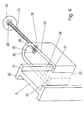
- a mounting system 1 for solar modules comprises a frame 2, which consists of upwardly directed profiles 3 and horizontal profiles 4 and 5, wherein in FIG. 1 only an upper horizontal profile 4 and a lower horizontal profile 5 are shown. In the middle region, further horizontal profiles can be arranged.
- On the frame 2 one or more solar modules 6 are fixed, which are held on the frame 2 via strip-shaped fastening means 12.
- the frame 2 is supported on the bottom side by a substructure, which almost completely removes the weight loads of the frame 2 with the solar modules 6.
- the substructure comprises a bottom part 11 and a fixed part 9 fixed to a pile post 7 anchored in the soil 8 ( FIG. 2 ).
- the frame 2 is fixed at spaced locations via anchors 13 on a wall 17 or facade of a building.
- the frame 2 can also extend over greater heights, for example over 4 m, and be mounted on the walls of industrial halls.
- the bottom part is arranged at a distance from the wall 17 of the building, wherein the angle of inclination may be in a range between 60 ° and 80 °, for example.
- the wall 17 of the building comprises an insulation 14, which is arranged adjacent to an inner wall 15.
- In the interior of a post 16 is arranged, which is necessary for the statics and on which an anchor 13 can be set. It is possible to provide an abutment for the armature 13 in the interior.
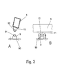
- a bottom part 11 is shown, which is designed as a tab which is welded to a bottom-side cross member 5.
- the bottom part 11 comprises an opening 92, through which an axle 10 can be pushed through.
- a fixed part 9 is provided, which is formed from two tabs, which also have an opening 91 for the passage of the axis 10.
- the two tabs are connected to each other via a mounting plate 90 and welded there.
- the mounting plate 90 may be fixed to a pedestal, such as concrete, or a post
- FIG. 4 the holder for a upwardly in the inclination angle ⁇ extending post 3 is shown, which is designed as a double-T-profile and correspondingly comprises two laterally projecting webs 30 and 31 on opposite sides, which are interconnected via a central web 32.
- the profile 3 is slidably mounted via a holder 20, which is U-shaped and has two legs 25 and 26 which are connected to one another at a bottom 27.
- a threaded rod anchor 35 is provided, which is fixed to a post 16 of the building or to another component of the building.
- a seal 29 is fixed to the armature 35 via a nut 28.
- the holder 20 is also fixed by nuts 28 in the desired position.
- the profile 3 In order to store the profile 3 displaceable, are on the legs 25 and 26 inwardly directed Webs 21 and 22 and a connecting web 24 is formed, which engage around the webs 30 and 31 on the profile 3.
- the central web 32 is performed through a slot 23 between the webs 21 and 22.
- the bottom 27 is rounded and accordingly the slot 36 is also arcuate.
- the holding part 20 can be pivoted relative to the armature 35 in order to align the profile 3 and thus the frame 2 with the solar modules 6.
- the pivot axis extends perpendicular to the longitudinal axis of the rod-shaped armature 35.
- a certain adjustment can be made about an axis perpendicular to the slot 36 via appropriate inclined washers under the nuts 28.
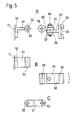
- FIGS. 5A to 5C a further embodiment of a multi-part retaining element is shown to set a frame 2 on a wall 17 of a building.
- a first anchor part 50 is fixed to a wall 17 shown schematically and comprises a protruding portion 51, on which a sleeve 52 is arranged to form a rotation axis 53.
- a second sleeve 54 of a second anchor member 50 ' is fixed via an axis, not shown, which has on the opposite side a sleeve 55 which is penetrated by an axis 56.
- a sleeve 58 of a third anchor member 50 " is fixed, which is also penetrated by the axis 56, wherein the second anchor member 50 'and the third anchor member 50" are secured to each other via nuts 57 on the axis 56 to each other.
- a guide element 59 with grooves 60 for inserting a section of a profile 3 is arranged on the third anchor part 50 ", so that the third anchor part 50" forms a retaining part for the displaceable mounting of the profile 3.
- the fixation of the sleeves 52 and 54 can be made as in the sleeves 55 and 58, so that the third anchor member 50 "is mounted both on a horizontal axis and about a vertical axis pivotally mounted on the first anchor member 50.
- an extension member 61 which has at opposite ends openings 62 and 63, can be inserted into the corresponding axes.
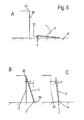
- FIGS. 6A to 6C the assembly of a mounting system according to the invention is shown schematically.
- a ramming post 7 is mounted in the ground 8, to which a fixed part 9 of the bottom part is fixed.
- a profile 3 is fixed, which lies on the ground and at the bottom with other profiles 3 by horizontal profiles 4 and 5 to a frame 2 is connectable.
- the frame 2 can then be positioned spaced from the ground in an intermediate position to mount the solar modules 6 to the frame 2.
- the necessary anchors 35 are determined on a wall 17 of the building.
- a holding part 20, 20 'or the third anchor part 59' is pushed onto the profile 3 and fixed to the anchor 35.
- the post 3 and thus also the solar modules 6 is inclined at an angle ⁇ to the vertical.
- the angle of inclination ⁇ can be chosen to be somewhat larger or smaller, depending on the season, preferably between 10 and 30 °.
- FIG. 7 a building with several assembled solar modules 6 is shown schematically on the mounting systems according to the invention. Since the frame 2 is pivotally mounted on the bottom part, the inclination angle ⁇ can be adjusted. In addition, it is also possible to align the solar modules 6 at an angle to the plane of a wall 17 of the building, as shown on the right part of the illustration. For this purpose, for example, a multi-part armature 50, 50 'and 50 "is used, which allows a corresponding optimized orientation for attachment of the solar modules 6.
- FIG. 8 schematically a length-adjustable anchor 35 'is shown, in which a rod-shaped threaded portion 36' is provided centrally with a tool attachment 37 'and is screwed on opposite sides in a sleeve 38'.
- a connection point 39' is provided on the sleeve 38 'is a connection point 39' is provided so that the armature 35 'on a wall 17 of a building or with a holder 20, 20' or 40 can be connected. Due to the change in length of the armature 35 ', the inclination angle of the solar modules can be adjusted.
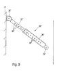
- FIG. 9 A modified embodiment of an anchor 35 "is shown, which is also adjustable in length, for this purpose a rod 37" engages a sleeve 36 ", wherein both the rod 37" and the sleeve 36 “openings 38" are formed , which can then be penetrated by appropriate pins for fixation.
- the holding parts 20, 20 ', 59 are each mounted on a profile 3, which is slidably mounted. It is of course also possible to mount on the frame 2 additional components that allow a sliding bearing relative to a fixed anchor
Landscapes
- Engineering & Computer Science (AREA)
- Chemical & Material Sciences (AREA)
- Mechanical Engineering (AREA)
- Sustainable Development (AREA)
- Sustainable Energy (AREA)
- Thermal Sciences (AREA)
- Physics & Mathematics (AREA)
- Combustion & Propulsion (AREA)
- Life Sciences & Earth Sciences (AREA)
- General Engineering & Computer Science (AREA)
- Architecture (AREA)
- Civil Engineering (AREA)
- Structural Engineering (AREA)
- Photovoltaic Devices (AREA)
- Roof Covering Using Slabs Or Stiff Sheets (AREA)
Applications Claiming Priority (1)
| Application Number | Priority Date | Filing Date | Title |
|---|---|---|---|
| DE202010005249U DE202010005249U1 (de) | 2010-04-19 | 2010-04-19 | Montagesystem für Solarmodule |
Publications (1)
| Publication Number | Publication Date |
|---|---|
| EP2378564A2 true EP2378564A2 (fr) | 2011-10-19 |
Family
ID=42283091
Family Applications (1)
| Application Number | Title | Priority Date | Filing Date |
|---|---|---|---|
| EP11162349A Withdrawn EP2378564A2 (fr) | 2010-04-19 | 2011-04-14 | Système de montage pour module solaire |
Country Status (3)
| Country | Link |
|---|---|
| US (1) | US20110266233A1 (fr) |
| EP (1) | EP2378564A2 (fr) |
| DE (1) | DE202010005249U1 (fr) |
Families Citing this family (1)
| Publication number | Priority date | Publication date | Assignee | Title |
|---|---|---|---|---|
| DE102021004261B3 (de) | 2021-08-20 | 2023-02-02 | Oliver Kessler Design Gmbh | LED-Beleuchtungselemente, die in ihre verschiedenen Komponenten zerlegbar und aufrollbar sind |
Family Cites Families (18)
| Publication number | Priority date | Publication date | Assignee | Title |
|---|---|---|---|---|
| US6111189A (en) * | 1998-07-28 | 2000-08-29 | Bp Solarex | Photovoltaic module framing system with integral electrical raceways |
| DE19934073B4 (de) * | 1999-07-19 | 2005-08-25 | Regen Energiesysteme Gmbh | Vorrichtung zur Befestigung von Solarmodulen |
| US6360491B1 (en) * | 2000-01-14 | 2002-03-26 | Stanley A. Ullman | Roof support system for a solar panel |
| JP2002141541A (ja) * | 2000-10-31 | 2002-05-17 | Canon Inc | 太陽光発電装置および建造物 |
| WO2002041407A1 (fr) * | 2000-11-16 | 2002-05-23 | Kaneka Corporation | Module de batterie solaire, systeme de production d'energie photovoltaique, bloc de support supportant ce module de batterie solaire, et procede d'installation d'un systeme de production d'energie photovoltaique |
| US6534703B2 (en) * | 2001-07-10 | 2003-03-18 | Powerlight Corporation | Multi-position photovoltaic assembly |
| US7434362B2 (en) * | 2001-07-20 | 2008-10-14 | Unirac, Inc. | System for removably and adjustably mounting a device on a surface |
| US6722357B2 (en) * | 2001-08-15 | 2004-04-20 | Powerlight Corporation | Fixed angle solar collector arrangement |
| US20030154667A1 (en) * | 2002-02-20 | 2003-08-21 | Dinwoodie Thomas L. | Shingle system |
| WO2003087493A1 (fr) * | 2002-04-11 | 2003-10-23 | Rwe Schott Solar Inc. | Appareil et procede d'installation de systemes de generation d'energie photovoltaique sur des batiments |
| US7600349B2 (en) * | 2003-02-26 | 2009-10-13 | Unirac, Inc. | Low profile mounting system |
| US6959517B2 (en) * | 2003-05-09 | 2005-11-01 | First Solar, Llc | Photovoltaic panel mounting bracket |
| US7592537B1 (en) * | 2004-02-05 | 2009-09-22 | John Raymond West | Method and apparatus for mounting photovoltaic modules |
| US7856769B2 (en) * | 2004-02-13 | 2010-12-28 | Pvt Solar, Inc. | Rack assembly for mounting solar modules |
| US7297866B2 (en) * | 2004-03-15 | 2007-11-20 | Sunpower Corporation | Ventilated photovoltaic module frame |
| US7406800B2 (en) * | 2004-05-18 | 2008-08-05 | Andalay Solar, Inc. | Mounting system for a solar panel |
| ES2293602T3 (es) * | 2005-01-10 | 2008-03-16 | Conergy Ag | Sistema de montaje con corredera roscada. |
| US8813460B2 (en) * | 2007-09-21 | 2014-08-26 | Andalay Solar, Inc. | Mounting system for solar panels |
-
2010
- 2010-04-19 DE DE202010005249U patent/DE202010005249U1/de not_active Expired - Lifetime
-
2011
- 2011-04-14 EP EP11162349A patent/EP2378564A2/fr not_active Withdrawn
- 2011-04-19 US US13/089,551 patent/US20110266233A1/en not_active Abandoned
Non-Patent Citations (1)
| Title |
|---|
| None |
Also Published As
| Publication number | Publication date |
|---|---|
| US20110266233A1 (en) | 2011-11-03 |
| DE202010005249U1 (de) | 2010-06-24 |
Similar Documents
| Publication | Publication Date | Title |
|---|---|---|
| DE102013210186B4 (de) | Aufständerungssystem für Solarpaneele | |
| WO2020049374A1 (fr) | Ferrure d'ajustage et système de support pour modules solaires | |
| DE20319065U1 (de) | Solaranordnung mit einer Tragkonstruktion für ein oder mehrere Solarmodule | |
| EP2378221A2 (fr) | Système de montage pour modules solaires et procédé de montage d'une installation solaire | |
| EP2378563A2 (fr) | Système de montage pour module solaire | |
| EP2186964B1 (fr) | Recouvrement avec au moins deux tôles métalliques entre des profilés et installation solaire sur ce recouvrement | |
| DE102017003694B4 (de) | Bausatz zur Errichtung einer Unterkonstruktion für Terrassenlaufflächen | |
| WO2019191796A1 (fr) | Dispositif et procédé de construction d'un bassin de piscine | |
| WO2013139745A2 (fr) | Dispositif de mise à jour pour modules solaires | |
| DE102005032859B3 (de) | Befestigungssystem für Solarmodule | |
| EP4291720B1 (fr) | Élément de protection de talus | |
| EP3216942A1 (fr) | Système de structure de plancher | |
| EP2378564A2 (fr) | Système de montage pour module solaire | |
| DE202010010140U1 (de) | Perfektionierte schwenkbare Stütze für Solarpaneele | |
| DE202006009884U1 (de) | Unterkonstruktion für PV-Anlage | |
| EP1785546A1 (fr) | Console ancrable pour la fixation du revêtement d'un mur de bâtiment | |
| EP3290612B1 (fr) | Dispositif formant toit et procédé de fabrication d'un dispositif formant toit | |
| DE9409626U1 (de) | Balkonkonstruktion | |
| DE202012005413U1 (de) | Ausrichtbares Fundamentsystem für Solarpaneele | |
| DE202014100961U1 (de) | Solarmodulsystem | |
| EP1033454A2 (fr) | Elément de construction pour armature de cisaillement | |
| DE102011104455B4 (de) | Baugruppe eines Ständers für PV-Module, Halteaufsatz und Verfahren zum Montieren der Baugruppe | |
| DE102018203080B4 (de) | Fundamentsystem für die lagerung von flächig nebeneinander angeordneten solarpaneelen | |
| EP3786385B1 (fr) | Elément en forme de fourche pour utilisation dans une structure de fixation à nombre réduit de composants | |
| DE102023005386B4 (de) | Bausatz zur Aufständerung von Solarmodulen |
Legal Events
| Date | Code | Title | Description |
|---|---|---|---|
| AK | Designated contracting states |
Kind code of ref document: A2 Designated state(s): AL AT BE BG CH CY CZ DE DK EE ES FI FR GB GR HR HU IE IS IT LI LT LU LV MC MK MT NL NO PL PT RO RS SE SI SK SM TR |
|
| AX | Request for extension of the european patent |
Extension state: BA ME |
|
| PUAI | Public reference made under article 153(3) epc to a published international application that has entered the european phase |
Free format text: ORIGINAL CODE: 0009012 |
|
| STAA | Information on the status of an ep patent application or granted ep patent |
Free format text: STATUS: THE APPLICATION IS DEEMED TO BE WITHDRAWN |
|
| 18D | Application deemed to be withdrawn |
Effective date: 20131101 |