EP2381055A2 - Serrure pour un élément de fermeture - Google Patents
Serrure pour un élément de fermeture Download PDFInfo
- Publication number
- EP2381055A2 EP2381055A2 EP11003409A EP11003409A EP2381055A2 EP 2381055 A2 EP2381055 A2 EP 2381055A2 EP 11003409 A EP11003409 A EP 11003409A EP 11003409 A EP11003409 A EP 11003409A EP 2381055 A2 EP2381055 A2 EP 2381055A2
- Authority
- EP
- European Patent Office
- Prior art keywords
- lock
- latch
- drive
- door
- bolt
- Prior art date
- Legal status (The legal status is an assumption and is not a legal conclusion. Google has not performed a legal analysis and makes no representation as to the accuracy of the status listed.)
- Granted
Links
- 230000033001 locomotion Effects 0.000 claims abstract description 24
- 230000005540 biological transmission Effects 0.000 description 14
- 238000012806 monitoring device Methods 0.000 description 10
- 238000012544 monitoring process Methods 0.000 description 8
- 230000006870 function Effects 0.000 description 7
- 239000004020 conductor Substances 0.000 description 5
- 238000005553 drilling Methods 0.000 description 4
- 230000008859 change Effects 0.000 description 3
- 230000006378 damage Effects 0.000 description 3
- 238000001514 detection method Methods 0.000 description 3
- 230000000694 effects Effects 0.000 description 3
- 238000009434 installation Methods 0.000 description 3
- 230000008901 benefit Effects 0.000 description 2
- 238000006243 chemical reaction Methods 0.000 description 2
- 230000008878 coupling Effects 0.000 description 2
- 238000010168 coupling process Methods 0.000 description 2
- 238000005859 coupling reaction Methods 0.000 description 2
- 230000009467 reduction Effects 0.000 description 2
- 238000009420 retrofitting Methods 0.000 description 2
- 238000005096 rolling process Methods 0.000 description 2
- 238000010276 construction Methods 0.000 description 1
- 230000007423 decrease Effects 0.000 description 1
- 230000000881 depressing effect Effects 0.000 description 1
- 238000007599 discharging Methods 0.000 description 1
- 238000006073 displacement reaction Methods 0.000 description 1
- 238000009429 electrical wiring Methods 0.000 description 1
- 230000007613 environmental effect Effects 0.000 description 1
- 230000036039 immunity Effects 0.000 description 1
- 230000010354 integration Effects 0.000 description 1
- 230000010355 oscillation Effects 0.000 description 1
- 230000036316 preload Effects 0.000 description 1
- 230000002035 prolonged effect Effects 0.000 description 1
- 238000003466 welding Methods 0.000 description 1
Images

Classifications
-
- E—FIXED CONSTRUCTIONS
- E05—LOCKS; KEYS; WINDOW OR DOOR FITTINGS; SAFES
- E05B—LOCKS; ACCESSORIES THEREFOR; HANDCUFFS
- E05B15/00—Other details of locks; Parts for engagement by bolts of fastening devices
- E05B15/10—Bolts of locks or night latches
-
- E—FIXED CONSTRUCTIONS
- E05—LOCKS; KEYS; WINDOW OR DOOR FITTINGS; SAFES
- E05B—LOCKS; ACCESSORIES THEREFOR; HANDCUFFS
- E05B47/00—Operating or controlling locks or other fastening devices by electric or magnetic means
- E05B47/0001—Operating or controlling locks or other fastening devices by electric or magnetic means with electric actuators; Constructional features thereof
- E05B47/0012—Operating or controlling locks or other fastening devices by electric or magnetic means with electric actuators; Constructional features thereof with rotary electromotors
-
- E—FIXED CONSTRUCTIONS
- E05—LOCKS; KEYS; WINDOW OR DOOR FITTINGS; SAFES
- E05B—LOCKS; ACCESSORIES THEREFOR; HANDCUFFS
- E05B47/00—Operating or controlling locks or other fastening devices by electric or magnetic means
- E05B47/02—Movement of the bolt by electromagnetic means; Adaptation of locks, latches, or parts thereof, for movement of the bolt by electromagnetic means
- E05B47/026—Movement of the bolt by electromagnetic means; Adaptation of locks, latches, or parts thereof, for movement of the bolt by electromagnetic means the bolt moving rectilinearly
-
- E—FIXED CONSTRUCTIONS
- E05—LOCKS; KEYS; WINDOW OR DOOR FITTINGS; SAFES
- E05B—LOCKS; ACCESSORIES THEREFOR; HANDCUFFS
- E05B47/00—Operating or controlling locks or other fastening devices by electric or magnetic means
- E05B47/0001—Operating or controlling locks or other fastening devices by electric or magnetic means with electric actuators; Constructional features thereof
- E05B2047/0014—Constructional features of actuators or power transmissions therefor
- E05B2047/0015—Output elements of actuators
- E05B2047/0016—Output elements of actuators with linearly reciprocating motion
-
- E—FIXED CONSTRUCTIONS
- E05—LOCKS; KEYS; WINDOW OR DOOR FITTINGS; SAFES
- E05B—LOCKS; ACCESSORIES THEREFOR; HANDCUFFS
- E05B47/00—Operating or controlling locks or other fastening devices by electric or magnetic means
- E05B47/0001—Operating or controlling locks or other fastening devices by electric or magnetic means with electric actuators; Constructional features thereof
- E05B2047/0014—Constructional features of actuators or power transmissions therefor
- E05B2047/0018—Details of actuator transmissions
- E05B2047/002—Geared transmissions
-
- E—FIXED CONSTRUCTIONS
- E05—LOCKS; KEYS; WINDOW OR DOOR FITTINGS; SAFES
- E05B—LOCKS; ACCESSORIES THEREFOR; HANDCUFFS
- E05B47/00—Operating or controlling locks or other fastening devices by electric or magnetic means
- E05B47/0001—Operating or controlling locks or other fastening devices by electric or magnetic means with electric actuators; Constructional features thereof
- E05B2047/0014—Constructional features of actuators or power transmissions therefor
- E05B2047/0018—Details of actuator transmissions
- E05B2047/0026—Clutches, couplings or braking arrangements
- E05B2047/0031—Clutches, couplings or braking arrangements of the elastic type
-
- E—FIXED CONSTRUCTIONS
- E05—LOCKS; KEYS; WINDOW OR DOOR FITTINGS; SAFES
- E05B—LOCKS; ACCESSORIES THEREFOR; HANDCUFFS
- E05B47/00—Operating or controlling locks or other fastening devices by electric or magnetic means
- E05B2047/0048—Circuits, feeding, monitoring
- E05B2047/0057—Feeding
- E05B2047/0058—Feeding by batteries
-
- E—FIXED CONSTRUCTIONS
- E05—LOCKS; KEYS; WINDOW OR DOOR FITTINGS; SAFES
- E05B—LOCKS; ACCESSORIES THEREFOR; HANDCUFFS
- E05B47/00—Operating or controlling locks or other fastening devices by electric or magnetic means
- E05B2047/0048—Circuits, feeding, monitoring
- E05B2047/0057—Feeding
- E05B2047/0062—Feeding by generator
-
- E—FIXED CONSTRUCTIONS
- E05—LOCKS; KEYS; WINDOW OR DOOR FITTINGS; SAFES
- E05B—LOCKS; ACCESSORIES THEREFOR; HANDCUFFS
- E05B47/00—Operating or controlling locks or other fastening devices by electric or magnetic means
- E05B2047/0084—Key or electric means; Emergency release
-
- E—FIXED CONSTRUCTIONS
- E05—LOCKS; KEYS; WINDOW OR DOOR FITTINGS; SAFES
- E05B—LOCKS; ACCESSORIES THEREFOR; HANDCUFFS
- E05B47/00—Operating or controlling locks or other fastening devices by electric or magnetic means
- E05B2047/0084—Key or electric means; Emergency release
- E05B2047/0086—Emergency release, e.g. key or electromagnet
- E05B2047/0087—Electric spare devices, e.g. auxiliary batteries or capacitors for back up
-
- E—FIXED CONSTRUCTIONS
- E05—LOCKS; KEYS; WINDOW OR DOOR FITTINGS; SAFES
- E05B—LOCKS; ACCESSORIES THEREFOR; HANDCUFFS
- E05B45/00—Alarm locks
- E05B45/06—Electric alarm locks
- E05B45/08—Electric alarm locks with contact making inside the lock or in the striking plate
- E05B45/12—Electric alarm locks with contact making inside the lock or in the striking plate by movement of the bolt
-
- E—FIXED CONSTRUCTIONS
- E05—LOCKS; KEYS; WINDOW OR DOOR FITTINGS; SAFES
- E05B—LOCKS; ACCESSORIES THEREFOR; HANDCUFFS
- E05B59/00—Locks with latches separate from the lock-bolts or with a plurality of latches or lock-bolts
Definitions
- the invention relates to a lock for a locking part, in particular door lock, with a latch and / or with a lock bolt, and with a drive motor having at least one drive unit for a motorized adjustment of the latch and / or the lock bolt between an open position and a closed position, wherein the Lock latch and the lock bolt are each designed as a closing part for engaging in an opening in a strike plate or the like of a frame or wall.
- door locks usually have a lockable with the key and lockable latch and a spring-loaded or spring-biased latch. While the latch is used to securely close the door, the latch has the task of the unlocked door in a "door-to-hold" position (closed position), this lock latch is usually bevelled so that they first against the closing of the door Spring force is pressed into the lock housing and then spring-loaded is zuriiekverschoben in the closed position, so that it engages in a recess of the opposite side lying on the frame side striker and thereby holds the door firmly.
- a door opener for a door wherein the door opener has a drive unit, with the door closed, a motor release of the lock latch is effected by the strike plate.
- the drive unit is configured in such a way that, for the opening release, the latch is displaceable against the spring preload by the drive unit out of engagement with the strike plate.
- the drive unit causes the ⁇ ffhungskegabe exactly the adjustment, which can be effected in known door locks by the manual operation of a door handle.
- the drive unit can be assigned to the strike plate and arranged behind the strike plate in a cutout, wherein the latch bolt is pushed out of the strike plate with the drive unit. Alternatively, it is possible that the drive unit is associated with the door lock and the latch is pulled out of the strike plate at the motor opening release.
- the drive unit may comprise an electric motor having on its drive shaft a worm, which is in engagement with a gear, with which an eccentric is connected.
- the movement of the eccentric leads to the movement of an actuating element for adjusting the latch between a closed position and an opening release position.
- the electrical supply to the electric motor via the connection to AC mains voltage.
- Object of the present invention is to develop a lock of the type described above and specify that is improved in terms of design and functionality.
- a lock for a locking part in particular a door lock
- a latch and / or with a lock bolt and with a drive unit having at least one drive motor for a motorized adjustment of the latch and / or the lock bolt between an open position and a closed position and in particular to achieve a small size of the lock
- the drive motor integrated into the latch or in the lock bolt and together with the latch or lock bolt and relative to a lock case or housing of the lock according to the invention between the open position and the closed position is adjustable or movable.
- the latch and the latch engage as engagement members in the closed position in an opening of the closure member or the door adjacent frame or wall and thus prevent the opening of the Verschoudreteils.
- the latch and the latch bolt may each have a separate drive motor, which is an integral part of the latch or the lock bolt.
- the integration of the drive motor in the latch or in the lock bolt leads to a significant reduction in the size of the door lock, with a simple installation and removal of the drive motor together
- the drive motor is received without damage in the lock latch or the lock bolt, which ensures a high immunity to interference of the lock according to the invention with the lock latch or the lock bolt.
- the drive motor for adjusting the latch or the lock bolt may optionally be mechanically coupled via a gear with at least one power transmission means and cooperate to effect an adjustment of the latch or the lock bolt can.
- the transmission may also be an integral part of the latch or lock bolt, such as the drive motor.
- the drive motor may have a drive pinion driven in rotation, which engages in a toothed rack fixed or formed on a lock case or a housing of the lock. The drive motor is fixed to the latch or on the lock bolt, so that by adjusting the drive pinion in a simple manner an adjustment of the latch or the lock bolt in the longitudinal direction of the rack is possible.
- the drive motor is preferably designed as an electric motor, in particular as a DC or stepper motor, wherein the list is not exhaustive.
- the invention further relates to a lock for a closing part, in particular a door lock, with a lock latch and / or with a lock bolt, with a drive unit having at least one electric drive motor for an electromotive adjustment or movement of the lock latch and / or the lock bolt and with an actuating means , in particular a door handle or a door handle, for the manual adjustment of the lock latch and / or the lock bolt while performing mechanical work, wherein the latch bolt and / or the latch bolt, if necessary with the drive unit and / or with the actuating means between an open position and a closed position is movable or . are.
- the present invention relates to a drive for a closing part for the electromotive adjustment or movement of the Verschoudreteils between an open position and a closed position for closing or opening a
- the dimensions of the Verschoudreteils can substantially correspond to the dimensions of the opening, in particular a door drive for a door leaf of a door, further in particular a swing door, with at least one electric drive motor and at least one force transmitting to the drive motor power transmission element, in particular at least one friction wheel wherein the force transmission element is in frictional contact during the adjustment of the Verschierteils with a swept during adjustment of the Verschierteils wall, floor or ceiling surface and wherein in the electromotive adjustment of the Verschierteils electrical drive energy of the drive motor is converted into mechanical energy,
- the invention relates a lock arrangement with a lock and with a drive.
- an apparatus for closing an opening which comprises at least one closing part whose dimensions essentially correspond to the dimensions of the opening and at least one drive means for moving the closing part.
- the drive means has a rotatably driven axle, which carries at least one substantially wheel-shaped rolling body or a friction wheel, wherein the drive means is mounted in or on the edge region of the Verschierteils in such a way that the rolling body in frictional contact with the during opening of the Closing device over painted floor, wall or ceiling surface is.
- drive means AC, DC or stepper motors can be used, wherein the power supply of the drive means preferably from an accumulator or a battery, optionally in conjunction with a provided on the door surface or a drive means housing solar cell can take place. But it can also be done from the mains.
- hydraulically actuated motors can be used.
- live conductors are required, for example via the closing part, such as a door leaf, or a frame for the closing part or the wall over a door frame, lead to the lock and the drive and connect the lock or the drive to the mains.
- the required electrical connection via live conductors to a power network complicates the retrofitting of locking parts, such as doors, with a lock and / or a drive of the type described above.
- failure of the power supply is a power supply to the drive unit of the castle or the drive for the Locking part not guaranteed.
- Object of the present invention is therefore also to develop a lock and a drive in each case of the type described above and to provide a lock and a drive, which are improved in terms of structure and functionality. Furthermore, a lock assembly with a lock and a drive in terms of design and functionality should be improved.
- the lock has an electric generator and is operatively connected to the actuating means such that the performed during an actuation of the actuating means mechanical work with the generator into electrical energy for powering the drive motor is feasible.
- the lock according to the invention has a generator or dynamo in order to enable independent operation of the drive unit for adjusting the lock latch and / or the lock bolt, regardless of the connection to mains AC voltage, wherein the required for operation of the drive unit electrical drive energy by performing mechanical work at (Previous) operation of the actuating means, for example, when turning a door handle or when depressing a door handle, and the conversion is provided with the generator.
- At least one internal or the lock associated battery / accumulator arrangement for temporary storage of the electrical energy generated upon actuation of the actuating means may be provided, wherein the battery / Akkuan Aunt is connected to the generator.
- the battery / accumulator arrangement can be charged by single or multiple actuation of the actuating means. It is understood that the battery / accumulator arrangement can be made replaceable.
- a Akkuansscnies be provided in which by regular charging and discharging of the battery, a long life of the battery is ensured.
- a controller may be provided which is designed such that upon connection of the lock according to the invention to a mains AC voltage, the drive power for the drive unit is primarily or exclusively taken from the mains, wherein in case of failure of the mains supply current to the drive motor for the latch and / or the lock bolt can be made via a rechargeable via the generator battery / Akkuan nie.
- the lock may further comprise a controller for the drive unit, which may be preferably designed as control electronics.
- the Steuenngektrektronik can be arranged for example on a circuit board in a lock case or in a lock housing.
- the lock latch and / or the lock bolt can be released by means of the control electronics in order subsequently to be able to make the opening of the closure part manually or automatically with a drive.
- the controller may be structured such that one part of the controller controls the lock and another part of the controller drives the closing part.
- the control electronics is on the EP 1 643 065 A2
- a drive of the type mentioned may be provided to solve the above problem that an electric generator is provided and is operatively connected to the power transmission element and / or at least one other power transmission element, wherein the case of a manual adjustment or movement of the Verschoudreteils done mechanical work with the generator is converted into electrical energy to power the drive motor.
- a dynamo function of the drive according to the invention serves to be able to effect the adjustment of the Verschoudreteils regardless of the power supply of the drive motor via a network connection.
- at least one internal battery / accumulator arrangement it is possible for at least one internal battery / accumulator arrangement to be provided for temporarily storing the electrical energy generated during manual movement of the closing part.
- an interface for connection to an AC mains voltage of a power grid and / or for connection to a further battery / Akkuan angel be provided to supply the drive motor of the drive regardless of the manual movement of the Verschhneteils with energy.
- a second power transmission element for example, a second friction wheel
- a second friction wheel is provided, which is operatively connected to the generator in order to convert the work done in a manual closing and opening of the Verschhneteils work into electrical energy can.
- the second friction wheel is also in frictional contact with a swept during adjustment of the Verschoudreteils wall, floor or ceiling surface.
- the drive motor and the second power transmission element are then preferably not coupled, wherein a slip clutch between the drive motor and the first power transmission element (first friction wheel) can be arranged so that a manual adjustment of the Verschhneteils remains without affecting the drive motor.
- the lock according to the invention and the drive according to the invention can be realized in a lock arrangement.
- the electrical energy generated during a manual movement of the closing part with the generator of the drive for the closing part can also or only be used to supply power to the drive motor of the lock for adjusting the lock latch and / or the lock bolt, resulting in a corresponding connection of the drive for requires the Vexschbeck with the lock via an electrical line.
- the electrical wiring can be done for example via a door leaf of a door when a door lock to be electrically connected to a door drive.
- the invention further relates to a lock assembly with a drive for a motorized adjustment of a Verschoudreteils between an open position and a closed position for closing an opening, wherein the dimensions of the Verschoudreteils correspond substantially to the dimensions of the opening, in particular with a door drive for a door leaf of a door, in particular a swing door, with at least one lock, in particular a door lock, and with at least one controller, the drive having at least one drive motor and at least one power transmission element coupled to the drive motor, in particular at least one friction wheel, wherein the force transmission element during the adjustment of the closing part is in frictional contact with a swept over during the adjustment of the closing part wall, floor or ceiling surface, wherein in the motorized adjustment of the closing part drive energy of the drive motor is converted into mechanical energy and wherein the lock a latch and / or a Has lock bolt and at least one drive motor for a motorized adjustment of the lock latch and / or the lock bolt between an open position and a closed position.
- frictional forces are to be overcome, for example, between the contacting surfaces of latch or latch bolt and a strike plate on a wall, a floor or a ceiling, for example on the frame of a door occur.
- these frictional forces can reach a size which does not or only to a limited extent permit an adjustment of the lock latch and / or of the lock bolt with the drive motor of the lock.
- the control is designed such that an operation of the drive motor for the closing part is provided during the motorized adjustment of the lock latch and / or the lock bolt, in particular for Generation of an adjusting force acting in the closing direction of the closing part.
- the invention relates to a lock for a locking part, in particular a door lock, with a latch and / or with a lock bolt, preferably with a drive motor having at least one drive unit for a motorized adjustment of the latch and / or the lock bolt.
- the latch and / or the lock bolt between two positions back and forth adjust, in an open position, the locking part is released and the latch or lock bolt no contact with the strike plate and (completely ) are retracted.
- the latch and / or the latch bolt are preferably fully extended and are in contact with the strike plate, wherein the latch or the latch bolt are held by the strike plate and can engage in a recess of the strike plate ("door-to-position") ,
- the automatic monitoring of the position of the lock latch and / or the lock bolt which can be done by a corresponding control electronics with monitoring function, can not be determined easily due to the position of the lock latch and / or the lock bolt, whether the locking member actually in an open position ("door-to-position") or in a closed position (“door-to-position”) is arranged.
- the latch and / or the lock bolt can also be in a closed position, if the door is not held in the "door-off position", but for example from the outside against the door frame or the frame inspired. This condition may occur if the door has not been properly closed prior to adjustment of the latch or latch to the closed position.
- the invention proposes a lock of the type described above, the at least one position determination device designed to determine the position of the lock latch and / or the lock bolt in an open position and / or in a closed position and in at least one other position.
- the at least one further position can be detected, in which, for example, the latch and / or the lock bolt can be extended further than in the closed position.
- the permissible end position of the lock latch and / or the lock bolt can be predetermined by the structural design of the strike plate.
- a position determination of the latch and / or the lock bolt is continuously or discontinuously possible after reaching a certain position of the latch or the lock bolt.
- the position determination may be part of a monitoring device, wherein in a change in the position of the latch or the lock bolt on a manipulation of the castle, for example in the event of a burglary, can be closed.
- the monitoring device can be used to automatically transmit position values and / or alarm signals to a central receiving device be formed, the data transmission can preferably be done via radio.
- the monitoring device can also be designed to evaluate measured or detected actual positions of the latch bolt and lock bolt by comparison with stored desired positions in the open position and the closed position. Target positions can be recorded manually after installation of the lock and stored in a storage device.
- the monitoring device can also have a learning function, by means of which various desired positions of the latch or the lock bolt can be detected and then stored in a memory device.
- the above-described functions may be part of a corresponding electronics, which may include the control of the drive unit for motorized adjustment of latch and lock bolt.
- a monitoring device may be provided for monitoring at least one physical state variable of the lock or a component thereof, wherein the monitoring device has at least one monitoring means for detecting or for measuring value detection a deviation of the actual value of the physical state variable is formed by a predetermined desired value of the state variable.
- the deviation may be, for example, the result of a non-functional force from the outside on the lock, which may lead to a deviation, for example, when drilling the lock case.
- the invention is based on the basic idea of being able to reliably and reliably detect manipulation of the lock or its components by determining and monitoring the values of physical state variables or parameters of the components of the lock.
- the state variables may, for example, be position coordinates, frequencies and amplitudes of vibrations or oscillations, temperatures and / or current conductivity, the enumeration being not exhaustive.
- At least one sensor preferably a motion sensor and / or position detection sensor for detecting a movement and / or the position of, for example, the lock latch and / or the lock bolt
- Vibration sensor for detecting vibrations of the lock case or the housing
- a temperature sensor for detecting temperatures in or on the lock case or housing
- a sensor for detecting air vibrations to be provided may also be provided in the lock box integrated circuit board and / or individual conductor tracks, wherein an interruption of at least one conductor track, for example by drilling the lock case from the outside and piercing the circuit board, as change or deviation of the current conductivity is detected.
- the monitoring device can be designed for the automatic transmission of (alarm) signals to a receiving device outside of the lock case in order to be able to send an alarm or error message to a security center or the like in the event of a detected deviation.
- the lock according to the invention contributes greatly to burglary protection.
- the monitoring device can also have a self-test function, which continuously or discontinuously acquires the actual values of the state variables and compares them with desired values.
- FIG. 1 schematically a lock assembly 1 with a door lock 2 and a door drive 3 is shown.
- the door lock 2 and the door drive 3 can be attached to a door leaf 4 of the door or inserted into the door leaf 4.
- the door lock 2 has a latch 5 and a lock bolt 6.
- the latch 5 is spring-loaded or spring-biased and has the task to hold the unlocked door in a "door-to-position", wherein it engages in a recess of a opposite lying on a frame side locking plate, thereby holding the door.
- the lock bolt 6 is used to securely close the door.
- other components may be provided, which are not shown in detail.
- the door lock 2 has at least one electric drive motor having drive unit 7 for an electromotive adjustment of the latch 5 and a further drive unit 8 for electromotive adjustment of the lock bolt 6.
- the latch 5 and the lock bolt 6 can also be adjusted manually via a door handle 9 as an actuating means performing mechanical work.
- the latch 5 and the lock bolt 6 are with the drive units 7, 8 and / or with the door handle 9, if necessary, between an open position and a closed position movable back and forth.
- the door lock 2 also has an electric generator 10, which is in operative connection with the door handle 9, so that the mechanical work performed with the generator 10 in electrical energy for supplying power to the drive motors of the drive units 7, 8 can be implemented when the door handle 9 is actuated ,
- This makes it possible to perform the adjustment of the lock latch 5 and the lock bolt 6, regardless of a power grid or, AC line voltage.
- the door drive 3 is provided, which is also shown only schematically.
- the door drive 3 is integrated in the door leaf 4 or, with a corresponding housing inserted into a corresponding cutout in the door leaf 4.
- the door drive 3 has an electric drive motor 11 which is coupled to transmit force to a friction wheel 12.
- the door leaf 4 can be pivoted about a schematically illustrated vertical longitudinal axis X or between an open position in which the door is in a "door open position", and a closed position, in which the door in a "Door-to-position" is located and interacts with a door frame, not shown, adjust.
- the friction wheel 12 is in frictional contact with a swept over during adjustment floor surface, wherein the electrical drive energy for the drive motor 11 is converted into mechanical energy and the adjusting wheel 12 is transmitted an adjusting force.
- the door drive 3 also has an electric generator 13 which is in operative connection with another friction wheel 14. This makes it possible to implement the mechanical work done with the generator 13 in a manual adjustment of the door leaf 4 into electrical energy for supplying energy to the drive motor 11. It is not shown that a slip clutch can be provided between the drive motor 11 and the first friction wheel 12,
- the door lock 2 and the door drive 3 each have at least one battery / accumulator arrangement for temporarily storing the actuation of the door latch 9 or, in the case of manual movement of the door lock Door leaf 4 may have generated electrical energy.
- an interface for connection to an AC mains voltage of a power grid and / or for connecting a further battery / Akkuan ever can be provided in addition.
- the electrical energy generated by the generator 13 it is possible for the electrical energy generated by the generator 13 to be used as drive energy for the drive motors of the drive units 7, 8 of the door lock 2.
- the door lock 2 has a position determining device 15, which may be designed as a motion sensor. This makes it possible, the position of the lock latch 5 in an open position in which in the FIG. 1
- the position determining device 15 can cooperate with a monitoring device 16 which is functionalized such that the deviation of the position of the latch 5 (actual value) from a predetermined desired value at a certain position of Lock case 5 is detected, for example, to detect a manipulation or a burglary in a simple manner in a drilling of the door lock 2 from the outside and a consequent adjustment of the latch bolt 5.
- the monitoring device 16 can be configured to transmit alarm signals to a security center, for example via radio.
- a control electronics not shown in detail may be provided to implement the described functions of the door lock 2 and the door drive 3.
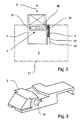
- the drive unit 7 can be integrated into the latch 5 and moved together with the latch 5 between the open position and the closed position. This is indicated by the arrow X in Fig. 2 characterized.
- the lock latch which is formed as such in one piece and forms an adjustable locking part of the lock 2, a bore 18 for receiving the drive unit 7. This results in a space-saving arrangement of the components of the lock 2 in a lock case 17 and a small size of the lock box 17th
- the drive unit 7 is designed as a geared motor with a drive part 19 and a gear part 20.
- the translation can be between 1: 500 to 1: 900, preferably about 1: 700.
- Drive part 19 and transmission part 20th are inserted into the bore 18.
- the drive unit 7, On the open side of the bore 18, the drive unit 7, a drive or motor pinion 21 which cooperates with a fixed to the lock case 17 rack 22.
- the drive unit 7 is mechanically coupled to the lock case 17 in order to convert a rotational movement of the drive motor or the drive part 19 into a linear movement of the lock catch 5 in the direction of the arrow X.
- the rack 22 is slidably mounted or guided on the lock case 17 in the manner of a carriage.
- a guide 23 or, a shaft to the lock case 17 is provided. This makes it possible to move the rack 22 also in the direction of arrow X.
- the rack 22 is spring-loaded, wherein the rack 22 against the spring load together with the latch 5 at standstill of the drive motor from the closed position towards the open position is displaceable, in the closed position, the rack 22 is supported against the lock case 17.
- the latch 5 can be moved with the drive unit 7 by electric motor between the closed position and the open position and relative to the rack 22 and thus to the lock box 17.
- an adjusting movement of the latch 5 from the closed position to the open position is possible when a compressive force acts on the latch 5 from the outside. If the pressure force is sufficiently high, the latch 5 is moved together with the rack 22 against the force acting on the rack 22 spring force toward the open position. As a result, damage to the door lock 2 is prevented.
- a slip clutch can be provided which interrupts the coupling between the drive unit 7 and the lock case 17 at a sufficiently high pressure force on the latch bolt 5.
- a possibility of movement of the latch 5 is preferably given by the closed position in the open position by actuation of a lock cylinder of the lock 2 and upon actuation of the door handle 9, as is already known from the prior art in itself.
- a storage device for electrical energy in particular a battery arrangement, can be provided.
- a charging of the storage unit can be done from the outside via a connection in particular the latch 5 to a current-carrying preferably along a frame or wall extending conductor of a power network, the latch 5 may have corresponding contacts, the electrical connection between the power grid and when closing the door the storage unit.
- the drive motor is controllable in dependence on the control of a door drive for motorized adjustment of the door between an open position and a closed position of the door.
- the controller may be configured such that the door drive can only be put into operation or, if the latch has been moved 5 from the closed position to the open position,
- the drive unit 8 Fig. 1 may be integrated into the lock bolt 6, even if this is not shown.
Landscapes
- Physics & Mathematics (AREA)
- Electromagnetism (AREA)
- Lock And Its Accessories (AREA)
Applications Claiming Priority (1)
| Application Number | Priority Date | Filing Date | Title |
|---|---|---|---|
| DE102010018221A DE102010018221A1 (de) | 2010-04-23 | 2010-04-23 | Schloss und Antrieb für ein Verschließteil und Schlossanordnung |
Publications (3)
| Publication Number | Publication Date |
|---|---|
| EP2381055A2 true EP2381055A2 (fr) | 2011-10-26 |
| EP2381055A3 EP2381055A3 (fr) | 2015-12-30 |
| EP2381055B1 EP2381055B1 (fr) | 2018-08-29 |
Family
ID=44359769
Family Applications (1)
| Application Number | Title | Priority Date | Filing Date |
|---|---|---|---|
| EP11003409.7A Not-in-force EP2381055B1 (fr) | 2010-04-23 | 2011-04-26 | Serrure pour un élément de fermeture |
Country Status (2)
| Country | Link |
|---|---|
| EP (1) | EP2381055B1 (fr) |
| DE (1) | DE102010018221A1 (fr) |
Cited By (2)
| Publication number | Priority date | Publication date | Assignee | Title |
|---|---|---|---|---|
| EP3862517A1 (fr) * | 2020-02-10 | 2021-08-11 | Schulte-Schlagbaum Aktiengesellschaft | Serrure autonome avec communication sans fil |
| CN115263089A (zh) * | 2022-08-30 | 2022-11-01 | 项城市梦远医疗科技有限公司 | 蓝牙+nb物联网智能锁 |
Families Citing this family (3)
| Publication number | Priority date | Publication date | Assignee | Title |
|---|---|---|---|---|
| DE102012017820B4 (de) | 2012-09-08 | 2025-02-06 | Gantner Electronic Gmbh | Verfahren und Vorrichtung zum Betrieb eines Schrankschlosses einer zentralen Schließanlage mit Energiegewinnung |
| DE202013005488U1 (de) * | 2013-06-19 | 2014-09-22 | Wilhelm Rademacher | Türschloss |
| DE102019104811A1 (de) | 2019-02-26 | 2020-08-27 | Stöbich Technology Gmbh | Türelement, Schließsystem und Verfahren zum Berechnen eines Wartungszeitraumes eines Türelements |
Citations (3)
| Publication number | Priority date | Publication date | Assignee | Title |
|---|---|---|---|---|
| DE9414049U1 (de) | 1994-08-30 | 1994-11-03 | Albrecht, Martin, 83109 Großkarolinenfeld | Motorbetriebene Vorrichtung zum Verschließen einer Öffnung |
| EP1643065A2 (fr) | 2004-10-04 | 2006-04-05 | Wilhelm Rademacher | Dispositif d'entraînement d'une porte |
| DE202005015982U1 (de) | 2005-09-07 | 2007-01-18 | Arca Beteiligungen Gmbh | Türöffner |
Family Cites Families (10)
| Publication number | Priority date | Publication date | Assignee | Title |
|---|---|---|---|---|
| SE445055B (sv) * | 1983-03-28 | 1986-05-26 | Beudat Emile | Lasanordning innefattande en savel manuellt som elektriskt paverkbar lasenhet |
| US5061923A (en) * | 1988-09-29 | 1991-10-29 | C & M Technology, Inc. | Computerized combination lock |
| US5410301A (en) * | 1992-11-24 | 1995-04-25 | Mas-Hamilton Group | Status monitoring system for an electronic lock |
| DE4341252A1 (de) * | 1993-12-03 | 1995-06-08 | Dieter Arndt | Schließvorrichtung einer Tür |
| DE29703559U1 (de) * | 1996-03-27 | 1997-04-30 | Hainzlmaier, Hermann, 85290 Geisenfeld | Türschloß |
| DE19738938B4 (de) * | 1996-09-16 | 2009-04-02 | Simonsvoss Technologies Ag | Schloß |
| DE19708720B4 (de) * | 1997-03-04 | 2008-05-15 | Robert Bosch Gmbh | Schloß für eine Türblatt-Zargen-Kombination |
| KR100214222B1 (ko) * | 1997-06-10 | 1999-08-02 | 김지태 | 키패드 및 카드 겸용 금고 개폐 시스템과 장치 |
| DE29906490U1 (de) * | 1999-04-08 | 1999-08-05 | Ikon AG Präzisionstechnik, 14167 Berlin | Einrichtung zur zusätzlichen mechanischen Verriegelung von Türen |
| US7025394B1 (en) * | 2005-03-23 | 2006-04-11 | Hunt Harry C | Lock system for integrating into an entry door having a vertical expanse and providing simultaneous multi-point locking along the vertical expanse of the entry door |
-
2010
- 2010-04-23 DE DE102010018221A patent/DE102010018221A1/de not_active Ceased
-
2011
- 2011-04-26 EP EP11003409.7A patent/EP2381055B1/fr not_active Not-in-force
Patent Citations (3)
| Publication number | Priority date | Publication date | Assignee | Title |
|---|---|---|---|---|
| DE9414049U1 (de) | 1994-08-30 | 1994-11-03 | Albrecht, Martin, 83109 Großkarolinenfeld | Motorbetriebene Vorrichtung zum Verschließen einer Öffnung |
| EP1643065A2 (fr) | 2004-10-04 | 2006-04-05 | Wilhelm Rademacher | Dispositif d'entraînement d'une porte |
| DE202005015982U1 (de) | 2005-09-07 | 2007-01-18 | Arca Beteiligungen Gmbh | Türöffner |
Cited By (3)
| Publication number | Priority date | Publication date | Assignee | Title |
|---|---|---|---|---|
| EP3862517A1 (fr) * | 2020-02-10 | 2021-08-11 | Schulte-Schlagbaum Aktiengesellschaft | Serrure autonome avec communication sans fil |
| CN115263089A (zh) * | 2022-08-30 | 2022-11-01 | 项城市梦远医疗科技有限公司 | 蓝牙+nb物联网智能锁 |
| CN115263089B (zh) * | 2022-08-30 | 2023-08-11 | 项城市梦远医疗科技有限公司 | 蓝牙+nb物联网智能锁 |
Also Published As
| Publication number | Publication date |
|---|---|
| EP2381055B1 (fr) | 2018-08-29 |
| EP2381055A3 (fr) | 2015-12-30 |
| DE102010018221A1 (de) | 2011-10-27 |
Similar Documents
| Publication | Publication Date | Title |
|---|---|---|
| EP2552724B1 (fr) | Mécanisme d'actionnement pour véhicule automobile | |
| EP3194695B1 (fr) | Système de poignée de portière pour un véhicule automobile | |
| DE102019107081A1 (de) | Fahrzeugtürsystem mit angetriebenem Türpräsentator und Tür-Kontrollmechanismus mit Rückhaltefunktion | |
| WO2020212064A1 (fr) | Dispositif de fermeture pour une porte de véhicule d'un véhicule automobile | |
| EP2826938B1 (fr) | Serrure de véhicule automobile | |
| DE4240013A1 (de) | Fernsteuerbares Schloß, insbesondere für Kraftfahrzeugtüren | |
| CH669425A5 (fr) | ||
| DE202014105458U1 (de) | Piezobasierte Energiegewinnung für elektrisch betriebene Verriegelungssysteme | |
| EP3073040B1 (fr) | Verrouillage pour arreter un vantail de fenetre pivotant et/ou basculant | |
| EP1838941B1 (fr) | Dispositif pour determiner la position d'une poignee d'actionnement et/ou d'un vantail de fenetre ou de porte ou similaire | |
| EP3543439B1 (fr) | Procédé pour un ensemble serrure | |
| EP2381055A2 (fr) | Serrure pour un élément de fermeture | |
| DE102010018243B4 (de) | Schließzylinderanordnung | |
| DE102018206229A1 (de) | Angetriebener garagentoröffner | |
| EP4386158B1 (fr) | Ouvre-porte | |
| EP3692607A1 (fr) | Dispositif de raccordement électrique | |
| EP3309333A1 (fr) | Système comprenant un châssis dormant destiné à loger un cadre de vantail | |
| EP3511497B1 (fr) | Ferrure de tige d'entraînement pour un élément de fermeture de bâtiment, élément de fermeture de bâtiment correspondant ainsi que procédé de fonctionnement d'une ferrure de tige d'entraînement et procédé de montage d'une ferrure de tige d'entraînement | |
| DE102008057034B4 (de) | Vorrichtung zum Öffnen einer Tür | |
| DE102013102814A1 (de) | Sicherungsvorrichtung für ein Schloss | |
| WO2018141778A1 (fr) | Serrure de portière à déverrouillage électrique, dotée d'une fonction de fermeture | |
| EP3103946A1 (fr) | Actionneur de serrure de porte comprenant plusieurs types d'actionnement de serrure de porte | |
| EP3147433A2 (fr) | Serrure de véhicule automobile | |
| DE202010011704U1 (de) | Sicherungsvorrichtung | |
| EP4211327B1 (fr) | Dispositif d'ouverture pour un élément de porte de véhicule automobile |
Legal Events
| Date | Code | Title | Description |
|---|---|---|---|
| AK | Designated contracting states |
Kind code of ref document: A2 Designated state(s): AL AT BE BG CH CY CZ DE DK EE ES FI FR GB GR HR HU IE IS IT LI LT LU LV MC MK MT NL NO PL PT RO RS SE SI SK SM TR |
|
| AX | Request for extension of the european patent |
Extension state: BA ME |
|
| PUAI | Public reference made under article 153(3) epc to a published international application that has entered the european phase |
Free format text: ORIGINAL CODE: 0009012 |
|
| RAP1 | Party data changed (applicant data changed or rights of an application transferred) |
Owner name: RADEMACHER, WILHELM |
|
| PUAL | Search report despatched |
Free format text: ORIGINAL CODE: 0009013 |
|
| AK | Designated contracting states |
Kind code of ref document: A3 Designated state(s): AL AT BE BG CH CY CZ DE DK EE ES FI FR GB GR HR HU IE IS IT LI LT LU LV MC MK MT NL NO PL PT RO RS SE SI SK SM TR |
|
| AX | Request for extension of the european patent |
Extension state: BA ME |
|
| RIC1 | Information provided on ipc code assigned before grant |
Ipc: E05B 45/12 20060101ALN20151124BHEP Ipc: E05B 15/10 20060101ALI20151124BHEP Ipc: E05B 59/00 20060101ALN20151124BHEP Ipc: E05B 47/00 20060101AFI20151124BHEP |
|
| RAP1 | Party data changed (applicant data changed or rights of an application transferred) |
Owner name: WIR ELEKTRONIK GMBH & CO. KG |
|
| 17P | Request for examination filed |
Effective date: 20160216 |
|
| RBV | Designated contracting states (corrected) |
Designated state(s): AL AT BE BG CH CY CZ DE DK EE ES FI FR GB GR HR HU IE IS IT LI LT LU LV MC MK MT NL NO PL PT RO RS SE SI SK SM TR |
|
| GRAP | Despatch of communication of intention to grant a patent |
Free format text: ORIGINAL CODE: EPIDOSNIGR1 |
|
| STAA | Information on the status of an ep patent application or granted ep patent |
Free format text: STATUS: GRANT OF PATENT IS INTENDED |
|
| RIC1 | Information provided on ipc code assigned before grant |
Ipc: E05B 15/10 20060101ALI20180412BHEP Ipc: E05B 59/00 20060101ALN20180412BHEP Ipc: E05B 47/00 20060101AFI20180412BHEP Ipc: E05B 45/12 20060101ALN20180412BHEP |
|
| INTG | Intention to grant announced |
Effective date: 20180502 |
|
| GRAS | Grant fee paid |
Free format text: ORIGINAL CODE: EPIDOSNIGR3 |
|
| GRAA | (expected) grant |
Free format text: ORIGINAL CODE: 0009210 |
|
| STAA | Information on the status of an ep patent application or granted ep patent |
Free format text: STATUS: THE PATENT HAS BEEN GRANTED |
|
| AK | Designated contracting states |
Kind code of ref document: B1 Designated state(s): AL AT BE BG CH CY CZ DE DK EE ES FI FR GB GR HR HU IE IS IT LI LT LU LV MC MK MT NL NO PL PT RO RS SE SI SK SM TR |
|
| REG | Reference to a national code |
Ref country code: GB Ref legal event code: FG4D Free format text: NOT ENGLISH |
|
| REG | Reference to a national code |
Ref country code: CH Ref legal event code: EP |
|
| REG | Reference to a national code |
Ref country code: AT Ref legal event code: REF Ref document number: 1035313 Country of ref document: AT Kind code of ref document: T Effective date: 20180915 |
|
| REG | Reference to a national code |
Ref country code: IE Ref legal event code: FG4D Free format text: LANGUAGE OF EP DOCUMENT: GERMAN |
|
| REG | Reference to a national code |
Ref country code: DE Ref legal event code: R096 Ref document number: 502011014648 Country of ref document: DE |
|
| REG | Reference to a national code |
Ref country code: NL Ref legal event code: MP Effective date: 20180829 |
|
| REG | Reference to a national code |
Ref country code: LT Ref legal event code: MG4D |
|
| PG25 | Lapsed in a contracting state [announced via postgrant information from national office to epo] |
Ref country code: NO Free format text: LAPSE BECAUSE OF FAILURE TO SUBMIT A TRANSLATION OF THE DESCRIPTION OR TO PAY THE FEE WITHIN THE PRESCRIBED TIME-LIMIT Effective date: 20181129 Ref country code: RS Free format text: LAPSE BECAUSE OF FAILURE TO SUBMIT A TRANSLATION OF THE DESCRIPTION OR TO PAY THE FEE WITHIN THE PRESCRIBED TIME-LIMIT Effective date: 20180829 Ref country code: IS Free format text: LAPSE BECAUSE OF FAILURE TO SUBMIT A TRANSLATION OF THE DESCRIPTION OR TO PAY THE FEE WITHIN THE PRESCRIBED TIME-LIMIT Effective date: 20181229 Ref country code: SE Free format text: LAPSE BECAUSE OF FAILURE TO SUBMIT A TRANSLATION OF THE DESCRIPTION OR TO PAY THE FEE WITHIN THE PRESCRIBED TIME-LIMIT Effective date: 20180829 Ref country code: BG Free format text: LAPSE BECAUSE OF FAILURE TO SUBMIT A TRANSLATION OF THE DESCRIPTION OR TO PAY THE FEE WITHIN THE PRESCRIBED TIME-LIMIT Effective date: 20181129 Ref country code: NL Free format text: LAPSE BECAUSE OF FAILURE TO SUBMIT A TRANSLATION OF THE DESCRIPTION OR TO PAY THE FEE WITHIN THE PRESCRIBED TIME-LIMIT Effective date: 20180829 Ref country code: GR Free format text: LAPSE BECAUSE OF FAILURE TO SUBMIT A TRANSLATION OF THE DESCRIPTION OR TO PAY THE FEE WITHIN THE PRESCRIBED TIME-LIMIT Effective date: 20181130 Ref country code: LT Free format text: LAPSE BECAUSE OF FAILURE TO SUBMIT A TRANSLATION OF THE DESCRIPTION OR TO PAY THE FEE WITHIN THE PRESCRIBED TIME-LIMIT Effective date: 20180829 Ref country code: FI Free format text: LAPSE BECAUSE OF FAILURE TO SUBMIT A TRANSLATION OF THE DESCRIPTION OR TO PAY THE FEE WITHIN THE PRESCRIBED TIME-LIMIT Effective date: 20180829 |
|
| PG25 | Lapsed in a contracting state [announced via postgrant information from national office to epo] |
Ref country code: AL Free format text: LAPSE BECAUSE OF FAILURE TO SUBMIT A TRANSLATION OF THE DESCRIPTION OR TO PAY THE FEE WITHIN THE PRESCRIBED TIME-LIMIT Effective date: 20180829 Ref country code: HR Free format text: LAPSE BECAUSE OF FAILURE TO SUBMIT A TRANSLATION OF THE DESCRIPTION OR TO PAY THE FEE WITHIN THE PRESCRIBED TIME-LIMIT Effective date: 20180829 Ref country code: LV Free format text: LAPSE BECAUSE OF FAILURE TO SUBMIT A TRANSLATION OF THE DESCRIPTION OR TO PAY THE FEE WITHIN THE PRESCRIBED TIME-LIMIT Effective date: 20180829 Ref country code: ES Free format text: LAPSE BECAUSE OF FAILURE TO SUBMIT A TRANSLATION OF THE DESCRIPTION OR TO PAY THE FEE WITHIN THE PRESCRIBED TIME-LIMIT Effective date: 20180829 |
|
| PG25 | Lapsed in a contracting state [announced via postgrant information from national office to epo] |
Ref country code: PL Free format text: LAPSE BECAUSE OF FAILURE TO SUBMIT A TRANSLATION OF THE DESCRIPTION OR TO PAY THE FEE WITHIN THE PRESCRIBED TIME-LIMIT Effective date: 20180829 Ref country code: IT Free format text: LAPSE BECAUSE OF FAILURE TO SUBMIT A TRANSLATION OF THE DESCRIPTION OR TO PAY THE FEE WITHIN THE PRESCRIBED TIME-LIMIT Effective date: 20180829 Ref country code: RO Free format text: LAPSE BECAUSE OF FAILURE TO SUBMIT A TRANSLATION OF THE DESCRIPTION OR TO PAY THE FEE WITHIN THE PRESCRIBED TIME-LIMIT Effective date: 20180829 Ref country code: CZ Free format text: LAPSE BECAUSE OF FAILURE TO SUBMIT A TRANSLATION OF THE DESCRIPTION OR TO PAY THE FEE WITHIN THE PRESCRIBED TIME-LIMIT Effective date: 20180829 Ref country code: EE Free format text: LAPSE BECAUSE OF FAILURE TO SUBMIT A TRANSLATION OF THE DESCRIPTION OR TO PAY THE FEE WITHIN THE PRESCRIBED TIME-LIMIT Effective date: 20180829 |
|
| PG25 | Lapsed in a contracting state [announced via postgrant information from national office to epo] |
Ref country code: SM Free format text: LAPSE BECAUSE OF FAILURE TO SUBMIT A TRANSLATION OF THE DESCRIPTION OR TO PAY THE FEE WITHIN THE PRESCRIBED TIME-LIMIT Effective date: 20180829 Ref country code: DK Free format text: LAPSE BECAUSE OF FAILURE TO SUBMIT A TRANSLATION OF THE DESCRIPTION OR TO PAY THE FEE WITHIN THE PRESCRIBED TIME-LIMIT Effective date: 20180829 Ref country code: SK Free format text: LAPSE BECAUSE OF FAILURE TO SUBMIT A TRANSLATION OF THE DESCRIPTION OR TO PAY THE FEE WITHIN THE PRESCRIBED TIME-LIMIT Effective date: 20180829 |
|
| REG | Reference to a national code |
Ref country code: DE Ref legal event code: R097 Ref document number: 502011014648 Country of ref document: DE |
|
| PLBE | No opposition filed within time limit |
Free format text: ORIGINAL CODE: 0009261 |
|
| STAA | Information on the status of an ep patent application or granted ep patent |
Free format text: STATUS: NO OPPOSITION FILED WITHIN TIME LIMIT |
|
| 26N | No opposition filed |
Effective date: 20190531 |
|
| PG25 | Lapsed in a contracting state [announced via postgrant information from national office to epo] |
Ref country code: SI Free format text: LAPSE BECAUSE OF FAILURE TO SUBMIT A TRANSLATION OF THE DESCRIPTION OR TO PAY THE FEE WITHIN THE PRESCRIBED TIME-LIMIT Effective date: 20180829 |
|
| REG | Reference to a national code |
Ref country code: CH Ref legal event code: PL |
|
| REG | Reference to a national code |
Ref country code: BE Ref legal event code: MM Effective date: 20190430 |
|
| PG25 | Lapsed in a contracting state [announced via postgrant information from national office to epo] |
Ref country code: LU Free format text: LAPSE BECAUSE OF NON-PAYMENT OF DUE FEES Effective date: 20190426 Ref country code: MC Free format text: LAPSE BECAUSE OF FAILURE TO SUBMIT A TRANSLATION OF THE DESCRIPTION OR TO PAY THE FEE WITHIN THE PRESCRIBED TIME-LIMIT Effective date: 20180829 |
|
| PG25 | Lapsed in a contracting state [announced via postgrant information from national office to epo] |
Ref country code: CH Free format text: LAPSE BECAUSE OF NON-PAYMENT OF DUE FEES Effective date: 20190430 Ref country code: LI Free format text: LAPSE BECAUSE OF NON-PAYMENT OF DUE FEES Effective date: 20190430 |
|
| PG25 | Lapsed in a contracting state [announced via postgrant information from national office to epo] |
Ref country code: BE Free format text: LAPSE BECAUSE OF NON-PAYMENT OF DUE FEES Effective date: 20190430 |
|
| PG25 | Lapsed in a contracting state [announced via postgrant information from national office to epo] |
Ref country code: TR Free format text: LAPSE BECAUSE OF FAILURE TO SUBMIT A TRANSLATION OF THE DESCRIPTION OR TO PAY THE FEE WITHIN THE PRESCRIBED TIME-LIMIT Effective date: 20180829 |
|
| PG25 | Lapsed in a contracting state [announced via postgrant information from national office to epo] |
Ref country code: IE Free format text: LAPSE BECAUSE OF NON-PAYMENT OF DUE FEES Effective date: 20190426 |
|
| PG25 | Lapsed in a contracting state [announced via postgrant information from national office to epo] |
Ref country code: PT Free format text: LAPSE BECAUSE OF FAILURE TO SUBMIT A TRANSLATION OF THE DESCRIPTION OR TO PAY THE FEE WITHIN THE PRESCRIBED TIME-LIMIT Effective date: 20181229 |
|
| PGFP | Annual fee paid to national office [announced via postgrant information from national office to epo] |
Ref country code: DE Payment date: 20200420 Year of fee payment: 10 Ref country code: FR Payment date: 20200420 Year of fee payment: 10 |
|
| PGFP | Annual fee paid to national office [announced via postgrant information from national office to epo] |
Ref country code: GB Payment date: 20200427 Year of fee payment: 10 |
|
| PGFP | Annual fee paid to national office [announced via postgrant information from national office to epo] |
Ref country code: AT Payment date: 20200421 Year of fee payment: 10 |
|
| PG25 | Lapsed in a contracting state [announced via postgrant information from national office to epo] |
Ref country code: CY Free format text: LAPSE BECAUSE OF FAILURE TO SUBMIT A TRANSLATION OF THE DESCRIPTION OR TO PAY THE FEE WITHIN THE PRESCRIBED TIME-LIMIT Effective date: 20180829 |
|
| PG25 | Lapsed in a contracting state [announced via postgrant information from national office to epo] |
Ref country code: HU Free format text: LAPSE BECAUSE OF FAILURE TO SUBMIT A TRANSLATION OF THE DESCRIPTION OR TO PAY THE FEE WITHIN THE PRESCRIBED TIME-LIMIT; INVALID AB INITIO Effective date: 20110426 Ref country code: MT Free format text: LAPSE BECAUSE OF FAILURE TO SUBMIT A TRANSLATION OF THE DESCRIPTION OR TO PAY THE FEE WITHIN THE PRESCRIBED TIME-LIMIT Effective date: 20180829 |
|
| REG | Reference to a national code |
Ref country code: DE Ref legal event code: R119 Ref document number: 502011014648 Country of ref document: DE |
|
| REG | Reference to a national code |
Ref country code: AT Ref legal event code: MM01 Ref document number: 1035313 Country of ref document: AT Kind code of ref document: T Effective date: 20210426 |
|
| GBPC | Gb: european patent ceased through non-payment of renewal fee |
Effective date: 20210426 |
|
| PG25 | Lapsed in a contracting state [announced via postgrant information from national office to epo] |
Ref country code: AT Free format text: LAPSE BECAUSE OF NON-PAYMENT OF DUE FEES Effective date: 20210426 Ref country code: FR Free format text: LAPSE BECAUSE OF NON-PAYMENT OF DUE FEES Effective date: 20210430 Ref country code: GB Free format text: LAPSE BECAUSE OF NON-PAYMENT OF DUE FEES Effective date: 20210426 Ref country code: DE Free format text: LAPSE BECAUSE OF NON-PAYMENT OF DUE FEES Effective date: 20211103 |
|
| PG25 | Lapsed in a contracting state [announced via postgrant information from national office to epo] |
Ref country code: MK Free format text: LAPSE BECAUSE OF FAILURE TO SUBMIT A TRANSLATION OF THE DESCRIPTION OR TO PAY THE FEE WITHIN THE PRESCRIBED TIME-LIMIT Effective date: 20180829 |