EP3073040B1 - Verrouillage pour arreter un vantail de fenetre pivotant et/ou basculant - Google Patents
Verrouillage pour arreter un vantail de fenetre pivotant et/ou basculant Download PDFInfo
- Publication number
- EP3073040B1 EP3073040B1 EP16161050.6A EP16161050A EP3073040B1 EP 3073040 B1 EP3073040 B1 EP 3073040B1 EP 16161050 A EP16161050 A EP 16161050A EP 3073040 B1 EP3073040 B1 EP 3073040B1
- Authority
- EP
- European Patent Office
- Prior art keywords
- window sash
- arrester
- locking
- actuating device
- ventilation
- Prior art date
- Legal status (The legal status is an assumption and is not a legal conclusion. Google has not performed a legal analysis and makes no representation as to the accuracy of the status listed.)
- Active
Links
Images




Classifications
-
- E—FIXED CONSTRUCTIONS
- E05—LOCKS; KEYS; WINDOW OR DOOR FITTINGS; SAFES
- E05F—DEVICES FOR MOVING WINGS INTO OPEN OR CLOSED POSITION; CHECKS FOR WINGS; WING FITTINGS NOT OTHERWISE PROVIDED FOR, CONCERNED WITH THE FUNCTIONING OF THE WING
- E05F15/00—Power-operated mechanisms for wings
- E05F15/60—Power-operated mechanisms for wings using electrical actuators
- E05F15/603—Power-operated mechanisms for wings using electrical actuators using rotary electromotors
- E05F15/611—Power-operated mechanisms for wings using electrical actuators using rotary electromotors for swinging wings
- E05F15/616—Power-operated mechanisms for wings using electrical actuators using rotary electromotors for swinging wings operated by push-pull mechanisms
-
- E—FIXED CONSTRUCTIONS
- E05—LOCKS; KEYS; WINDOW OR DOOR FITTINGS; SAFES
- E05F—DEVICES FOR MOVING WINGS INTO OPEN OR CLOSED POSITION; CHECKS FOR WINGS; WING FITTINGS NOT OTHERWISE PROVIDED FOR, CONCERNED WITH THE FUNCTIONING OF THE WING
- E05F15/00—Power-operated mechanisms for wings
- E05F15/60—Power-operated mechanisms for wings using electrical actuators
- E05F15/603—Power-operated mechanisms for wings using electrical actuators using rotary electromotors
- E05F15/611—Power-operated mechanisms for wings using electrical actuators using rotary electromotors for swinging wings
- E05F15/63—Power-operated mechanisms for wings using electrical actuators using rotary electromotors for swinging wings operated by swinging arms
-
- E—FIXED CONSTRUCTIONS
- E05—LOCKS; KEYS; WINDOW OR DOOR FITTINGS; SAFES
- E05F—DEVICES FOR MOVING WINGS INTO OPEN OR CLOSED POSITION; CHECKS FOR WINGS; WING FITTINGS NOT OTHERWISE PROVIDED FOR, CONCERNED WITH THE FUNCTIONING OF THE WING
- E05F15/00—Power-operated mechanisms for wings
- E05F15/70—Power-operated mechanisms for wings with automatic actuation
- E05F15/71—Power-operated mechanisms for wings with automatic actuation responsive to temperature changes, rain, wind or noise
-
- E—FIXED CONSTRUCTIONS
- E05—LOCKS; KEYS; WINDOW OR DOOR FITTINGS; SAFES
- E05F—DEVICES FOR MOVING WINGS INTO OPEN OR CLOSED POSITION; CHECKS FOR WINGS; WING FITTINGS NOT OTHERWISE PROVIDED FOR, CONCERNED WITH THE FUNCTIONING OF THE WING
- E05F15/00—Power-operated mechanisms for wings
- E05F15/70—Power-operated mechanisms for wings with automatic actuation
- E05F15/77—Power-operated mechanisms for wings with automatic actuation using wireless control
-
- E—FIXED CONSTRUCTIONS
- E05—LOCKS; KEYS; WINDOW OR DOOR FITTINGS; SAFES
- E05Y—INDEXING SCHEME ASSOCIATED WITH SUBCLASSES E05D AND E05F, RELATING TO CONSTRUCTION ELEMENTS, ELECTRIC CONTROL, POWER SUPPLY, POWER SIGNAL OR TRANSMISSION, USER INTERFACES, MOUNTING OR COUPLING, DETAILS, ACCESSORIES, AUXILIARY OPERATIONS NOT OTHERWISE PROVIDED FOR, APPLICATION THEREOF
- E05Y2201/00—Constructional elements; Accessories therefor
- E05Y2201/20—Brakes; Disengaging means; Holders; Stops; Valves; Accessories therefor
- E05Y2201/218—Holders
-
- E—FIXED CONSTRUCTIONS
- E05—LOCKS; KEYS; WINDOW OR DOOR FITTINGS; SAFES
- E05Y—INDEXING SCHEME ASSOCIATED WITH SUBCLASSES E05D AND E05F, RELATING TO CONSTRUCTION ELEMENTS, ELECTRIC CONTROL, POWER SUPPLY, POWER SIGNAL OR TRANSMISSION, USER INTERFACES, MOUNTING OR COUPLING, DETAILS, ACCESSORIES, AUXILIARY OPERATIONS NOT OTHERWISE PROVIDED FOR, APPLICATION THEREOF
- E05Y2201/00—Constructional elements; Accessories therefor
- E05Y2201/20—Brakes; Disengaging means; Holders; Stops; Valves; Accessories therefor
- E05Y2201/218—Holders
- E05Y2201/22—Locks
-
- E—FIXED CONSTRUCTIONS
- E05—LOCKS; KEYS; WINDOW OR DOOR FITTINGS; SAFES
- E05Y—INDEXING SCHEME ASSOCIATED WITH SUBCLASSES E05D AND E05F, RELATING TO CONSTRUCTION ELEMENTS, ELECTRIC CONTROL, POWER SUPPLY, POWER SIGNAL OR TRANSMISSION, USER INTERFACES, MOUNTING OR COUPLING, DETAILS, ACCESSORIES, AUXILIARY OPERATIONS NOT OTHERWISE PROVIDED FOR, APPLICATION THEREOF
- E05Y2201/00—Constructional elements; Accessories therefor
- E05Y2201/40—Motors; Magnets; Springs; Weights; Accessories therefor
- E05Y2201/404—Function thereof
- E05Y2201/422—Function thereof for opening
- E05Y2201/426—Function thereof for opening for the initial opening movement
-
- E—FIXED CONSTRUCTIONS
- E05—LOCKS; KEYS; WINDOW OR DOOR FITTINGS; SAFES
- E05Y—INDEXING SCHEME ASSOCIATED WITH SUBCLASSES E05D AND E05F, RELATING TO CONSTRUCTION ELEMENTS, ELECTRIC CONTROL, POWER SUPPLY, POWER SIGNAL OR TRANSMISSION, USER INTERFACES, MOUNTING OR COUPLING, DETAILS, ACCESSORIES, AUXILIARY OPERATIONS NOT OTHERWISE PROVIDED FOR, APPLICATION THEREOF
- E05Y2201/00—Constructional elements; Accessories therefor
- E05Y2201/60—Suspension or transmission members; Accessories therefor
- E05Y2201/622—Suspension or transmission members elements
- E05Y2201/686—Rods, links
-
- E—FIXED CONSTRUCTIONS
- E05—LOCKS; KEYS; WINDOW OR DOOR FITTINGS; SAFES
- E05Y—INDEXING SCHEME ASSOCIATED WITH SUBCLASSES E05D AND E05F, RELATING TO CONSTRUCTION ELEMENTS, ELECTRIC CONTROL, POWER SUPPLY, POWER SIGNAL OR TRANSMISSION, USER INTERFACES, MOUNTING OR COUPLING, DETAILS, ACCESSORIES, AUXILIARY OPERATIONS NOT OTHERWISE PROVIDED FOR, APPLICATION THEREOF
- E05Y2800/00—Details, accessories and auxiliary operations not otherwise provided for
- E05Y2800/74—Specific positions
- E05Y2800/75—Specific positions intermediate
-
- E—FIXED CONSTRUCTIONS
- E05—LOCKS; KEYS; WINDOW OR DOOR FITTINGS; SAFES
- E05Y—INDEXING SCHEME ASSOCIATED WITH SUBCLASSES E05D AND E05F, RELATING TO CONSTRUCTION ELEMENTS, ELECTRIC CONTROL, POWER SUPPLY, POWER SIGNAL OR TRANSMISSION, USER INTERFACES, MOUNTING OR COUPLING, DETAILS, ACCESSORIES, AUXILIARY OPERATIONS NOT OTHERWISE PROVIDED FOR, APPLICATION THEREOF
- E05Y2900/00—Application of doors, windows, wings or fittings thereof
- E05Y2900/10—Application of doors, windows, wings or fittings thereof for buildings or parts thereof
- E05Y2900/13—Type of wing
- E05Y2900/148—Windows
Definitions
- the invention relates to a pivoting drive for moving a tiltable and/or pivoting window sash into a ventilation position, the pivoting drive being designed and intended to be attached to a window sash and the pivoting drive having a plunger that can be moved between a retracted position and an extended position , which is designed and intended to be supported with its free end on a window frame when the ram is transferred from the retracted position to the extended position.
- the invention relates to a locking system that has a swivel drive according to the invention, and a ventilation system that has a swivel drive according to the invention.
- a window can be pivoted, for example, about a horizontal axis in the tilted position.
- this method of ventilation is not particularly efficient. It is cheaper to pivot a window sash for ventilation about a vertical axis into a ventilation position in which there is only a narrow opening gap of, for example, 12 mm.
- a fitting for at least one rotatable and/or tiltable sash of a window, a door or the like is known.
- the fitting is used to enable energy-saving ventilation of a room over a longer period of time via a window or a door and is characterized by a latch to be attached to the sash, which is in working position with an attached to the fixed frame brought locking member acts together, wherein the wing is in a slightly open gap ventilation position when locking the catch.
- the arrester has a holder to be fastened firmly to the window frame and at least one holder arm which is pivotably arranged on the holder and interacts with the window sash to be held and which has a receptacle for the window sash frame to secure the position of the window sash.
- the holder is U-shaped and can be pushed onto the fixed window frame and removed again Clamp holder formed.
- a second U-shaped clamp is provided for the releasable reception of the frame of the window sash, the second clamp being articulated on the support arm.
- a locking device for tilt and turn casement windows is known.
- the locking device is used to lock a window when airing a room.
- the locking device is designed to interact with a bascule lock.
- a cremone lock consists of a rotary handle arranged on the window frame with a locking lever and one or two locking rods moved by means of this rotary handle, which engage in the window frame at the top and bottom and thus cause the window to be locked.
- the locking device has an arm which is arranged in the path of movement of the locking rod perpendicularly on the window frame just above the window frame and has a plurality of detents in which the locking rod engages.
- this locking device is limited to windows that are provided with a bascule lock.
- a device for setting small ventilation positions on pivoting or turning windows is known.
- the device is designed to be used on a window whose sash has a crank handle provided with a cam to operate the central locking mechanism. It is characterized by a plate which is firmly connected to the window frame or is embedded in the latter and has at least two notches for the optional engagement of the hand lever cam, the notches lying one behind the other in the direction of movement of the sash.
- a drive for a sash of a window is known, with which the sash can be brought into a tilted position or into a pivoted position by actuating an actuating handle.
- a push rod is arranged on the wing, which can be displaced by the actuating handle.
- the drive has a connecting bracket which interacts with the push rod, which is shifted depending on the position of the actuating handle, for the detachable connection of the drive to the wing.
- a drive for a wing in particular a tilting or folding wing, e.g. B. for a ventilation system, smoke and heat extraction system or the like, with a motor for actuating the wing with a driven-side motor rod, which is linearly movable out of the motor housing, is known.
- the motor rod is articulated to the wing or the frame and the motor housing to the frame or the wing.
- the motor housing can be clamped to a console that can be connected to the window frame or the sash.
- the console is connected to the motor housing via a clamp screw and slot nut connection tied together.
- a swivel drive of the type mentioned at the beginning which is characterized in that the plunger has a magnet or that the swivel drive has a counter-element to be attached to the window frame, which has a magnet and the plunger is made of a material that can interact with the magnet, the plunger having a stop element whose position can be adjusted relative to another component of the plunger.
- Windows usually have a window frame that is fixed to the building, in particular firmly connected to the outer wall of a building, and at least one window sash that can be moved, in particular pivoted, relative to the window frame.
- the window sash in turn has a sash frame which carries at least one window pane.
- a locking fitting is used to fix a closed window sash to the frame.
- the moving parts of a locking fitting are integrated into a sash frame and can be operated using a rotary handle.
- a square pin with a square cross section often engages in a corresponding receptacle of the locking fitting and makes it possible for a torque to be transmitted from the rotary handle to the locking fitting.
- the swivel drive is designed and intended to be attached to a window sash, the swivel drive having a plunger that can be moved between a retracted position and an extended position. In its retracted position, the plunger does not prevent a window sash from closing completely. If the plunger is extended, its free end is supported on the window frame and thus presses the previously unlocked window sash into the ventilation position.
- the plunger is preferably aligned with its direction of longitudinal extent perpendicularly to the window surface and is movably mounted perpendicularly to the window surface.
- the extended plunger prevents the window sash from being moved from the ventilation position back to the closed position.
- the plunger has the magnet at its free end, which interacts with a counter-element attached to the window frame by magnetic force.
- the counter-element it is of course also possible for the counter-element to have the magnet and for the plunger to be made of a material, in particular a paramagnetic material, which can interact with the magnet.
- the plunger has the magnet at a free end.
- the ram has a stop element, the position of which can be adjusted relative to another component of the ram.
- the swivel drive according to the invention magnetic force prevents the window sash from being able to be opened further beyond the ventilation position, which, however, could represent a disadvantage in terms of burglary security.
- the swivel drive according to the invention is used together with one or more of the locking devices described below.
- Such a combination has the very special advantage that the holder acts as a mechanical stop, which effectively prevents further opening of a window sash from the ventilation position.
- the pivoting drive can transfer the window sash safely and reliably and in a particularly advantageous manner by motor and/or automatically from the completely closed position to the ventilation position.
- the pivoting drive having the plunger can move the window sash back into the fully closed position, in particular by motor, in that the plunger, which interacts with a counter-element arranged on the window frame by magnetic force, is retracted again until the window sash is completely closed. Even when the window sash is unlocked, such an arrangement is largely burglar-proof, regardless of whether the window sash is in the completely closed position or in the ventilation position.
- the arresters have no magnets and/or that no counter-element is mounted on the window sash with respect to the arresters, with which a magnet possibly present on the bolt of the arrester could interact.
- the swivel drive can advantageously have an electric drive motor. This makes it possible, in particular, to move a window sash into a ventilation position and then to close it again by remote control, in particular automatically at regular intervals and/or for predeterminable or predetermined ventilation periods.
- the pivoting drive can advantageously have an electric drive motor and a gear which is connected downstream of the drive motor and is in particular self-locking.
- the swivel drive it is also possible for the swivel drive to have an electric drive motor and a gear downstream of the drive motor that is self-locking only in the end positions.
- the swivel drive can advantageously have a battery-powered drive motor.
- the swivel drive has an electric drive motor and a gear connected downstream of the drive motor, wherein the gear can advantageously be a self-locking gear.
- the transmission can in particular also be designed in such a way that it is self-locking only in the end positions of the ram, ie when the ram is fully retracted and when the ram is fully extended.
- the transmission can have an eccentric and/or a crank mechanism.
- a self-locking gear has the advantage that the window sash is reliably held in the ventilation position or in the closed position without the drive motor having to be energized or short-circuited for this purpose.
- the swivel drive can be designed to be remotely controlled by means of a remote control, in particular a wireless remote control.
- a remote control in particular a wireless remote control.
- the pivoting drive is designed to be remotely controlled, in particular wirelessly, and/or that the pivoting drive has a remote control, in particular wirelessly
- a locking system that has a swivel drive according to the invention and a locking device that can be moved into a locking position in which it prevents the window sash from opening beyond the open position and/or between a locking position in which it locks a window sash in holds a ventilation position, and a release position in which the window sash is released, can be switched over.
- the arrester has a bolt which is provided with a fastening element and is designed and intended to be fastened to a window frame by means of the fastening element.
- the bolt is preferably fastened to the window frame in such a way that its direction of longitudinal extension is aligned perpendicularly to the window surface of the closed window.
- the bolt is fastened with its fastening element to the window frame on the opening side of the window sash adjacent to the window frame of the window sash in such a way that the window sash can be opened and closed undisturbed; however, in such a way that a latch rotatably mounted on the bolt can be moved into the pivoting range of the window sash.
- the locking bar is mounted on the bolt in an axially movable manner and is pressed against a limiting element at the free end of the bolt by means of a spring.
- the length of the bolt can advantageously be selected in such a way that a window sash can only be pivoted out of its closed position until it hits the bolt pivoted into the pivoting range of the window sash, so that in this position there is a window opening gap of, for example, approx. 12 mm leaves. In this locking position, the bolt prevents the window sash from being opened further beyond the said ventilation position of 12 mm opening gap.
- the width of the window opening gap of the ventilation position can be adjusted. It can be provided here, for example, that the part of the bolt that can be moved into the pivoting range of the window sash has a stop element whose position, in particular its distance from the window frame, can be adjusted, for example, with a screw drive.
- a stop element whose position, in particular its distance from the window frame, can be adjusted, for example, with a screw drive.
- Such an embodiment also has the very special advantage that it can be adjusted more firmly to different configurations of the casement, in particular with regard to the extent by which the casement projects beyond the window frame in the closed state.
- At least the plunger of the pivoting drive according to the invention has a stop element, the position of which can be adjusted relative to another component of the plunger.
- An embodiment in which two of the described arresters are attached to a window, namely in particular above and below the window handle on the opening side, is particularly advantageous and particularly safe, in particular particularly burglar-proof.
- the swivel drive can only be used when the window sash is unlocked. This can be done, for example, by manually moving a turning handle of a conventional locking fitting into an unlocking position.
- actuating device for actuating the locking fitting of a window.
- the actuating device can have an electric actuating motor for transferring a locking fitting from a locking position into an unlocking position or from an unlocking position into a locking position.
- the actuating motor can in particular be battery-operated.
- An actuating gear can advantageously be connected downstream of the actuating motor.
- the actuating gear can advantageously be a non-self-locking gear.
- Such a gear has the advantage that less energy is required to actuate it, and in this way any existing energy store, such as a rechargeable battery, is loaded less.
- the actuating gear can be a crown gear.
- Such a design has the very special advantage that not only the swivel drive can be controlled automatically in order to convert a window sash into a ventilation position. Rather, the locking fitting of the window can also be actuated accordingly beforehand, ie unlocked. After a ventilation phase, the window sash can be pivoted back into the closed position with the help of the rotary drive and then the locking fitting, in particular remotely controlled and/or automatically, can be transferred back into the locking position with the help of the actuating motor.
- Such a design is particularly burglar-proof because the window sash can also be locked in the phases in which it is not aired. In this respect, there is a double burglary protection in these phases, because a burglar would first have to lock the locking fitting and then overcome the or the arrester, which is an obstacle in particular if the arresters are designed like the bolt arresters described above.
- the actuating device works in such a way that any rotary handle present on the window sash when unlocking the window sash is not transferred into a rotary position which can be seen from the outside, that the window sash is unlocked.
- the actuating device can have a handle, in particular a rotary handle, for manual operation, which can be manually transferred to a first position, which is assigned to a locking position of the actuating device, or a second position, which is assigned to an unlocking position of the actuating device, wherein the Handle remains in its first position when the actuating device is switched from the locked position to the unlocked position by means of the actuating drive motor.
- a handle in particular a rotary handle, for manual operation, which can be manually transferred to a first position, which is assigned to a locking position of the actuating device, or a second position, which is assigned to an unlocking position of the actuating device, wherein the Handle remains in its first position when the actuating device is switched from the locked position to the unlocked position by means of the actuating drive motor.
- the actuating device for normal operation only allows motorized actuation and has no directly accessible handle.
- an emergency actuation facility This can be implemented, for example, in that there can be a coupling option for an emergency handle, for example a simple angle wrench.
- the possibility of coupling can be implemented, for example, by a receptacle into which an emergency handle can be inserted in a rotationally fixed manner.
- the coupling option is only accessible after a housing of the actuating device has been removed.
- the emergency handle can advantageously be detachably fastened on the inside of the housing, for example by means of a snap-in connection, so that it is immediately available to the user when required.
- the actuating device can have an electronic sensor which monitors the position of the actuating device and/or determines the position of the actuating device and/or which is designed to detect vibrations and/or manipulations and, if necessary, to emit an alarm signal.
- the actual position of the actuating device and/or the window sash corresponds to the position that should be present, in particular according to the last specification for ventilation or closing. If the actual position of the operating device and/or the window sash deviates from the position that should actually be present, a manipulation by a burglar may have occurred, so that an alarm signal can be issued.
- the alarm signal can be of an acoustic and/or optical nature. It is also possible that the alarm signal is transmitted electrically or electromagnetically to another location, for example to a receiver in another room or at a surveillance service or at the police station.
- the actuating device and/or the swivel drive are designed to detect vibrations and to emit a corresponding alarm signal if the detected vibrations exceed a predetermined or predeterminable level. In such a case, it can also be assumed that a burglary or an attempted burglary has occurred.
- a ventilation system that has a pivoting drive and, moreover, an actuating device, with the actuating device and the pivoting drive being arranged in a common housing and/or being operated with the same drive motor.
- a common housing it is also possible for a common housing to be used with two separate drive motors.
- such an embodiment can be made particularly compact and, on the other hand, it is particularly flexible with regard to separate controllability of the actuating device and the swivel drive.
- the swivel drive according to the invention and/or the ventilation system according to the invention can be designed as a retrofit kit for retrofitting existing windows.
- the swivel drive according to the invention and/or the ventilation system according to the invention can be designed to be installed during the manufacture of a window.
- a control device can advantageously be present for controlling the actuating device and/or the swivel drive.
- the control device can be designed to control a number of locking devices and/or actuating devices, in particular in different rooms of a building.
- the control device transfers a window sash from a closed position to a ventilation position at predetermined or specifiable time intervals for a predetermined or specifiable ventilation period.
- the control device has a sensor for measuring a room air parameter, in particular the air humidity.
- the control device can move a window sash from a closed position to a ventilation position when a measured room air parameter exceeds a predefined or specifiable opening value, and/or move a window sash from a ventilation position to a closed position if a measured room air parameter falls below a predefined or specifiable opening value.
- the sensor can be designed and intended to be arranged alone or together with the control device, spatially separated from the swivel drive and/or the actuating device in a room, in particular a room that has windows provided for ventilation.
- the sensor can transmit its measured values wirelessly.
- a safe and reliable locking of a window sash in a ventilation position includes two very important detailed aspects. On the one hand, it should be ensured that the window sash locked in the ventilation position cannot be opened further beyond the ventilation position unintentionally, for example by wind or an unauthorized third party. On the other hand, it should be ensured that a window sash locked in the ventilation position does not slam unintentionally, for example due to drafts, which would be accompanied by annoying noises and permanent damage to the window sash and/or the frame.
- a holder for locking a tilting and/or pivoting window sash has at least one magnet in order to implement at least one of the two aspects mentioned with its magnetic force.
- the magnet can in particular consist of ferromagnetic material and be designed as a permanent magnet.
- the retainer can have a counter-element intended to interact with the magnet.
- the counter-element can consist of a paramagnetic material, for example a steel plate that can be simply screwed on.
- the counter-element it is also possible for the counter-element to be designed as a permanent magnet, in particular made of a ferromagnetic material, or as an electromagnet.
- the magnet can be attached directly or indirectly to a window sash, in particular to the sash of a window sash, while the counter-element with which it interacts in the ventilation position can be attached to the window frame.
- the arrester can be switched between a locking position, in which it holds a window sash in a ventilation position, and a release position, in which the window sash is released.
- the arrester has a first arrester component that is designed and intended to be attached to or in a window sash, and that the arrester also has a second arrester component that is designed and intended for this purpose , to be attached to or in a window frame.
- first locking component for example, for the first locking component to have the magnet and the second locking component to have the counter-element.
- the second locking component it is also possible for the second locking component to have the magnet, while the counter-element is part of the first locking component.
- first locking component and the second locking component interact in a locking position in which the locking device holds a window sash in its ventilation position.
- This can be realized in particular in that the first locking component and the second locking component are held together in the locked position by magnetic force.
- a particularly high holding force can be achieved in that the magnet and the counter-element are in direct contact with one another in the locking position.
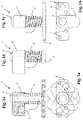
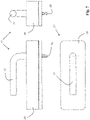
- figure 1 shows in various detailed representations a locking device 1 of a locking system for locking a tilting and/or pivoting window sash with double glazing 18 in a ventilation position.
- the lock has a magnet 2 which is arranged on a bolt 3 .
- the arrester 1 has a bolt 5 connected to a fastening element 4, at the free end of which a limiting element 6, namely a collar, is arranged.
- the bolt 3 has a bore through which the bolt 5 runs.
- the bolt 3 can be rotated about the axis of longitudinal extension of the bolt 5 and thus transferred to different positions, which in Figure 1a is shown.
- Figure 1b shows the locking device in a top view.
- the fastening element 4 is designed as a plate with a plurality of fastening bores 7 which can be screwed onto the frame; in such a way that the bolt protrudes perpendicularly from the frame.
- the Figures 1c and 1d show the lock in different side views while Figure 1e shows the arrester in cross section.
- the locking device 1 has a helical spring 8 which is arranged concentrically to the bolt 5 and which is supported on the one hand on the fastening element 4 and on the other hand on the bolt 3, whereby the bolt 3 is pressed against the limiting element 6, namely the end collar of the bolt 5.
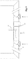
- figure 2 illustrates the functionality of the in figure 1 shown arrester.
- Figure 2a shows the arrester 1 in a release position, in which the bolt 3 is pivoted out of the pivoting range of a window sash 9, so that the bolt 3 is inoperative when the window sash 9 is opened and closed.
- the window sash 9 cannot go further than the ventilation position, which is in Figure 2b is shown to be opened.
- a counter-element 10 is attached to the window sash 9 and interacts with the magnet 2 in the locked position. This prevents the window sash from moving from the ventilation position to the closed position unintentionally, for example due to a draft. Rather, the window sash 9 is held in the locked position by the magnetic force of the magnet 2 .
- the spring 8 cushions a movement of the bolt 3 .
- the magnetic force can be designed so large that the connection of the magnet 2 to the counter-element 10 also remains when the window sash is moved to the closed position, for example manually.
- the magnet 2 and the counter-element 10 then remain in contact until the bolt 3 is in the release position ( Figure 2a ) is pivoted.
- the closed position, in which the magnet 2 is still in contact with the counter-element 10, is in Figure 2c shown.
- the spring force it is also possible to design the spring force to be somewhat higher than the magnetic force. In this case, the bolt 3 is automatically separated from the counter-element 10 when the window sash 9 is closed manually.
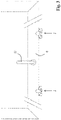
- figure 3 shows a detail of a window with a sash 9, which by means of two arresters 1, as shown in the figures 1 and 2 are described, is held in the ventilation position.
- the window also has a rotary handle 11 for transferring a locking fitting of the window from a locked position to an unlocked position or from an unlocked position to a locked position.
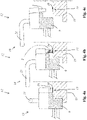
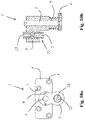
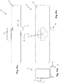
- figure 4 shows a swivel drive 12 which does not belong to the invention and which has a first locking component 13 and a second locking component 14 .
- the second locking component 14 is designed as a counter-element 10 in order to interact with a magnet 2 of the first locking component 13 .
- the first locking component 13 is attached to a window sash 9, while the counter-element 10 is attached to a window frame 15 is attached.
- the first locking component 13 has a movable plunger 16 .
- the plunger 16 Triggered by a rotation of an operating lever 21, the plunger 16 can be moved between a retracted position and an extended position, in particular by a motor.
- the plunger 16 In the closed window position, the in Figure 4a is shown, the plunger 16 is in the retracted position. If the plunger 16 is extended, it pushes itself against the window frame 15 and thus presses the window sash 9 into the ventilation position, which in Figure 4b is shown.
- the window sash 9 is secured against further opening and held in the ventilation position by the magnetic force between the magnet 2 and the counter-element 10 . By overcoming the magnetic force of the magnet 2, the window sash 9 can be opened further, manually or by motor, which in Figure 4c is shown.
- Figures 5a and 5b show the in figure 4 shown swivel drive 12 in different side views, while Figure 5c shows the part-turn actuator in a plan view.
- figure 6 shows a detail of a window with a window sash 9, which is connected to two of the figure 1 shown arrester 1 and additionally with the in figure 4 illustrated swivel drive 12 is equipped in the ventilation position.
- the fasteners 1 do not need to have a magnet.
- Transferring a window sash 9 from a closed position to a ventilation position presupposes that an existing locking fitting has been transferred from its locking position to an unlocking position. This can be done manually, for example by operating a rotary handle 11 .
- an actuating device 17 such as that shown in 7 shown in different views, which one (in 7 drive motor, not shown) and additionally (for manual operation and/or emergency operation) has a turning handle 11 .
- the actuating drive motor can advantageously be arranged in a housing 19 of the actuating device 17 .
- the locking fitting of a window can be operated via a square pin 20 in order to move the locking fitting from a locking position into a Unlocked position or to convert from an unlocked position into a locked position.
- this can be done in such a way that when the locking fitting is transferred from a locking position to an unlocking position, the rotary handle 11 is not moved, so that the position of the rotary handle does not indicate from the outside that the window is unlocked.
- figure 8 shows in different views a combination of the in figure 7 described actuating device 17 with the in figure 4 described swivel drive 12, which includes a plunger 16.
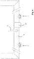
- figure 9 shows a detail of a window with a window sash 9, which is connected to two of the figure 1 shown arresters 1 and with the in figure 4 illustrated swivel drive 12 and with the in figure 7 illustrated actuating device 17 is equipped.
- the window has a special ventilation system in which all processes that are required for ventilation, in particular for regular ventilation, can take place automatically.
- provision can advantageously be made for this window to be unlocked at regular time intervals for predetermined and/or specifiable ventilation intervals and transferred to a ventilation position, with the window being automatically closed and locked again after each ventilation.
- the locking fitting of the window is first switched into an unlocking position by means of an actuating device 17, in particular prompted by a control device.
- the window is then moved into the ventilation position with the help of the swivel drive 12, where the window sash 9 strikes the bolt 3 of the locking device 1.
- the window sash 9 is returned to the closed position with the rotary drive 12, namely by retracting the plunger 16, and is locked there by means of the actuating device 17.
- figure 10 shows another embodiment of a detent, which essentially corresponds to the detent 1, which is in the figures 1 and 2 is shown.
- the part of the bolt 3 that can be moved into the pivoting range of a window sash has a stop element 22 whose axial position, namely its distance from a window frame, is adjustable.
- the stop element 22 carries a magnet 2.
- FIGS. 11a to 11c show different views of a ventilation system 24 which, in a common housing 25, contains both an actuating device 17 for locking and unlocking a locking fitting and a swivel drive 12 with a drive motor 35 which has a plunger 16.
- the actuating device 17 makes it possible to turn a square pin 20 either by motor or with the aid of a rotary handle 11 and thus to operate a locking fitting.
- a window sash, to which the ventilation system 24 is attached, can be moved into a ventilation position with the aid of the drive motor 35 .
- the plunger 16, at the free end of which a magnet 2 is arranged, is supported on a window frame.
- the ventilation system is attached to the casement frame of a window casement.
- a counter-element 10 (not shown in this figure) for the magnet 2 is fastened to the frame of the window.
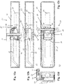
- Figures 12a to 12d show the ventilation system 24 in different representations.
- Figure 12a shows the ventilation system 24 in a sectional view.
- the ventilation system 24 has an electric actuating drive motor 26, at the output of which a pinion 27 is arranged.
- the pinion 27 meshes with a ring gear 28 which is connected to the square pin 20 in a torque-proof manner.
- the ventilation system 24 is screwed onto the casement frame of a window casement in such a way that the square pin 20 engages in the corresponding receptacle of the locking fitting.
- the square pin 20 can also be operated manually, namely with the aid of a turning handle 11 . This is the case, for example, in an emergency and/or when the power supply to the actuating drive motor 26 has failed (for example when the batteries are empty).
- the ventilation system 24 has a plunger 16, at the free end of which a stop element 22 with a magnet 2 is arranged.
- the position of the stop element 22 can be adjusted relative to the remaining components of the plunger 16 with the help of an adjusting screw 23 here. This in particular in order to be able to adjust the width of the opening gap in the ventilation position.
- the ram 16 can be moved, driven by a motor, between a retracted position and an extended position.
- the ram 16 is arranged laterally on a holding bridge 30 which is fastened to two guide rockers 31 .
- the guide wings 31 are each rotatably mounted with pivot bearings 32. Due to the great length of the guide rockers 31 compared to the adjustment path of the ram 16, the movement of the ram 16 together with its holding bridge 30 is almost linear.
- the plunger 16 can also be attached to the retaining bridge 30 in an alternative position 33, depending on whether the ventilation system 24 is to be used on a window sash 9 hinged on the left or on a window sash 9 hinged on the right.
- the swivel drive has a drive motor 35 with which the plunger 16 can be moved. At the output of the drive motor 35 there is an eccentric 36 which engages with a bolt 38 in a slot guide 37 connected to the holding bridge 30 .
- Figure 13a shows the two guide rockers 31, which are pivotally mounted with the aid of pivot bearings 32.
- a retaining bridge 30 is arranged at the end of the guide rocker 31 into which a retaining pin 29 of the plunger 16 can be inserted on both sides, depending on whether the ventilation system 24 is to be used on a window hinged on the right or on a window hinged on the left.
- the longitudinal guide 37 is located on the retaining bridge 30 and is engaged by the bolt 38 of the eccentric 36 which is coupled to the output of the drive motor 35 .
- Figure 13b shows in particular the stabilizer links 34, which are connected to one another in a rotationally fixed manner and engage in fork-shaped receptacles 39 on the retaining bridge 30.
- the stabilizer rockers 34 serve to prevent the holding bridge 30 from tilting.
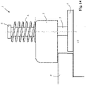
- FIG 14 shows a locking device 1 for a locking system which, in addition to the locking device 1, has a swivel drive.
- the arrester 1 has the task of preventing the window sash 9 from being opened further beyond the ventilation position.
- this special arrester 1 has the task of moving the window sash 9 from the ventilation position back to the closed position as soon as the plunger 16 of the rotary drive 35 is retracted.
- neither the swivel drive 35 nor the locking device 1 needs to have a magnet.
- the arrester can have a bolt 5 provided with a fastening element 4 , which is designed and intended to be fastened to a window frame 15 by means of the fastening element 4 , the bolt 5 carrying a movably mounted bolt 3 .
- the bolt 3 is mounted on the bolt 5 so that it can move axially and is held in place by a spring 8 in Direction pressed on the fastener 4.
- the window sash 9 can be opened with the help of the drive motor 35 (in 14 not shown) against the force of the spring 8 up to the ventilation position in which the latch strikes a limiting element 6 and prevents further opening.
- the plunger 16 of the drive motor 35 is pressed against the window frame 15 . If the plunger 16 of the drive motor 35 is retracted again, the spring-loaded latch 3 pushes the sash 9 back into the closed position.
Landscapes
- Power-Operated Mechanisms For Wings (AREA)
- Specific Sealing Or Ventilating Devices For Doors And Windows (AREA)
- Wing Frames And Configurations (AREA)
- Window Of Vehicle (AREA)
Claims (14)
- Entraînement en pivotement (12) pour transférer un battant de fenêtre (9) basculant et/ou pivotant dans une position d'aération, l'entraînement en pivotement (12) étant configuré et adapté pour être fixé à un battant de fenêtre (9) et l'entraînement en pivotement (12) présente un poussoir (16) pouvant être déplacé entre une position rétractée et une position déployée, qui est configuré et adapté pour s'appuyer par son extrémité libre sur un cadre dormant (15) lors du transfert du poussoir (16) de la position rétractée à la position déployée, caractérisé en ce que le poussoir (16) présente un aimant (2) ou en ce que l'entraînement en pivotement (12) présente un contre-élément (10) à disposer sur le cadre dormant (15), qui présente un aimant (2), et le poussoir (16) est fabriqué en un matériau qui peut coopérer avec l'aimant (2), le poussoir présentant un élément de butée (22) dont la position est réglable par rapport à un autre composant du poussoir (16).
- Entraînement en pivotement (12) selon la revendication 1, caractérisé en ce quea. l'entraînement en pivotement (12) présente un moteur d'entraînement électrique (35) et une transmission montée en aval du moteur d'entraînement (35), ou en ce queb. l'entraînement en pivotement (12) présente un moteur d'entraînement électrique (35) et une transmission autobloquante, montée en aval du moteur d'entraînement (35), ou en ce quec. l'entraînement en pivotement (12) présente un moteur d'entraînement électrique (35) et une transmission autobloquante exclusivement dans les positions finales, montée en aval du moteur d'entraînement (35).
- Entraînement en pivotement (12) selon la revendication 1 ou 2, caractérisé en ce quea. l'entraînement en pivotement (12) est configuré pour être commandé au moyen d'une commande à distance, notamment sans fil, ou en ce queb. l'entraînement en pivotement (12) est configuré pour être commandé à distance, notamment sans fil, ou en ce quec. l'entraînement en pivotement (12) présente une commande à distance, notamment sans fil.
- Système de blocage présentant un entraînement en pivotement (12) selon l'une quelconque des revendications 1 à 3 et un dispositif de blocage (1), quia. peut être transféré dans une position d'immobilisation, dans laquelle il empêche une ouverture du battant de fenêtre (9) au-delà de la position d'ouverture, ou quib. peut être commuté entre une position d'immobilisation, dans laquelle il maintient un battant de fenêtre (9) dans une position d'aération, et une position de libération, dans laquelle le battant de fenêtre (9) est libéré.
- Système de blocage selon la revendication 4, caractérisé en ce quea. le dispositif de blocage (1) présente un verrou (3) monté à rotation sur un boulon (5), ou en ce queb. le dispositif de blocage (1) présente un verrou (3) monté à rotation autour d'un axe longitudinal de boulon sur un boulon (5), ou en ce quec. le dispositif de blocage (1) présente un verrou (3) monté à rotation sur un boulon (5), qui peut être tourné au choix dans une position d'immobilisation ou une position de libération, ou en ce qued. le dispositif de blocage (1) présente un boulon (5) pourvu d'un élément de fixation (4), qui est configuré et adapté pour être fixé à un cadre dormant (15) au moyen de l'élément de fixation (4), et qui porte un verrou (3) monté mobile par rapport au boulon (5), ou en ce quee. le dispositif de blocage (1) présente un boulon (5) pourvu d'un élément de fixation (4), qui est configuré et adapté pour être fixé à un cadre dormant (15) au moyen de l'élément de fixation (4), et qui porte un verrou (3) monté mobile par rapport au boulon (5), le verrou (3) étant monté mobile axialement sur le boulon (5), ou en ce quef. le dispositif de blocage (1) comprend un boulon (5) pourvu d'un élément de fixation (4), qui est configuré et adapté pour être fixé à un cadre dormant (15) au moyen de l'élément de fixation (4), et qui porte un verrou (3) monté mobile par rapport au boulon (5), le verrou (3) étant monté mobile axialement sur le boulon (5), le verrou (3) étant poussé en direction de l'élément de fixation (4) au moyen d'un ressort (8), ou en ce queg. le dispositif de blocage (1) présente un verrou (3) monté à rotation sur un boulon (5), comprenant un aimant (2).
- Système de blocage selon la revendication 5, caractérisé en ce quea. le boulon (5) est configuré et adapté pour être fixé à un cadre dormant (15) de telle sorte que le verrou (3) peut être déplacé, notamment tourné, dans la zone de pivotement d'un battant de fenêtre (9) afin d'immobiliser le battant de fenêtre (9) dans une position d'aération, ou en ce queb. le boulon (5) est configuré et adapté pour être fixé à un cadre dormant (15) de telle sorte que le verrou (3) soit peut être déplacé, notamment tourné, dans la zone de pivotement d'un battant de fenêtre (9) afin d'immobiliser le battant de fenêtre (9) dans une position d'aération, soit peut être déplacé, notamment tourné, hors de la zone de pivotement d'un battant de fenêtre (9) afin de libérer le battant de fenêtre (9).
- Système de blocage selon la revendication 5 ou 6, caractérisé en ce quea. le verrou (3) déplacé dans la zone de pivotement d'un battant de fenêtre (9) sert de butée pour le battant de fenêtre (9), ou en ce queb. le verrou (3) déplacé dans la zone de pivotement d'un battant de fenêtre (9) sert de butée pour le battant de fenêtre (9), le battant de fenêtre (9) pouvant être ouvert d'une fente d'ouverture prédéterminée ou réglable, notamment dans la plage allant de 8 mm à 12 mm ou dans la plage allant de 8 mm à 16 mm, jusqu'à ce qu'il vienne en butée contre le verrou (3), ou en ce quec. le verrou (3) déplacé dans la zone de pivotement d'un battant de fenêtre (9) sert de butée pour le battant de fenêtre (9), le battant de fenêtre (9) pouvant être ouvert d'une fente d'ouverture prédéterminée ou réglable, notamment dans la plage allant de 8 mm à 12 mm ou dans la plage allant de 8 mm à 16 mm, jusqu'à ce qu'il vienne en butée contre le verrou (3) et soit ensuite maintenu dans cette position d'aération par l'aimant (2), ou en ce qued. la partie du verrou (3) pouvant être déplacée dans la zone de pivotement d'un battant de fenêtre (9) présente un élément de butée (22), dont la position, notamment la distance par rapport à un cadre dormant (15), est réglable.
- Système d'aération, qui présente un entraînement en pivotement (12) selon l'une quelconque des revendications 1 à 3 ou un système de blocage selon l'une quelconque des revendications 4 à 7 et qui présente un dispositif d'actionnement (17) pour actionner la ferrure de verrouillage d'une fenêtre.
- Système d'aération selon la revendication 8, caractérisé en ce quea. le dispositif d'actionnement (17) présente un moteur d'entraînement d'actionnement électrique (26) pour transférer une ferrure de verrouillage d'une position de verrouillage à une position de déverrouillage ou d'une position de déverrouillage à une position de verrouillage, ou en ce queb. le dispositif d'actionnement (17) présente un moteur d'entraînement d'actionnement (26) alimenté par batterie pour transférer une ferrure de verrouillage d'une position de verrouillage à une position de déverrouillage ou d'une position de déverrouillage à une position de verrouillage, ou en ce quec. le dispositif d'actionnement (17) présente un moteur d'entraînement d'actionnement électrique (26) et une transmission d'actionnement montée en aval du moteur d'entraînement d'actionnement (26) pour transférer une ferrure de verrouillage d'une position de verrouillage à une position de déverrouillage ou d'une position de déverrouillage à une position de verrouillage, ou en ce qued. le dispositif d'actionnement (17) présente un moteur d'entraînement d'actionnement électrique (26) et une transmission d'actionnement non autobloquante, montée en aval du moteur d'entraînement d'actionnement (26), ou en ce quee. le dispositif d'actionnement (17) présente une manette, notamment une poignée tournante (11), pour un fonctionnement manuel, ou en ce quef. le dispositif d'actionnement (17) présente une manette, notamment une poignée tournante (11), pour un fonctionnement manuel, qui peut être transférée manuellement, au choix, dans une première position qui est associée à une position de verrouillage du dispositif d'actionnement (17) ou dans une deuxième position qui est associée à une position de déverrouillage du dispositif d'actionnement (17), la manette restant dans sa première position lorsque le dispositif d'actionnement (17) est commuté de la position de verrouillage à la position de déverrouillage au moyen du moteur d'entraînement d'actionnement (26), ou en ce queg. le dispositif d'actionnement (17) est configuré pour être commandé au moyen d'une commande à distance, notamment sans fil, ou en ce queh. le dispositif d'actionnement (17) est configuré pour être commandé à distance, notamment sans fil, ou en ce quei. le dispositif de blocage (1) présente une commande à distance, notamment sans fil, pour commander le dispositif d'actionnement, ou en ce quej. le dispositif d'actionnement (17) et l'entraînement en pivotement (12) présentent un boîtier commun (25) et/ou sont exploités avec le même moteur d'entraînement (35).
- Système d'aération selon la revendication 8 ou 9, caractérisé en ce quea. le dispositif d'actionnement (17) et/ou le dispositif de blocage (1) présentent un capteur électronique pour déterminer la position du dispositif d'actionnement (17) et/ou du dispositif de blocage (1), ou en ce queb. le dispositif d'actionnement (17) et/ou le dispositif de blocage (1) sont configurés pour détecter des vibrations et/ou des manipulations et pour émettre un signal d'alarme, ou en ce quec. le dispositif d'actionnement (17) et/ou le dispositif de blocage (1) présentent un capteur électronique pour déterminer la position du dispositif d'actionnement (17) et/ou du dispositif de blocage (1) et en ce que le dispositif d'actionnement (17) et le dispositif de blocage (1) sont configurés pour détecter des vibrations et/ou des manipulations et pour émettre un signal d'alarme.
- Ensemble comprenant un entraînement en pivotement (12) selon l'une quelconque des revendications 1 à 3 ou un système d'aération selon l'une quelconque des revendications 8 à 10, caractérisé par un dispositif de commande pour la commande, notamment automatique, de l'entraînement en pivotement (12) et/ou pour la commande du dispositif d'actionnement (17) du système d'aération.
- Ensemble selon la revendication 11, caractérisé en ce quea. le dispositif de commande transfère un battant de fenêtre (9) d'une position fermée à une position d'aération à des intervalles de temps prédéterminés ou prédéterminables, respectivement pour une période d'aération prédéterminée ou prédéterminable, ou en ce queb. le dispositif de commande présente un capteur pour mesurer un paramètre de l'air ambiant, notamment l'humidité de l'air, et en ce que le dispositif de commande transfère un battant de fenêtre (9) d'une position fermée à une position d'aération lorsqu'un paramètre de l'air ambiant mesuré dépasse une valeur d'ouverture prédéterminée ou prédéterminable, ou en ce quec. le dispositif de commande présente un capteur pour mesurer un paramètre de l'air ambiant, notamment l'humidité de l'air, et en ce que le dispositif de commande transfère un battant de fenêtre (9) d'une position d'aération à une position fermée lorsqu'un paramètre de l'air ambiant mesuré passe en dessous d'une valeur d'ouverture prédéterminée ou prédéterminable, ou en ce qued. le capteur est configuré et adapté pour être agencé séparément dans l'espace de l'entraînement en pivotement (12) et/ou du dispositif d'actionnement (17) .
- Système de maison intelligente comprenant un entraînement en pivotement (12) selon l'une quelconque des revendications 1 à 3 ou un système de blocage selon l'une quelconque des revendications 4 à 7 ou un système d'aération selon l'une quelconque des revendications 8 à 10 ou un ensemble selon la revendication 11 ou 12.
- Fenêtre avec un entraînement en pivotement (12) selon l'une quelconque des revendications 1 à 3 ou avec un système de blocage selon l'une quelconque des revendications 4 à 7 ou avec un système d'aération selon l'une quelconque des revendications 8 à 10.
Applications Claiming Priority (1)
| Application Number | Priority Date | Filing Date | Title |
|---|---|---|---|
| DE102015104047.6A DE102015104047A1 (de) | 2015-03-18 | 2015-03-18 | Feststeller zum Arretieren eines kipp- und/oder schwenkbaren Fensterflügels |
Publications (3)
| Publication Number | Publication Date |
|---|---|
| EP3073040A2 EP3073040A2 (fr) | 2016-09-28 |
| EP3073040A3 EP3073040A3 (fr) | 2016-12-28 |
| EP3073040B1 true EP3073040B1 (fr) | 2022-12-21 |
Family
ID=55696914
Family Applications (1)
| Application Number | Title | Priority Date | Filing Date |
|---|---|---|---|
| EP16161050.6A Active EP3073040B1 (fr) | 2015-03-18 | 2016-03-18 | Verrouillage pour arreter un vantail de fenetre pivotant et/ou basculant |
Country Status (2)
| Country | Link |
|---|---|
| EP (1) | EP3073040B1 (fr) |
| DE (2) | DE102015104047A1 (fr) |
Families Citing this family (9)
| Publication number | Priority date | Publication date | Assignee | Title |
|---|---|---|---|---|
| US9995066B1 (en) * | 2017-01-13 | 2018-06-12 | Inteva Products, Llc | Vehicle door opening mechanism |
| LU100181B1 (de) * | 2017-04-28 | 2018-10-30 | Schellenberg Alfred Gmbh | Vorrichtung zum Begrenzen des maximalen Schwenk- oder Kippwinkels eines Fenster- und Türflügels |
| LU100183B1 (de) * | 2017-04-28 | 2018-10-30 | Schellenberg Alfred Gmbh | Automatisches Lüftungssystem |
| DE102017109242A1 (de) | 2017-04-28 | 2018-10-31 | Alfred Schellenberg Gmbh | Automatisches Lüftungssystem |
| US11274477B2 (en) | 2017-06-05 | 2022-03-15 | Magna Closures Inc. | Integrated door presentment mechanism for a latch |
| LU100368B1 (de) | 2017-08-15 | 2019-03-19 | Schellenberg Alfred Gmbh | Motorisierter Schwenkantrieb für einen Fensterflügel und Verfahren zum Befestigen eines Schwenkantriebs an einem Fensterflügel |
| FR3072993B1 (fr) * | 2017-11-02 | 2023-01-06 | U Shin France | Systeme entrebaillement pour ouvrant de vehicule automobile |
| CN110005295A (zh) * | 2019-05-20 | 2019-07-12 | 华人运通(江苏)技术有限公司 | 车门的助推装置和其控制方法以及具有其的车门、车辆 |
| FR3118086B1 (fr) * | 2020-12-18 | 2023-10-27 | Commissariat A L’Energie Atomique Et Aux Energies Alternatives | Système d’ouverture automatisée d’un ouvrant |
Citations (2)
| Publication number | Priority date | Publication date | Assignee | Title |
|---|---|---|---|---|
| DE7416373U (de) * | 1974-10-10 | Rakoczy M | Arretierungsriegel für teilweise zu öffnende Kippfenster | |
| DE4115054C2 (de) * | 1990-05-10 | 2000-06-21 | Heinrich Schlueter | Einrichtung zur Belüftung von Fenster oder Türen mit beweglichem Flügel aufweisenden Räumen in Gebäuden |
Family Cites Families (10)
| Publication number | Priority date | Publication date | Assignee | Title |
|---|---|---|---|---|
| DE1764109U (de) | 1957-11-05 | 1958-03-27 | Willy Junker | Feststellvorrichtung fuer kipp- und drehfluegelfenster. |
| DE1861427U (de) | 1962-07-04 | 1962-10-31 | Gretsch Unitas Gmbh | Vorrichtung zur einstellung kleiner lueftungsstellen an insbesondere schwing- oder wendefenstern. |
| US4042265A (en) * | 1976-10-27 | 1977-08-16 | Chezem Jimmie A | Wedge-type limit stop for outward opening door |
| DE3131181A1 (de) | 1981-08-06 | 1983-02-24 | Gretsch-Unitas Gmbh Baubeschlagfabrik, 7257 Ditzingen | Beschlag fuer einen wenigstens drehbaren und/oder kippbaren fluegel eines fensters, einer tuer od.dgl. |
| DE8427019U1 (de) | 1984-09-13 | 1984-12-13 | Emerschitz, Theodor, 7000 Stuttgart | Feststeller fuer fensterfluegel |
| DE8627840U1 (de) * | 1986-10-18 | 1986-12-04 | Kalle, Gerhard, 4630 Bochum | Aggregat zur mehrstufigen Festlegung dreh oder kippbarer Flügelrahmen von Fenstern und Balkontüren, in einhändiger Bedienungsweise selbsttätig einrastbar |
| DE3915569A1 (de) * | 1989-05-12 | 1990-11-15 | Winkhaus Fa August | Fenstersystem fuer ein gebaeude |
| DE9309551U1 (de) * | 1993-06-26 | 1993-09-09 | GEZE GmbH, 71229 Leonberg | Antrieb für einen Flügel mit einem Motor mit abtriebsseitiger Motorstange |
| DE102009027313A1 (de) * | 2009-06-30 | 2010-10-07 | Geze Gmbh | Antrieb für einen Flügel eines Fensters |
| DE102013007191B3 (de) * | 2013-04-25 | 2014-05-22 | Thorsten Russ | Tür- oder Fenstersicherung sowie Türe oder Fenster mit einer Tür- oder Fenstersicherung |
-
2015
- 2015-03-18 DE DE102015104047.6A patent/DE102015104047A1/de not_active Ceased
-
2016
- 2016-03-18 EP EP16161050.6A patent/EP3073040B1/fr active Active
- 2016-03-18 DE DE202016009122.1U patent/DE202016009122U1/de not_active Expired - Lifetime
Patent Citations (2)
| Publication number | Priority date | Publication date | Assignee | Title |
|---|---|---|---|---|
| DE7416373U (de) * | 1974-10-10 | Rakoczy M | Arretierungsriegel für teilweise zu öffnende Kippfenster | |
| DE4115054C2 (de) * | 1990-05-10 | 2000-06-21 | Heinrich Schlueter | Einrichtung zur Belüftung von Fenster oder Türen mit beweglichem Flügel aufweisenden Räumen in Gebäuden |
Also Published As
| Publication number | Publication date |
|---|---|
| DE202016009122U1 (de) | 2022-08-22 |
| EP3073040A3 (fr) | 2016-12-28 |
| EP3073040A2 (fr) | 2016-09-28 |
| DE102015104047A1 (de) | 2016-09-22 |
Similar Documents
| Publication | Publication Date | Title |
|---|---|---|
| DE202016009122U1 (de) | Schwenkantrieb zum Überführen eines kipp- und/oder schwenkbaren Fensterflügels in eine Lüftungsstellung | |
| EP1832700B1 (fr) | Système de verrouillage pour une porte | |
| EP2459824B1 (fr) | Dispositif de fermeture de porte | |
| DE2611359A1 (de) | Treibstangenverschluss, insbesondere fuer zweifluegelige feuerschutztueren | |
| EP2594713B1 (fr) | Ouverture de porte | |
| EP1292747A1 (fr) | Serrure a verrouillage automatique et systeme de fermeture comportant une telle serrure | |
| EP4386158B1 (fr) | Ouvre-porte | |
| WO2007082514A1 (fr) | Porte, en particulier porte sectionnelle, et dispositif d'entraînement de porte | |
| DE20203565U1 (de) | Schließvorrichtung | |
| EP3511497A1 (fr) | Ferrure de tige d'entraînement pour un élément de fermeture de bâtiment, élément de fermeture de bâtiment correspondant ainsi que procédé de fonctionnement d'une ferrure de tige d'entraînement et procédé de montage d'une ferrure de tige d'entraînement | |
| EP3765688B1 (fr) | Ensemble ferrure pour un châssis de battant d'une fenêtre, fenêtre correspondante, procédé pour faire fonctionner un ensemble ferrure, procédé pour monter un ensemble ferrure et dispositif capteur | |
| EP3034719A1 (fr) | Dispositif d'actionnement d'un mecanisme de verrouillage d'une porte ou d'une fenetre | |
| EP2385196B1 (fr) | Serrure | |
| EP3245371B1 (fr) | Dispositif de sécurité pour sécuriser une porte dans les voies d'évacuation et de sauvetage | |
| EP2199501B1 (fr) | Bâtiment anti-intrusion | |
| WO2013113854A1 (fr) | Ouvre-porte et porte munie d'un ouvre-porte | |
| DE102004018066A1 (de) | Drehkippfenster | |
| DE29619007U1 (de) | Verriegelungsvorrichtung | |
| EP3219887A1 (fr) | Barre de poussée | |
| DE10106674A1 (de) | Verriegelungsvorrichtung für ein Dreh-oder Schiebetor | |
| DE102015104818A1 (de) | Verfahren zum Betreiben eines Türantriebs, Türantriebssteuerung, Türantrieb und Drehflügeltür | |
| EP3655601B1 (fr) | Serrure | |
| EP2642051B1 (fr) | Verrou relâché lors de la fermeture d'une porte | |
| EP4400677B1 (fr) | Serrure, notamment pour portes, avec un pêne pivotant verrouillable | |
| DE102015104825A1 (de) | Verfahren zum Betreiben eines Türantriebs, Türantriebssteuerung, Türantrieb und Drehflügeltür |
Legal Events
| Date | Code | Title | Description |
|---|---|---|---|
| PUAI | Public reference made under article 153(3) epc to a published international application that has entered the european phase |
Free format text: ORIGINAL CODE: 0009012 |
|
| AK | Designated contracting states |
Kind code of ref document: A2 Designated state(s): AL AT BE BG CH CY CZ DE DK EE ES FI FR GB GR HR HU IE IS IT LI LT LU LV MC MK MT NL NO PL PT RO RS SE SI SK SM TR |
|
| AX | Request for extension of the european patent |
Extension state: BA ME |
|
| PUAL | Search report despatched |
Free format text: ORIGINAL CODE: 0009013 |
|
| AK | Designated contracting states |
Kind code of ref document: A3 Designated state(s): AL AT BE BG CH CY CZ DE DK EE ES FI FR GB GR HR HU IE IS IT LI LT LU LV MC MK MT NL NO PL PT RO RS SE SI SK SM TR |
|
| AX | Request for extension of the european patent |
Extension state: BA ME |
|
| RIC1 | Information provided on ipc code assigned before grant |
Ipc: E05F 15/63 20150101ALI20161118BHEP Ipc: E05F 15/616 20150101AFI20161118BHEP |
|
| STAA | Information on the status of an ep patent application or granted ep patent |
Free format text: STATUS: REQUEST FOR EXAMINATION WAS MADE |
|
| 17P | Request for examination filed |
Effective date: 20170628 |
|
| RBV | Designated contracting states (corrected) |
Designated state(s): AL AT BE BG CH CY CZ DE DK EE ES FI FR GB GR HR HU IE IS IT LI LT LU LV MC MK MT NL NO PL PT RO RS SE SI SK SM TR |
|
| RAP1 | Party data changed (applicant data changed or rights of an application transferred) |
Owner name: ALFRED SCHELLENBERG GMBH |
|
| STAA | Information on the status of an ep patent application or granted ep patent |
Free format text: STATUS: EXAMINATION IS IN PROGRESS |
|
| 17Q | First examination report despatched |
Effective date: 20180406 |
|
| GRAP | Despatch of communication of intention to grant a patent |
Free format text: ORIGINAL CODE: EPIDOSNIGR1 |
|
| STAA | Information on the status of an ep patent application or granted ep patent |
Free format text: STATUS: GRANT OF PATENT IS INTENDED |
|
| INTG | Intention to grant announced |
Effective date: 20220209 |
|
| GRAJ | Information related to disapproval of communication of intention to grant by the applicant or resumption of examination proceedings by the epo deleted |
Free format text: ORIGINAL CODE: EPIDOSDIGR1 |
|
| STAA | Information on the status of an ep patent application or granted ep patent |
Free format text: STATUS: EXAMINATION IS IN PROGRESS |
|
| INTC | Intention to grant announced (deleted) | ||
| GRAS | Grant fee paid |
Free format text: ORIGINAL CODE: EPIDOSNIGR3 |
|
| STAA | Information on the status of an ep patent application or granted ep patent |
Free format text: STATUS: GRANT OF PATENT IS INTENDED |
|
| GRAP | Despatch of communication of intention to grant a patent |
Free format text: ORIGINAL CODE: EPIDOSNIGR1 |
|
| INTG | Intention to grant announced |
Effective date: 20220802 |
|
| GRAA | (expected) grant |
Free format text: ORIGINAL CODE: 0009210 |
|
| STAA | Information on the status of an ep patent application or granted ep patent |
Free format text: STATUS: THE PATENT HAS BEEN GRANTED |
|
| AK | Designated contracting states |
Kind code of ref document: B1 Designated state(s): AL AT BE BG CH CY CZ DE DK EE ES FI FR GB GR HR HU IE IS IT LI LT LU LV MC MK MT NL NO PL PT RO RS SE SI SK SM TR |
|
| REG | Reference to a national code |
Ref country code: GB Ref legal event code: FG4D Free format text: NOT ENGLISH |
|
| REG | Reference to a national code |
Ref country code: CH Ref legal event code: EP |
|
| REG | Reference to a national code |
Ref country code: DE Ref legal event code: R096 Ref document number: 502016015484 Country of ref document: DE |
|
| REG | Reference to a national code |
Ref country code: AT Ref legal event code: REF Ref document number: 1539151 Country of ref document: AT Kind code of ref document: T Effective date: 20230115 |
|
| REG | Reference to a national code |
Ref country code: IE Ref legal event code: FG4D Free format text: LANGUAGE OF EP DOCUMENT: GERMAN |
|
| REG | Reference to a national code |
Ref country code: LT Ref legal event code: MG9D |
|
| REG | Reference to a national code |
Ref country code: NL Ref legal event code: MP Effective date: 20221221 |
|
| PG25 | Lapsed in a contracting state [announced via postgrant information from national office to epo] |
Ref country code: SE Free format text: LAPSE BECAUSE OF FAILURE TO SUBMIT A TRANSLATION OF THE DESCRIPTION OR TO PAY THE FEE WITHIN THE PRESCRIBED TIME-LIMIT Effective date: 20221221 Ref country code: NO Free format text: LAPSE BECAUSE OF FAILURE TO SUBMIT A TRANSLATION OF THE DESCRIPTION OR TO PAY THE FEE WITHIN THE PRESCRIBED TIME-LIMIT Effective date: 20230321 Ref country code: LT Free format text: LAPSE BECAUSE OF FAILURE TO SUBMIT A TRANSLATION OF THE DESCRIPTION OR TO PAY THE FEE WITHIN THE PRESCRIBED TIME-LIMIT Effective date: 20221221 Ref country code: FI Free format text: LAPSE BECAUSE OF FAILURE TO SUBMIT A TRANSLATION OF THE DESCRIPTION OR TO PAY THE FEE WITHIN THE PRESCRIBED TIME-LIMIT Effective date: 20221221 |
|
| PGFP | Annual fee paid to national office [announced via postgrant information from national office to epo] |
Ref country code: AT Payment date: 20230322 Year of fee payment: 8 |
|
| PG25 | Lapsed in a contracting state [announced via postgrant information from national office to epo] |
Ref country code: RS Free format text: LAPSE BECAUSE OF FAILURE TO SUBMIT A TRANSLATION OF THE DESCRIPTION OR TO PAY THE FEE WITHIN THE PRESCRIBED TIME-LIMIT Effective date: 20221221 Ref country code: LV Free format text: LAPSE BECAUSE OF FAILURE TO SUBMIT A TRANSLATION OF THE DESCRIPTION OR TO PAY THE FEE WITHIN THE PRESCRIBED TIME-LIMIT Effective date: 20221221 Ref country code: HR Free format text: LAPSE BECAUSE OF FAILURE TO SUBMIT A TRANSLATION OF THE DESCRIPTION OR TO PAY THE FEE WITHIN THE PRESCRIBED TIME-LIMIT Effective date: 20221221 Ref country code: GR Free format text: LAPSE BECAUSE OF FAILURE TO SUBMIT A TRANSLATION OF THE DESCRIPTION OR TO PAY THE FEE WITHIN THE PRESCRIBED TIME-LIMIT Effective date: 20230322 |
|
| PGFP | Annual fee paid to national office [announced via postgrant information from national office to epo] |
Ref country code: DE Payment date: 20230310 Year of fee payment: 8 |
|
| PG25 | Lapsed in a contracting state [announced via postgrant information from national office to epo] |
Ref country code: NL Free format text: LAPSE BECAUSE OF FAILURE TO SUBMIT A TRANSLATION OF THE DESCRIPTION OR TO PAY THE FEE WITHIN THE PRESCRIBED TIME-LIMIT Effective date: 20221221 |
|
| PG25 | Lapsed in a contracting state [announced via postgrant information from national office to epo] |
Ref country code: SM Free format text: LAPSE BECAUSE OF FAILURE TO SUBMIT A TRANSLATION OF THE DESCRIPTION OR TO PAY THE FEE WITHIN THE PRESCRIBED TIME-LIMIT Effective date: 20221221 Ref country code: RO Free format text: LAPSE BECAUSE OF FAILURE TO SUBMIT A TRANSLATION OF THE DESCRIPTION OR TO PAY THE FEE WITHIN THE PRESCRIBED TIME-LIMIT Effective date: 20221221 Ref country code: PT Free format text: LAPSE BECAUSE OF FAILURE TO SUBMIT A TRANSLATION OF THE DESCRIPTION OR TO PAY THE FEE WITHIN THE PRESCRIBED TIME-LIMIT Effective date: 20230421 Ref country code: ES Free format text: LAPSE BECAUSE OF FAILURE TO SUBMIT A TRANSLATION OF THE DESCRIPTION OR TO PAY THE FEE WITHIN THE PRESCRIBED TIME-LIMIT Effective date: 20221221 Ref country code: EE Free format text: LAPSE BECAUSE OF FAILURE TO SUBMIT A TRANSLATION OF THE DESCRIPTION OR TO PAY THE FEE WITHIN THE PRESCRIBED TIME-LIMIT Effective date: 20221221 Ref country code: CZ Free format text: LAPSE BECAUSE OF FAILURE TO SUBMIT A TRANSLATION OF THE DESCRIPTION OR TO PAY THE FEE WITHIN THE PRESCRIBED TIME-LIMIT Effective date: 20221221 |
|
| PG25 | Lapsed in a contracting state [announced via postgrant information from national office to epo] |
Ref country code: SK Free format text: LAPSE BECAUSE OF FAILURE TO SUBMIT A TRANSLATION OF THE DESCRIPTION OR TO PAY THE FEE WITHIN THE PRESCRIBED TIME-LIMIT Effective date: 20221221 Ref country code: PL Free format text: LAPSE BECAUSE OF FAILURE TO SUBMIT A TRANSLATION OF THE DESCRIPTION OR TO PAY THE FEE WITHIN THE PRESCRIBED TIME-LIMIT Effective date: 20221221 Ref country code: IS Free format text: LAPSE BECAUSE OF FAILURE TO SUBMIT A TRANSLATION OF THE DESCRIPTION OR TO PAY THE FEE WITHIN THE PRESCRIBED TIME-LIMIT Effective date: 20230421 Ref country code: AL Free format text: LAPSE BECAUSE OF FAILURE TO SUBMIT A TRANSLATION OF THE DESCRIPTION OR TO PAY THE FEE WITHIN THE PRESCRIBED TIME-LIMIT Effective date: 20221221 |
|
| REG | Reference to a national code |
Ref country code: DE Ref legal event code: R097 Ref document number: 502016015484 Country of ref document: DE |
|
| PLBE | No opposition filed within time limit |
Free format text: ORIGINAL CODE: 0009261 |
|
| STAA | Information on the status of an ep patent application or granted ep patent |
Free format text: STATUS: NO OPPOSITION FILED WITHIN TIME LIMIT |
|
| PG25 | Lapsed in a contracting state [announced via postgrant information from national office to epo] |
Ref country code: MC Free format text: LAPSE BECAUSE OF FAILURE TO SUBMIT A TRANSLATION OF THE DESCRIPTION OR TO PAY THE FEE WITHIN THE PRESCRIBED TIME-LIMIT Effective date: 20221221 Ref country code: DK Free format text: LAPSE BECAUSE OF FAILURE TO SUBMIT A TRANSLATION OF THE DESCRIPTION OR TO PAY THE FEE WITHIN THE PRESCRIBED TIME-LIMIT Effective date: 20221221 |
|
| REG | Reference to a national code |
Ref country code: CH Ref legal event code: PL |
|
| 26N | No opposition filed |
Effective date: 20230922 |
|
| GBPC | Gb: european patent ceased through non-payment of renewal fee |
Effective date: 20230321 |
|
| REG | Reference to a national code |
Ref country code: BE Ref legal event code: MM Effective date: 20230331 |
|
| PG25 | Lapsed in a contracting state [announced via postgrant information from national office to epo] |
Ref country code: LU Free format text: LAPSE BECAUSE OF NON-PAYMENT OF DUE FEES Effective date: 20230318 |
|
| REG | Reference to a national code |
Ref country code: IE Ref legal event code: MM4A |
|
| PG25 | Lapsed in a contracting state [announced via postgrant information from national office to epo] |
Ref country code: GB Free format text: LAPSE BECAUSE OF NON-PAYMENT OF DUE FEES Effective date: 20230321 |
|
| PG25 | Lapsed in a contracting state [announced via postgrant information from national office to epo] |
Ref country code: SI Free format text: LAPSE BECAUSE OF FAILURE TO SUBMIT A TRANSLATION OF THE DESCRIPTION OR TO PAY THE FEE WITHIN THE PRESCRIBED TIME-LIMIT Effective date: 20221221 Ref country code: LI Free format text: LAPSE BECAUSE OF NON-PAYMENT OF DUE FEES Effective date: 20230331 Ref country code: IE Free format text: LAPSE BECAUSE OF NON-PAYMENT OF DUE FEES Effective date: 20230318 Ref country code: GB Free format text: LAPSE BECAUSE OF NON-PAYMENT OF DUE FEES Effective date: 20230321 Ref country code: FR Free format text: LAPSE BECAUSE OF NON-PAYMENT OF DUE FEES Effective date: 20230331 Ref country code: CH Free format text: LAPSE BECAUSE OF NON-PAYMENT OF DUE FEES Effective date: 20230331 |
|
| PG25 | Lapsed in a contracting state [announced via postgrant information from national office to epo] |
Ref country code: BE Free format text: LAPSE BECAUSE OF NON-PAYMENT OF DUE FEES Effective date: 20230331 |
|
| PG25 | Lapsed in a contracting state [announced via postgrant information from national office to epo] |
Ref country code: IT Free format text: LAPSE BECAUSE OF FAILURE TO SUBMIT A TRANSLATION OF THE DESCRIPTION OR TO PAY THE FEE WITHIN THE PRESCRIBED TIME-LIMIT Effective date: 20221221 |
|
| REG | Reference to a national code |
Ref country code: DE Ref legal event code: R119 Ref document number: 502016015484 Country of ref document: DE |
|
| PG25 | Lapsed in a contracting state [announced via postgrant information from national office to epo] |
Ref country code: BG Free format text: LAPSE BECAUSE OF FAILURE TO SUBMIT A TRANSLATION OF THE DESCRIPTION OR TO PAY THE FEE WITHIN THE PRESCRIBED TIME-LIMIT Effective date: 20221221 |
|
| REG | Reference to a national code |
Ref country code: AT Ref legal event code: MM01 Ref document number: 1539151 Country of ref document: AT Kind code of ref document: T Effective date: 20240318 |
|
| PG25 | Lapsed in a contracting state [announced via postgrant information from national office to epo] |
Ref country code: BG Free format text: LAPSE BECAUSE OF FAILURE TO SUBMIT A TRANSLATION OF THE DESCRIPTION OR TO PAY THE FEE WITHIN THE PRESCRIBED TIME-LIMIT Effective date: 20221221 |
|
| PG25 | Lapsed in a contracting state [announced via postgrant information from national office to epo] |
Ref country code: DE Free format text: LAPSE BECAUSE OF NON-PAYMENT OF DUE FEES Effective date: 20241001 |
|
| PG25 | Lapsed in a contracting state [announced via postgrant information from national office to epo] |
Ref country code: AT Free format text: LAPSE BECAUSE OF NON-PAYMENT OF DUE FEES Effective date: 20240318 |
|
| PG25 | Lapsed in a contracting state [announced via postgrant information from national office to epo] |
Ref country code: DE Free format text: LAPSE BECAUSE OF NON-PAYMENT OF DUE FEES Effective date: 20241001 Ref country code: AT Free format text: LAPSE BECAUSE OF NON-PAYMENT OF DUE FEES Effective date: 20240318 |
|
| PG25 | Lapsed in a contracting state [announced via postgrant information from national office to epo] |
Ref country code: CY Free format text: LAPSE BECAUSE OF FAILURE TO SUBMIT A TRANSLATION OF THE DESCRIPTION OR TO PAY THE FEE WITHIN THE PRESCRIBED TIME-LIMIT; INVALID AB INITIO Effective date: 20160318 |
|
| PG25 | Lapsed in a contracting state [announced via postgrant information from national office to epo] |
Ref country code: HU Free format text: LAPSE BECAUSE OF FAILURE TO SUBMIT A TRANSLATION OF THE DESCRIPTION OR TO PAY THE FEE WITHIN THE PRESCRIBED TIME-LIMIT; INVALID AB INITIO Effective date: 20160318 |
|
| PG25 | Lapsed in a contracting state [announced via postgrant information from national office to epo] |
Ref country code: TR Free format text: LAPSE BECAUSE OF FAILURE TO SUBMIT A TRANSLATION OF THE DESCRIPTION OR TO PAY THE FEE WITHIN THE PRESCRIBED TIME-LIMIT Effective date: 20221221 |