EP2381081A2 - Robuste Steuerung für Motor-Abwürgschutz - Google Patents
Robuste Steuerung für Motor-Abwürgschutz Download PDFInfo
- Publication number
- EP2381081A2 EP2381081A2 EP11162553A EP11162553A EP2381081A2 EP 2381081 A2 EP2381081 A2 EP 2381081A2 EP 11162553 A EP11162553 A EP 11162553A EP 11162553 A EP11162553 A EP 11162553A EP 2381081 A2 EP2381081 A2 EP 2381081A2
- Authority
- EP
- European Patent Office
- Prior art keywords
- engine speed
- engine
- hydraulic
- change
- load
- Prior art date
- Legal status (The legal status is an assumption and is not a legal conclusion. Google has not performed a legal analysis and makes no representation as to the accuracy of the status listed.)
- Withdrawn
Links
- 230000008859 change Effects 0.000 claims abstract description 43
- 238000012545 processing Methods 0.000 claims abstract description 20
- 238000006073 displacement reaction Methods 0.000 claims description 33
- 230000004044 response Effects 0.000 claims description 20
- 238000000034 method Methods 0.000 claims description 18
- 238000012544 monitoring process Methods 0.000 claims description 4
- 238000010586 diagram Methods 0.000 description 29
- 230000001052 transient effect Effects 0.000 description 21
- 239000000446 fuel Substances 0.000 description 20
- 230000001133 acceleration Effects 0.000 description 13
- 230000015654 memory Effects 0.000 description 13
- 230000010355 oscillation Effects 0.000 description 13
- 239000000523 sample Substances 0.000 description 13
- 230000006870 function Effects 0.000 description 9
- 238000011217 control strategy Methods 0.000 description 6
- 238000002485 combustion reaction Methods 0.000 description 5
- 230000000694 effects Effects 0.000 description 5
- 230000008569 process Effects 0.000 description 5
- 230000003068 static effect Effects 0.000 description 5
- 238000004590 computer program Methods 0.000 description 4
- 230000004048 modification Effects 0.000 description 4
- 238000012986 modification Methods 0.000 description 4
- 230000007423 decrease Effects 0.000 description 3
- 230000003247 decreasing effect Effects 0.000 description 3
- 238000002347 injection Methods 0.000 description 3
- 239000007924 injection Substances 0.000 description 3
- 238000007726 management method Methods 0.000 description 3
- 238000013461 design Methods 0.000 description 2
- 239000012530 fluid Substances 0.000 description 2
- 238000005259 measurement Methods 0.000 description 2
- 230000004913 activation Effects 0.000 description 1
- 238000004458 analytical method Methods 0.000 description 1
- 230000005540 biological transmission Effects 0.000 description 1
- 230000000740 bleeding effect Effects 0.000 description 1
- 230000002301 combined effect Effects 0.000 description 1
- 238000004891 communication Methods 0.000 description 1
- 238000005516 engineering process Methods 0.000 description 1
- 230000008020 evaporation Effects 0.000 description 1
- 238000001704 evaporation Methods 0.000 description 1
- 238000009499 grossing Methods 0.000 description 1
- 238000010438 heat treatment Methods 0.000 description 1
- 239000010720 hydraulic oil Substances 0.000 description 1
- 239000007788 liquid Substances 0.000 description 1
- 239000000463 material Substances 0.000 description 1
- 238000011022 operating instruction Methods 0.000 description 1
- 230000003071 parasitic effect Effects 0.000 description 1
- 230000002265 prevention Effects 0.000 description 1
- 230000009467 reduction Effects 0.000 description 1
- 239000004065 semiconductor Substances 0.000 description 1
- 239000007787 solid Substances 0.000 description 1
- 230000001629 suppression Effects 0.000 description 1
- 230000007704 transition Effects 0.000 description 1
Images





Classifications
-
- F—MECHANICAL ENGINEERING; LIGHTING; HEATING; WEAPONS; BLASTING
- F02—COMBUSTION ENGINES; HOT-GAS OR COMBUSTION-PRODUCT ENGINE PLANTS
- F02D—CONTROLLING COMBUSTION ENGINES
- F02D29/00—Controlling engines, such controlling being peculiar to the devices driven thereby, the devices being other than parts or accessories essential to engine operation, e.g. controlling of engines by signals external thereto
- F02D29/04—Controlling engines, such controlling being peculiar to the devices driven thereby, the devices being other than parts or accessories essential to engine operation, e.g. controlling of engines by signals external thereto peculiar to engines driving pumps
-
- B—PERFORMING OPERATIONS; TRANSPORTING
- B66—HOISTING; LIFTING; HAULING
- B66F—HOISTING, LIFTING, HAULING OR PUSHING, NOT OTHERWISE PROVIDED FOR, e.g. DEVICES WHICH APPLY A LIFTING OR PUSHING FORCE DIRECTLY TO THE SURFACE OF A LOAD
- B66F9/00—Devices for lifting or lowering bulky or heavy goods for loading or unloading purposes
- B66F9/06—Devices for lifting or lowering bulky or heavy goods for loading or unloading purposes movable, with their loads, on wheels or the like, e.g. fork-lift trucks
- B66F9/075—Constructional features or details
- B66F9/20—Means for actuating or controlling masts, platforms, or forks
- B66F9/22—Hydraulic devices or systems
-
- F—MECHANICAL ENGINEERING; LIGHTING; HEATING; WEAPONS; BLASTING
- F15—FLUID-PRESSURE ACTUATORS; HYDRAULICS OR PNEUMATICS IN GENERAL
- F15B—SYSTEMS ACTING BY MEANS OF FLUIDS IN GENERAL; FLUID-PRESSURE ACTUATORS, e.g. SERVOMOTORS; DETAILS OF FLUID-PRESSURE SYSTEMS, NOT OTHERWISE PROVIDED FOR
- F15B11/00—Servomotor systems without provision for follow-up action; Circuits therefor
- F15B11/16—Servomotor systems without provision for follow-up action; Circuits therefor with two or more servomotors
- F15B11/161—Servomotor systems without provision for follow-up action; Circuits therefor with two or more servomotors with sensing of servomotor demand or load
- F15B11/165—Servomotor systems without provision for follow-up action; Circuits therefor with two or more servomotors with sensing of servomotor demand or load for adjusting the pump output or bypass in response to demand
-
- F—MECHANICAL ENGINEERING; LIGHTING; HEATING; WEAPONS; BLASTING
- F15—FLUID-PRESSURE ACTUATORS; HYDRAULICS OR PNEUMATICS IN GENERAL
- F15B—SYSTEMS ACTING BY MEANS OF FLUIDS IN GENERAL; FLUID-PRESSURE ACTUATORS, e.g. SERVOMOTORS; DETAILS OF FLUID-PRESSURE SYSTEMS, NOT OTHERWISE PROVIDED FOR
- F15B11/00—Servomotor systems without provision for follow-up action; Circuits therefor
- F15B11/16—Servomotor systems without provision for follow-up action; Circuits therefor with two or more servomotors
- F15B11/161—Servomotor systems without provision for follow-up action; Circuits therefor with two or more servomotors with sensing of servomotor demand or load
- F15B11/166—Controlling a pilot pressure in response to the load, i.e. supply to at least one user is regulated by adjusting either the system pilot pressure or one or more of the individual pilot command pressures
-
- F—MECHANICAL ENGINEERING; LIGHTING; HEATING; WEAPONS; BLASTING
- F02—COMBUSTION ENGINES; HOT-GAS OR COMBUSTION-PRODUCT ENGINE PLANTS
- F02D—CONTROLLING COMBUSTION ENGINES
- F02D41/00—Electrical control of supply of combustible mixture or its constituents
- F02D41/02—Circuit arrangements for generating control signals
- F02D41/14—Introducing closed-loop corrections
- F02D41/1401—Introducing closed-loop corrections characterised by the control or regulation method
- F02D2041/1413—Controller structures or design
- F02D2041/1426—Controller structures or design taking into account control stability
-
- F—MECHANICAL ENGINEERING; LIGHTING; HEATING; WEAPONS; BLASTING
- F02—COMBUSTION ENGINES; HOT-GAS OR COMBUSTION-PRODUCT ENGINE PLANTS
- F02D—CONTROLLING COMBUSTION ENGINES
- F02D41/00—Electrical control of supply of combustible mixture or its constituents
- F02D41/02—Circuit arrangements for generating control signals
- F02D41/04—Introducing corrections for particular operating conditions
- F02D41/08—Introducing corrections for particular operating conditions for idling
- F02D41/083—Introducing corrections for particular operating conditions for idling taking into account engine load variation, e.g. air-conditionning
-
- F—MECHANICAL ENGINEERING; LIGHTING; HEATING; WEAPONS; BLASTING
- F02—COMBUSTION ENGINES; HOT-GAS OR COMBUSTION-PRODUCT ENGINE PLANTS
- F02D—CONTROLLING COMBUSTION ENGINES
- F02D41/00—Electrical control of supply of combustible mixture or its constituents
- F02D41/02—Circuit arrangements for generating control signals
- F02D41/14—Introducing closed-loop corrections
- F02D41/1401—Introducing closed-loop corrections characterised by the control or regulation method
- F02D41/1403—Sliding mode control
-
- F—MECHANICAL ENGINEERING; LIGHTING; HEATING; WEAPONS; BLASTING
- F15—FLUID-PRESSURE ACTUATORS; HYDRAULICS OR PNEUMATICS IN GENERAL
- F15B—SYSTEMS ACTING BY MEANS OF FLUIDS IN GENERAL; FLUID-PRESSURE ACTUATORS, e.g. SERVOMOTORS; DETAILS OF FLUID-PRESSURE SYSTEMS, NOT OTHERWISE PROVIDED FOR
- F15B2211/00—Circuits for servomotor systems
- F15B2211/20—Fluid pressure source, e.g. accumulator or variable axial piston pump
- F15B2211/205—Systems with pumps
- F15B2211/2053—Type of pump
- F15B2211/20546—Type of pump variable capacity
-
- F—MECHANICAL ENGINEERING; LIGHTING; HEATING; WEAPONS; BLASTING
- F15—FLUID-PRESSURE ACTUATORS; HYDRAULICS OR PNEUMATICS IN GENERAL
- F15B—SYSTEMS ACTING BY MEANS OF FLUIDS IN GENERAL; FLUID-PRESSURE ACTUATORS, e.g. SERVOMOTORS; DETAILS OF FLUID-PRESSURE SYSTEMS, NOT OTHERWISE PROVIDED FOR
- F15B2211/00—Circuits for servomotor systems
- F15B2211/30—Directional control
- F15B2211/355—Pilot pressure control
-
- F—MECHANICAL ENGINEERING; LIGHTING; HEATING; WEAPONS; BLASTING
- F15—FLUID-PRESSURE ACTUATORS; HYDRAULICS OR PNEUMATICS IN GENERAL
- F15B—SYSTEMS ACTING BY MEANS OF FLUIDS IN GENERAL; FLUID-PRESSURE ACTUATORS, e.g. SERVOMOTORS; DETAILS OF FLUID-PRESSURE SYSTEMS, NOT OTHERWISE PROVIDED FOR
- F15B2211/00—Circuits for servomotor systems
- F15B2211/60—Circuit components or control therefor
- F15B2211/63—Electronic controllers
- F15B2211/6303—Electronic controllers using input signals
- F15B2211/633—Electronic controllers using input signals representing a state of the prime mover, e.g. torque or rotational speed
-
- F—MECHANICAL ENGINEERING; LIGHTING; HEATING; WEAPONS; BLASTING
- F15—FLUID-PRESSURE ACTUATORS; HYDRAULICS OR PNEUMATICS IN GENERAL
- F15B—SYSTEMS ACTING BY MEANS OF FLUIDS IN GENERAL; FLUID-PRESSURE ACTUATORS, e.g. SERVOMOTORS; DETAILS OF FLUID-PRESSURE SYSTEMS, NOT OTHERWISE PROVIDED FOR
- F15B2211/00—Circuits for servomotor systems
- F15B2211/60—Circuit components or control therefor
- F15B2211/63—Electronic controllers
- F15B2211/6303—Electronic controllers using input signals
- F15B2211/6346—Electronic controllers using input signals representing a state of input means, e.g. joystick position
-
- F—MECHANICAL ENGINEERING; LIGHTING; HEATING; WEAPONS; BLASTING
- F15—FLUID-PRESSURE ACTUATORS; HYDRAULICS OR PNEUMATICS IN GENERAL
- F15B—SYSTEMS ACTING BY MEANS OF FLUIDS IN GENERAL; FLUID-PRESSURE ACTUATORS, e.g. SERVOMOTORS; DETAILS OF FLUID-PRESSURE SYSTEMS, NOT OTHERWISE PROVIDED FOR
- F15B2211/00—Circuits for servomotor systems
- F15B2211/60—Circuit components or control therefor
- F15B2211/665—Methods of control using electronic components
-
- F—MECHANICAL ENGINEERING; LIGHTING; HEATING; WEAPONS; BLASTING
- F15—FLUID-PRESSURE ACTUATORS; HYDRAULICS OR PNEUMATICS IN GENERAL
- F15B—SYSTEMS ACTING BY MEANS OF FLUIDS IN GENERAL; FLUID-PRESSURE ACTUATORS, e.g. SERVOMOTORS; DETAILS OF FLUID-PRESSURE SYSTEMS, NOT OTHERWISE PROVIDED FOR
- F15B2211/00—Circuits for servomotor systems
- F15B2211/60—Circuit components or control therefor
- F15B2211/665—Methods of control using electronic components
- F15B2211/6651—Control of the prime mover, e.g. control of the output torque or rotational speed
-
- F—MECHANICAL ENGINEERING; LIGHTING; HEATING; WEAPONS; BLASTING
- F15—FLUID-PRESSURE ACTUATORS; HYDRAULICS OR PNEUMATICS IN GENERAL
- F15B—SYSTEMS ACTING BY MEANS OF FLUIDS IN GENERAL; FLUID-PRESSURE ACTUATORS, e.g. SERVOMOTORS; DETAILS OF FLUID-PRESSURE SYSTEMS, NOT OTHERWISE PROVIDED FOR
- F15B2211/00—Circuits for servomotor systems
- F15B2211/60—Circuit components or control therefor
- F15B2211/665—Methods of control using electronic components
- F15B2211/6652—Control of the pressure source, e.g. control of the swash plate angle
-
- F—MECHANICAL ENGINEERING; LIGHTING; HEATING; WEAPONS; BLASTING
- F15—FLUID-PRESSURE ACTUATORS; HYDRAULICS OR PNEUMATICS IN GENERAL
- F15B—SYSTEMS ACTING BY MEANS OF FLUIDS IN GENERAL; FLUID-PRESSURE ACTUATORS, e.g. SERVOMOTORS; DETAILS OF FLUID-PRESSURE SYSTEMS, NOT OTHERWISE PROVIDED FOR
- F15B2211/00—Circuits for servomotor systems
- F15B2211/60—Circuit components or control therefor
- F15B2211/665—Methods of control using electronic components
- F15B2211/6654—Flow rate control
Definitions
- An industrial vehicle such as a forklift truck, operating in a warehouse, lumber yard, dock, plant, or other facility may transport and/or lift loads.
- the industrial vehicle may comprise a hydraulic system configured to perform a hoist function or provide a lifting force that lifts the load.
- the hydraulic system includes a hydraulic pump that is powered by a motor or engine, such as a diesel engine or a spark ignited internal combustion engine.
- a fixed displacement hydraulic pump may output hydraulic flow in proportion to an engine speed or number of revolutions per minute (RPM) of the engine. If a high work pressure is suddenly demanded at a low engine RPM, then engine stall may occur unless some mechanical prevention is implemented.
- RPM revolutions per minute
- the hydraulic system may comprise an unloader configured to sense the pump pressure and the load pressure.
- a fixed displacement pump may output the hydraulic flow at the margin pressure of the unloader unless work is being done.
- Mechanical anti-stall valves may cause a certain amount of hydraulic oil to be bypassed in parallel.
- a solenoid valve may be used to bleed off hydraulic flow to control the pressure rise rate of the system when a load is imposed. A portion of the hydraulic flow may be dumped to the hydraulic tank to mitigate the rate of pressure increase.
- the engine speed may be increased to respond to the increased torque demands of the hydraulic load. The engine speed may be increased responsive to a change in hydraulic pressure or measured load.
- the industrial vehicle When the industrial vehicle is performing the hoist function, the industrial vehicle may otherwise be stationary or be associated with a zero travel speed. Bleeding off hydraulic fluid or increasing engine speed may reduce fuel economy, increase noise pollution, and/or affect control response of the hydraulic system.
- a method is disclosed herein as comprising identifying an initial engine speed of an industrial vehicle and monitoring a rate of change in engine speed.
- the method may further comprise controlling a hydraulic pump to vary a hydraulic flow associated with a hydraulic system based, in part, on the rate of change in the engine speed.
- the engine speed may be maintained at or below the initial engine speed while the hydraulic flow is being varied.
- a system comprising a processing device and a variable displacement pump.
- the processing device may be configured to identify an initial engine speed of an industrial vehicle and monitor a rate of change in engine speed.
- the variable displacement pump may be configured to vary a hydraulic flow associated with a hydraulic system based, in part, on the rate of change in the engine speed.
- the engine speed may be maintained at or below the initial engine speed while the hydraulic flow is varied.
- An apparatus comprising means for identifying an initial engine speed of an industrial vehicle and means for monitoring a rate of change in engine speed.
- the apparatus may further comprise means for varying a hydraulic flow associated with a hydraulic system based, in part, on the rate of change in the engine speed, and means for maintaining the engine speed at or below the initial engine speed while the hydraulic flow is being varied.
- the amount of torque that is applied may be a fraction of the total available torque of the engine.
- the ability of a hydraulic system to provide sufficient hoist function while an engine is at idle speed may determine how responsive the vehicle is to receiving the associated operator command.
- the engine speed may be increased to provide additional torque capacity.
- the increased engine speed may result in a louder noise of the industrial vehicle, reduced fuel economy, and increased pollution.
- Systems which bleed, vent, or dump hydraulic fluid, such as with the use of a solenoid valve, may also provide additional torque capacity.
- Systems configured to avoid stalling the vehicle engine during a low engine speed and/or part throttle operation may include limiting the maximum pump flow rate according to the engine revolution speed, limiting the pump flow rate command ramp rate according to the engine revolution speed, and/or adjusting hydraulic torque load to the engine according to engine revolution speed and/or engine revolution acceleration. These types of systems may be defined according to the maximum work load, which may produce slow control response in a number of truck working conditions.
- the torque applied to the engine may be a product of the pressure in the hydraulic system and the amount of displacement of hydraulic flow.
- a variable displacement pump or a piston type pump may vary its pump flow independent of the engine revolution speed.
- the VDP may operate in an internal combustion engine (ICE) trucks such as a spark ignited or diesel powered vehicle.
- ICE internal combustion engine
- the engine revolution speed may limit the maximum pump flow capability of the VDP.
- the VDP utilizes a load-sensing control
- the pump may automatically adjust itself to any load demand within the flow and pressure boundaries of the pump control.
- the load sensing control may automatically control the pump displacement of the piston pump and control the hydraulic torque load to the engine.
- the load sensing control can be either hydro-mechanical or electro-proportional.
- valve opening When a manual control valve is utilized, the valve opening may be controlled by the operator. Therefore, the VDP utilizing an electro-proportional control may be controlled directly. In some embodiments, the valve opening on the manual control valve may not be over-ridden.
- the anti-stall control may directly control an electronically controlled pump by over-riding or altering the load sense signal.
- a variable displacement pump may prevent engine stall and provide satisfactory control response and fuel economy without a mechanical intervention, e.g., without an anti-stall solenoid valve, that may be found with a fixed displacement gear pump in a closed or open center hydraulic system. Based on the engine dynamics and management, the control performance index of the engine anti-stall control may be determined.
- SI Spark Ignition
- MVEM Mean Value Engine Model
- FIG. 1 is a logic diagram illustrating an example fueling system 10 associated with an engine.
- an SI engine with a fuel supply and delivery system with intake manifold injection is considered.
- the relationship between the fuel mass flow ⁇ f to the combustion chamber 11 and the injected fuel mass flow ⁇ fi from the fuel injectors 1 may be understood to comprise a first order system.
- FIG. 2 is a logic diagram illustrating manifold air dynamics 20 associated with an engine.
- the equation (4) represents an example application of Newton's second law as applied to the engine.
- the engine revolution acceleration may be proportional to the residual torque, comprising the subtraction of the torque generated by the fuel and the torque used to drive the work load and the parasitic load.
- there may be a pure time delay due to the time spans among the four strokes and the air flow travel time. Therefore, this subsystem, with the input as the fuel mass flow to the combustion chamber ⁇ f and the output as the engine speed n , may be described as a first order system with a pure time delay.
- the manifold pressure state equation may be derived using the conservation of air mass in the intake manifold and the ideal gas law.
- the manifold air dynamics may be graphically expressed with a simulated block diagram such as the logic diagram 20 depicted in FIG. 2 .
- the manifold air dynamics with the input as the air mass flow pass the throttle plate ⁇ at 21 taken together with the output as the air mass flow into intake port ⁇ ap 29 , may be simplified as a nonlinear low-pass filter.
- the gas constant, intake manifold temperature, and manifold and port passage volume are introduced in the logic diagram 20 at entry point 23.
- the intake manifold temperature, and manifold and port passage volume are also introduced in the logic diagram 20 at entry point 25 together with the engine displacement.
- the open-loop engine dynamics may be considered roughly as a 2nd order multi-input-multi-output (MIMO) system with a certain pure time delay.
- MIMO multi-input-multi-output
- engine management strategies There are many engine management strategies that may be employed for an industrial vehicle.
- An incomplete list of strategies includes: engine start strategy, engine post-start strategy, engine warm-up phase strategy, lambda closed-loop control strategy, exhaust-gas recirculation control strategy, and camshaft timing control strategy.
- Strategies that are mainly concerned in developing the engine anti-stall control system may comprise one or more of the following strategies: transition compensation strategy, closed-loop idle-speed control strategy, normal engine speed control strategy, and normal engine torque control strategy.
- An engine may be used with a Proportional-Integral-Derivative (PID) type controller to control the throttle and fuel injection to achieve the engine speed/torque output requirements.
- PID Proportional-Integral-Derivative
- MIMO Multi-Input, Multi-Output
- the steady-state and transient control performances of a PID type controller may be tuned through modifying the P-gain, D-gain and I-gain. However, once the gains are defined, its performances may also be determined. If the performance requirements of some application scenarios, especially those with high transient performance requirements, exceed the capabilities of the controller, the engine may become stalled.
- the hydraulic flow rate command may change the load applied to the engine.
- the load to the engine may be controlled to be within the engine capabilities.
- the engine anti-stall control system may adjust the hydraulic torque load to the engine so that the engine controller can meet the transient performance requirement as well as the steady-state performance requirement of the application, and keep the engine from stalling.
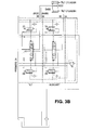
- FIG. 3 illustrates an example hydraulic schematic of a hydraulic system 30 comprising a variable displacement pump 35, a load sensing flow control 34, a load sensing control valve 31, and a hydraulic function valve 33. From the pump configuration it can be seen that the pump flow in the hydraulic system 30 may not be proportional to the engine RPM. Instead, the pump flow may be substantially proportional to the multiplication of the engine RPM and the pump displacement.
- the hydraulic torque load to the engine may be changed.
- the engine anti-stall may be realized.
- FIG. 3 also shows that the displacement of the pump (pump flow rate) may be controlled indirectly.
- the pump flow rate may be controlled, such as by varying the swash plate angle, to maintain the load sense pressure-to-pump pressure ⁇ P at around the specified pump control margin.
- the pump flow rate may be controlled.
- the flow rate command may be calculated according to the operator control input command and the available pump flow model, definition, and/or setting.
- the flow rate commands to the hydraulic operations may be controlled.
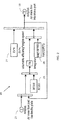
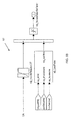
- FIG. 4 is a block diagram illustrating a control system 40 for an industrial vehicle's hydraulic system.
- a microcontroller 36 controls the activation of the E-hydraulic valve 28 according to the engine speed 45 and the command inputs 48 of the operator 32.
- the microcontroller may receive the hydraulic commands 48 from the operator 32 through a device that can be a joystick or an individual lever module. It may also receive the engine speed signal 45, which can be in the form of Revolution Per Minute (RPM), and can be derived from the Engine Control Unit (ECU) through Control Area Network (CAN) or from the measurement of a speed sensor that is directly connected to the microcontroller. Based on these commands and measurements, and the logics programmed in the processing unit, the microcontroller may calculate the flow rate commands, the spool displacements of the E-hydraulic valve 28, and generate the valve commands 49, which can be driving currents.
- RPM Revolution Per Minute
- the E-hydraulic valve 28 may open according to the driving currents from the microcontroller 36. As a result of the valve opening, the load sense signal 47 may be fed to the variable hydraulic pump 14, which may be driven to have nonzero displacement. With nonzero displacement, the variable hydraulic pump 14 may draw power 42 from the engine 12, and supply hydraulic flow 46 to the E-hydraulic valve 28. Based on the openings of different spools, the hydraulic valve may distribute the hydraulic flow 46 to different hydraulic functions 16, 18, 22, 24 and 26.
- the engine 12 may supply torque and maintain its target speed, which is set by the ECU and the operator command.
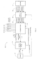
- FIGS. 5A and 5B illustrate a logic diagram for an engine anti-stall control system 50.
- the system 50 may be configured to measure the engine's response to the load, adjust the variable displacement pump's flow rate through controlling the hydraulic valve opening(s), so that the load to the engine is adjusted, and achieve engine anti-stall while achieving maximum control response.
- the system 50 may provide a measured response to sudden loading of the engine at all low engine speed conditions without requiring an anti-stall valve.
- the engine anti-stall control system 50 may be understood to comprise a static sliding mode controller 51, a transient sliding mode controller 53, and a load probe 57.
- the static and transient sliding mode controllers 51, 53 may be configured to adjust the hydraulic torque load to the engine based on the engine revolution speed and acceleration (or deceleration).
- the sliding mode controller(s) may be configured to achieve transient engine anti-stall objectives.
- the static sliding mode controller 51 may be configured to monitor and control aspects of static engine performance associated with the present speed of the engine, e.g., the initial speed of the engine.
- the transient sliding mode controller 53 may be configured to monitor and control aspects of transient engine performance associate with changes in engine speed, e.g., acceleration or deceleration, associated with hydraulic performance or load.
- the load probe 57 may comprise an integrator configured to dynamically estimate the load and limit the maximum pump flow rate.
- the engine anti-stall control system 50 may be used to ensure that the maximum torque demand to the engine does not exceed the available engine torque at different speeds.
- the load probe 57 may be configured to achieve steady-state engine anti-stall objectives.
- the load probe 57 may be understood to integrate the static and transient engine performance operations or responses. Other adjustment or modification components may be used to suppress or reduce system oscillations and to enhance the anti-stall performance, as described further, herein.
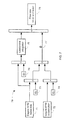
- FIGS. 6A and 6B are simplified diagrams illustrating the engine anti-stall control system 50 as depicted in FIGS. 5A and 5B .
- the diagram 60A may be used to illustrate how the engine anti-stall control system 50 may be configured to operate with an engine and hydraulic system 68.
- a processing device may receive a target engine speed 61 as input.
- the processing device such as a load controller 62, may be configured to identify the initial engine speed of the industrial vehicle.
- the initial engine speed may correspond to the idle engine speed of the industrial vehicle.
- the initial engine speed may correspond to an operation of the industrial vehicle without hydraulic load.
- the processing device further may be configured to monitor a rate of change in engine speed 69.
- Inputs to the load controller 62 may include the magnitude of the change, e.g., decrease, in engine speed, as well as the rate of change, e.g., deceleration rate, of the engine.
- a variable displacement pump may be configured to vary a hydraulic flow associated with the hydraulic system based, in part, on the rate of change in the engine speed 69.
- the control valve e.g., control valve 31 of FIG. 3
- the control valve may comprise a closed center proportional valve 33, an electro-hydraulic proportional valve, a directional control valve, other types of hydraulic valves, or any combination thereof.
- the diagram 60B of FIG. 6B illustrates how this same control concept can be applied with manual or ON/OFF control valves by directly controlling an electro-proportional controlled variable displacement pump 59.
- the load controller 62 may be configured to adjust a valve current 63 associated with the control valve.
- the valve current 63 may in turn be configured to adjust the amount of valve opening 64 of the control valve.
- the load sense flow control 65 may automatically control the pump displacement 66 in response to the hydraulic valve opening 64.
- the hydraulic flow may be varied according to a mapped response to the rate of change in the engine speed.
- the engine speed may be maintained at or below the initial engine speed while the hydraulic flow is varied.
- the adjusted pump displacement 66 may operate to vary the engine torque load 67. For example, increasing the pump displacement 66 may result in an increased engine torque load 67. Decreasing the pump displacement 66 may result in a decreased engine torque load. By adjusting the pump displacement 66, the engine torque load 67 may be adjusted.
- An increase in the engine torque load 67 may result in a reduced engine speed. Conversely, a decrease in the engine torque load 67 may result in an increased engine speed.
- An effect of the change in the engine torque load 67, and similarly of the pump displacement 66, may be measured, compared, or analyzed with respect to the rate of change in the engine speed 69, or engine speed feedback.
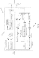
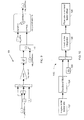
- FIG. 7 is an architectural diagram illustrating the engine anti-stall control system 50 as depicted in FIGS. 5A and 5B .
- the diagram may be used to describe the architecture of the engine anti-stall control system 50.
- ⁇ rpm or the rate of change in engine speed 72, may be defined as the first order time derivative of the engine speed offset e rpm .
- the sliding mode controller 70 may be configured to let the engine states converge to its equilibrium points along this sliding surface. In general control cases, this may be achieved by a Lyapunov method.
- a positive definite Lyapunov function V ( x ) may be defined, wherein the first order derivative of V ( x ) is non-positive definite in the state domain.
- the load probe 76 may comprise an integrator configured to accumulate the offset of the engine speed below idle.
- the maximum hydraulic torque load to the engine may be controlled such that it does not exceed the available engine torque output, e.g., so that the steady state engine anti-stall can be achieved.
- An apparatus may comprise means for identifying the initial engine speed 71 of the industrial vehicle, and means for monitoring the rate of change in engine speed 72.
- the apparatus may comprise means for varying a hydraulic flow 78 associated with a hydraulic system based, in part, on the rate of change in the engine speed, and means for maintaining the engine speed at or below the initial engine speed while the hydraulic flow is being varied.
- the engine speed may be maintained above an engine stall speed while the hydraulic flow is being varied.
- the apparatus may comprise means for measuring an amount of change in the engine speed and a length of time associated with the amount of change in the engine speed to obtain an engine response.
- the hydraulic flow may be varied based, in part, on the engine response.
- a constant hydraulic pressure associated with the hydraulic system may be maintained while the hydraulic flow is varied.
- the amount of change in the engine speed may correspond to a difference between the initial engine speed and an instantaneous engine speed.
- the rate of change in the engine speed may be monitored while the industrial vehicle is lifting a load.
- the rate of change in the engine speed may be monitored while the industrial vehicle is stationary.
- a unique equilibrium point is provided at any one moment. In another embodiment, there may be multiple equilibrium points associated with different loads.
- the engine speed may be stabilized above or equal to the idle speed.
- the engine anti-stall control system described with reference to architectural diagram 70 may comprise a closed-loop system.
- the closed-loop system may be controlled by a PID type controller.
- FIG. 8 is an example look-up table 80 illustrating a hydraulic load factor 85.
- the look-up table 80 may be used instead of, or in place of, a mathematical relationship, such as the Lyapunov function.
- the look-up table 80 may be configured to cause the engine speed to converge at points at or above the engine idle speed.
- the E-hydraulic torque load factor 82 may be defined by a continuous curve. It may be monotonous with respect to the sliding surface 84, or ⁇ .
- FIG. 9 is a logic diagram illustrating an accumulator system 90 configured to accumulate an engine speed offset.
- the accumulator system 90 illustrated as a simulated block diagram, discloses that the load probe may be configured to measure the transient sinking of the engine speed when the E-hydraulic operation is active.
- the value of the transient may monotonously increase with the increase of load. Therefore, the transient value may achieve steady-state equilibrium of the engine power output and the E-hydraulic operation power requirement.
- the load probe and sliding mode control design may be configured to allow relatively higher idle E-hydraulic operation flow rate without having to further adjust for the heaviest rated load associated with the industrial vehicle.
- the load offset may be switched off. Switching off the load offset may provide for full hydraulic operation of the E-hydraulic system regardless of any change in engine speed above an engine stall threshold.
- FIG. 10 is a simplified diagram 100 illustrating the accumulator system 90 depicted in FIG. 9 .
- the engine speed below idle 102 may be provided as input to a deadband filter 104.
- the deadband filter 104 may be used to determine engine revolution acceleration used in the sliding mode control.
- the engine revolution acceleration may be modified by the gain of the time derivative of engine speed 105 as input to the load probe 106.
- the load probe 106 may then be configured to determine a factor offset for the flow rate command.
- the weight of the engine revolution acceleration ⁇ 2 may be defined relatively high.
- the flow rate command factor may fluctuate and result in oscillations in the hydraulic system. Therefore, an engine revolution acceleration dead-band may be applied after nonzero E-hydraulic command is on for a certain period of time.
- n out ⁇ n if t EHyd ⁇ ⁇ transient n filtered if ⁇ t EHyd ⁇ ⁇ transient
- the parameters work jointly to produce a combined effect, and their relative values may be more important than their single value definition.
- the parameters may comprise preset or predefined constants that are determined or established for a particular type or class of industrial vehicles. Different industrial vehicles, e.g., that are rated to transport or handle different load, may be associated with different sets of parameters.
- parameter tuning of the engine anti-stall control system may be described through a table, such as Table 1 shown below: Table 1: Parameter tuning of the engine anti-stall control system Parameters Description Effect to engine anti-stall Effect to oscillation ⁇ 1
- Table 1 Parameter tuning of the engine anti-stall control system Parameters Description Effect to engine anti-stall Effect to oscillation ⁇ 1
- ⁇ 1 The weight of n in the sliding mode surface. It affects the steady-state engine anti-stall: the lower, the less engine anti-stall robust. The higher, the more oscillation.
- the low-pass filter alleviates this issue.
- ⁇ 2 The weight of ⁇ in the sliding mode surface It affects the transient-state engine anti-stall: the lower, the less engine anti-stall robust. The higher, the more oscillation.
- Flow rate factor LUT Defines the flow rate command factor w.r.t. ⁇ .
- ⁇ dead-band The dead-band defined to reduce oscillation when steady-state. The bigger, the less robust the engine anti-stall performance. The bigger, the less oscillation.
- n LPF bandwidth The bandwidth to filter the engine speed signal when steady-state. The bigger, the less robust the engine anti-stall performance. The bigger, the less oscillation.
- FIG. 11 illustrates an example process 110 for varying hydraulic flow to prevent engine stall.
- an initial engine speed of the industrial vehicle may be identified.
- process 110 may be associated with a stationary vehicle, e.g., no or little tractive effort is being applied to industrial vehicle, with the engine operating at low idle speeds.
- a rate of change in engine speed may be monitored.
- the rate of change in engine speed e.g., as measured by the number of revolutions per minute, may reflect the engine's response to the hydraulic load.
- the amount and length of time the engine speed changes, e.g., decreases, may be measured to determine the instantaneous engine performance or response to the hydraulic load.
- a hydraulic pump or a control valve may be controlled to vary a hydraulic flow associated with a hydraulic system based, in part, on the rate of change in the engine speed.
- the hydraulic flow may be varied independent of the hydraulic load.
- the hydraulic flow may be varied without directly measuring engine torque.
- the hydraulic flow may be varied without increasing the engine speed, e.g., without increasing the target or desired engine speed.
- the instantaneous engine speed of the industrial vehicle may be measured.
- the instantaneous engine speed may be multiplied by a first constant to obtain a first input.
- the rate of change in engine speed may be multiplied by a second constant to obtain a second input.
- the first constant and the second constant may comprise fixed constants that are predefined for the industrial vehicle.
- a sliding control may be obtained by combining the first input with the second input.
- the hydraulic flow may be varied based, in part, on the sliding control.
- the engine speed may be maintained at or below the initial engine speed while the hydraulic flow is being varied. In one embodiment, the engine speed may be maintained above an engine stall speed while the hydraulic flow is being varied.
- the initial engine speed generally may be controlled or determined by a position of the accelerator pedal. The engine speed may be controlled independent of hydraulic load, or independent of a hydraulic pressure associated with the load.
- the engine speed may be directly controlled by the accelerator pedal, it may also be indirectly controlled by varying the hydraulic flow.
- the accelerator pedal may control the engine to operate at a target or desired engine speed, such as a low idle speed.
- the engine speed may be maintained at or near the target engine speed, and above the engine stall speed, while performing a hydraulic function such as hoist.
- adjusting the hydraulic flow may be used to assist or maintain the target engine speed as commanded by the accelerator pedal, and avoid engine stall.
- the hydraulic flow may be adjusted, for example decreased, while maintaining substantially the same effective engine performance.
- a constant hydraulic pressure associated with the hydraulic system may be maintained while varying the hydraulic flow.
- the hydraulic flow may be varied by adaptively controlling the variable displacement hydraulic pump as a function of monitored engine speed.
- the hydraulic flow may be varied without modifying the requested engine performance, e.g., as requested by the accelerator pedal.
- the process 110 provides the ability to maximize the hydraulic pump performance within the constraints of the engine performance.
- the engine anti-stall system may be implemented on an internal combustion engine powered E-hydraulic system with a variable displacement pump.
- the hydraulic torque load to the engine may be adjusted based on the engine's speed responses to the hydraulic load, without measuring the load itself.
- the only vehicle system input required to adjust the hydraulic torque load is the engine revolution speed.
- the hydraulic torque load may be adjusted by changing the valve opening and thereby the hydraulic pump flow to control an amount of torque applied to the engine.
- the control valve opening may be controlled by a processing device, e.g., controller, computer, etc., which is configured to execute computer-readable instructions.
- the valve opening is controlled independent of the load, e.g. the weight of the material, being handled by the industrial vehicle.
- the systems, apparatus, and method described herein provide a low cost, efficient, and high hydraulic operation response speed without using additional hardware such as a solenoid valve to drain pump flow when the engine speed is low.
- the system and apparatus described above may use dedicated processor systems, micro controllers, programmable logic devices, or microprocessors that may perform some or all of the operations described herein. Some of the operations described above may be implemented in software and other operations may be implemented in hardware. One or more of the operations, processes, or methods described herein may be performed by an apparatus, device, or system similar to those as described herein and with reference to the illustrated figures.
- the processing device may execute instructions or "code" stored in memory.
- the memory may store data as well.
- the processing device may include, but may not be limited to, an analog processor, a digital processor, a microprocessor, multi-core processor, processor array, network processor, etc.
- the processing device may be part of an integrated control system or system manager, or may be provided as a portable electronic device configured to interface with a networked system either locally or remotely via wireless transmission.
- the processor memory may be integrated together with the processing device, for example RAM or FLASH memory disposed within an integrated circuit microprocessor or the like.
- the memory may comprise an independent device, such as an external disk drive, storage array, or portable FLASH key fob.
- the memory and processing device may be operatively coupled together, or in communication with each other, for example by an I/O port, network connection, etc. such that the processing device may read a file stored on the memory.
- Associated memory may be "read only" by design (ROM) by virtue of permission settings, or not.
- Other examples of memory may include, but may not be limited to, WORM, EPROM, EEPROM, FLASH, etc. which may be implemented in solid state semiconductor devices.
- Other memories may comprise moving parts, such a conventional rotating disk drive. All such memories may be "machine-readable” in that they may be readable by a processing device.
- Operating instructions or commands may be implemented or embodied in tangible forms of stored computer software (also known as a "computer program” or “code”).
- Programs, or code may be stored in a digital memory that may be read by the processing device.
- “Computer-readable storage medium” (or alternatively, “machine-readable storage medium”) may include all of the foregoing types of memory, as well as new technologies that may arise in the future, as long as they may be capable of storing digital information in the nature of a computer program or other data, at least temporarily, in such a manner that the stored information may be "read” by an appropriate processing device.
- the term “computer-readable” may not be limited to the historical usage of "computer” to imply a complete mainframe, mini-computer, desktop or even laptop computer.
- “computer-readable” may comprise storage medium that may be readable by a processor, processing device, or any computing system. Such media may be any available media that may be locally and/or remotely accessible by a computer or processor, and may include volatile and non-volatile media, and removable and non-removable media.
- a program stored in a computer-readable storage medium may comprise a computer program product.
- a storage medium may be used as a convenient means to store or transport a computer program.
- the operations may be described as various interconnected or coupled functional blocks or diagrams. However, there may be cases where these functional blocks or diagrams may be equivalently aggregated into a single logic device, program or operation with unclear boundaries.
Landscapes
- Engineering & Computer Science (AREA)
- Mechanical Engineering (AREA)
- General Engineering & Computer Science (AREA)
- Combustion & Propulsion (AREA)
- Fluid Mechanics (AREA)
- Chemical & Material Sciences (AREA)
- Physics & Mathematics (AREA)
- Transportation (AREA)
- Structural Engineering (AREA)
- Civil Engineering (AREA)
- Life Sciences & Earth Sciences (AREA)
- Geology (AREA)
- Control Of Vehicle Engines Or Engines For Specific Uses (AREA)
- Control Of Transmission Device (AREA)
- Electrical Control Of Air Or Fuel Supplied To Internal-Combustion Engine (AREA)
Applications Claiming Priority (2)
| Application Number | Priority Date | Filing Date | Title |
|---|---|---|---|
| US32697610P | 2010-04-22 | 2010-04-22 | |
| US13/082,290 US20110264335A1 (en) | 2010-04-22 | 2011-04-07 | Robust control for engine anti-stall |
Publications (2)
| Publication Number | Publication Date |
|---|---|
| EP2381081A2 true EP2381081A2 (de) | 2011-10-26 |
| EP2381081A3 EP2381081A3 (de) | 2012-05-02 |
Family
ID=44343675
Family Applications (1)
| Application Number | Title | Priority Date | Filing Date |
|---|---|---|---|
| EP11162553A Withdrawn EP2381081A3 (de) | 2010-04-22 | 2011-04-15 | Robuste Steuerung für Motor-Abwürgschutz |
Country Status (2)
| Country | Link |
|---|---|
| US (1) | US20110264335A1 (de) |
| EP (1) | EP2381081A3 (de) |
Cited By (3)
| Publication number | Priority date | Publication date | Assignee | Title |
|---|---|---|---|---|
| WO2013133892A1 (en) * | 2012-03-07 | 2013-09-12 | Clark Equipment Company | Power management for a drive system |
| CN104150407A (zh) * | 2013-05-13 | 2014-11-19 | 株式会社丰田自动织机 | 工业车辆和用于控制工业车辆的方法 |
| CN113110069A (zh) * | 2021-05-24 | 2021-07-13 | 武汉大学 | 一种基于磁悬浮平面电机迭代神经网络鲁棒控制方法 |
Families Citing this family (11)
| Publication number | Priority date | Publication date | Assignee | Title |
|---|---|---|---|---|
| US9441554B2 (en) * | 2011-03-28 | 2016-09-13 | Honda Motor Co., Ltd. | Control system for internal combustion engine |
| US9316310B2 (en) * | 2011-08-10 | 2016-04-19 | Kubota Corporation | Working machine |
| DE112013000359T5 (de) * | 2013-12-27 | 2015-09-03 | Komatsu Ltd. | Gabelstapler und Steuerungsverfahren für Gabelstapler |
| US9494170B2 (en) * | 2014-02-20 | 2016-11-15 | Oshkosh Corporation | Clutched hydraulic system for a refuse vehicle |
| US10066555B2 (en) | 2015-03-30 | 2018-09-04 | Caterpillar Forest Products Inc. | Hydraulic system and method for controlling same |
| CN105421521B (zh) * | 2015-11-11 | 2018-07-03 | 潍柴动力股份有限公司 | 挖掘机防熄火控制方法及系统 |
| ITUB20160219A1 (it) * | 2016-01-25 | 2017-07-25 | Cnh Ind Italia Spa | Sistema di trasmissione. |
| CN110439695B (zh) * | 2019-08-15 | 2020-08-28 | 济宁医学院 | 工程车辆发动机超速保护控制系统及其控制方法 |
| US12065807B2 (en) * | 2020-07-07 | 2024-08-20 | Danfoss Power Solutions Inc. | Anti-stall system for open circuit systems |
| IT202300010875A1 (it) * | 2023-05-29 | 2024-11-29 | Cnh Ind Italia Spa | Metodo e sistema di controllo di un attuatore idraulico di un veicolo agricolo o da lavoro |
| CN117145640B (zh) * | 2023-10-30 | 2024-01-12 | 潍柴动力股份有限公司 | 发动机控制方法、装置、电子设备及存储介质 |
Family Cites Families (6)
| Publication number | Priority date | Publication date | Assignee | Title |
|---|---|---|---|---|
| US4523892A (en) * | 1984-05-14 | 1985-06-18 | Caterpillar Tractor Co. | Hydrostatic vehicle control |
| US5873427A (en) * | 1997-04-03 | 1999-02-23 | Caterpillar Inc. | Method and apparatus for controlling a load of an engine associated with a hydrostatic drive system |
| JP3868112B2 (ja) * | 1998-05-22 | 2007-01-17 | 株式会社小松製作所 | 油圧駆動機械の制御装置 |
| JP3819699B2 (ja) * | 2000-10-20 | 2006-09-13 | 日立建機株式会社 | 油圧走行車両 |
| JP4145520B2 (ja) * | 2001-11-19 | 2008-09-03 | 本田技研工業株式会社 | 内燃機関のカム位相制御装置 |
| JP3971348B2 (ja) * | 2003-06-25 | 2007-09-05 | 日立建機株式会社 | 建設機械のエンジン制御装置 |
-
2011
- 2011-04-07 US US13/082,290 patent/US20110264335A1/en not_active Abandoned
- 2011-04-15 EP EP11162553A patent/EP2381081A3/de not_active Withdrawn
Non-Patent Citations (1)
| Title |
|---|
| ELBERT HENDRICKS: "Engine Modeling for Control Applications: A Critical Survey", MECCANICA, vol. 32, 1997, pages 387 - 396 |
Cited By (9)
| Publication number | Priority date | Publication date | Assignee | Title |
|---|---|---|---|---|
| WO2013133892A1 (en) * | 2012-03-07 | 2013-09-12 | Clark Equipment Company | Power management for a drive system |
| CN104160183A (zh) * | 2012-03-07 | 2014-11-19 | 克拉克设备公司 | 用于驱动系统的动力管理 |
| US9211808B2 (en) | 2012-03-07 | 2015-12-15 | Clark Equipment Company | Power management for a drive system |
| CN104160183B (zh) * | 2012-03-07 | 2017-08-25 | 克拉克设备公司 | 用于驱动系统的动力管理 |
| CN104150407A (zh) * | 2013-05-13 | 2014-11-19 | 株式会社丰田自动织机 | 工业车辆和用于控制工业车辆的方法 |
| EP2803620A1 (de) * | 2013-05-13 | 2014-11-19 | Kabushiki Kaisha Toyota Jidoshokki | Nutzfahrzeug und Verfahren zur Steuerung eines Nutzfahrzeugs |
| CN104150407B (zh) * | 2013-05-13 | 2016-10-26 | 株式会社丰田自动织机 | 工业车辆和用于控制工业车辆的方法 |
| US9527496B2 (en) | 2013-05-13 | 2016-12-27 | Kabushiki Kaisha Toyota Jidoshokki | Industrial vehicle and method for controlling industrial vehicle |
| CN113110069A (zh) * | 2021-05-24 | 2021-07-13 | 武汉大学 | 一种基于磁悬浮平面电机迭代神经网络鲁棒控制方法 |
Also Published As
| Publication number | Publication date |
|---|---|
| EP2381081A3 (de) | 2012-05-02 |
| US20110264335A1 (en) | 2011-10-27 |
Similar Documents
| Publication | Publication Date | Title |
|---|---|---|
| EP2381081A2 (de) | Robuste Steuerung für Motor-Abwürgschutz | |
| CN100590307C (zh) | 一种液压动力系统的功率控制装置与方法 | |
| US20220356678A1 (en) | Apparatus with hydraulic machine controller | |
| US11261862B2 (en) | Hydrostatic apparatus and method of operating the same | |
| EP3135885A1 (de) | Vorwärtsgekoppelte abluftdrossel und steuerung eines bypassventils für einen motor | |
| US20090223215A1 (en) | Work machine, control system and method for controlling an engine in a work machine | |
| WO2008057177A2 (en) | Method and system for controlling machine power | |
| US10995476B2 (en) | Apparatus | |
| CN103061907B (zh) | 定量泵液压系统的发动机控制装置及方法 | |
| DE102010043237A1 (de) | Kraftmaschinensteuerungssystem mit einem Algorithmus für eine Betätigungseinrichtungssteuerung | |
| US9599107B2 (en) | System and method for controlling a hydrostatic drive unit of a work vehicle using a combination of closed-loop and open-loop control | |
| EP2669498A2 (de) | Verfahren und Vorrichtung zur Steuerung einer Drehmomentlast eines Motors | |
| CN105051292B (zh) | 建筑机械用油压泵控制装置 | |
| WO2014175818A1 (en) | Method and system for control of an internal combustion engine | |
| CN113697673A (zh) | 一种液压控制方法、装置及起重机 | |
| WO2014175820A1 (en) | Method and system for control of an internal combustion engine | |
| EP3754121B1 (de) | Vorrichtung mit einem hydraulischen kreislauf | |
| WO2014175819A1 (en) | Method and system for control of an internal combustion engine | |
| CN105793544B (zh) | 用于调节内燃机转速的方法 | |
| US20240392731A1 (en) | Dual fuel engine system and method for controlling dual fuel engine system | |
| JP5891797B2 (ja) | エンジンの制御装置 | |
| US20250342735A1 (en) | Proportional relief system for a power take-off | |
| US11085527B2 (en) | Using a limiter valve to change pressure in a hydraulic power system | |
| US20250116236A1 (en) | Dual fuel engine system and method for controlling dual fuel engine system | |
| AU2023341377A1 (en) | Dual fuel engine system and method for controlling dual fuel engine system |
Legal Events
| Date | Code | Title | Description |
|---|---|---|---|
| AK | Designated contracting states |
Kind code of ref document: A2 Designated state(s): AL AT BE BG CH CY CZ DE DK EE ES FI FR GB GR HR HU IE IS IT LI LT LU LV MC MK MT NL NO PL PT RO RS SE SI SK SM TR |
|
| AX | Request for extension of the european patent |
Extension state: BA ME |
|
| PUAI | Public reference made under article 153(3) epc to a published international application that has entered the european phase |
Free format text: ORIGINAL CODE: 0009012 |
|
| PUAL | Search report despatched |
Free format text: ORIGINAL CODE: 0009013 |
|
| AK | Designated contracting states |
Kind code of ref document: A3 Designated state(s): AL AT BE BG CH CY CZ DE DK EE ES FI FR GB GR HR HU IE IS IT LI LT LU LV MC MK MT NL NO PL PT RO RS SE SI SK SM TR |
|
| AX | Request for extension of the european patent |
Extension state: BA ME |
|
| RIC1 | Information provided on ipc code assigned before grant |
Ipc: F02D 31/00 20060101ALI20120323BHEP Ipc: B66F 9/22 20060101ALI20120323BHEP Ipc: B60K 28/10 20060101ALI20120323BHEP Ipc: F02D 29/04 20060101AFI20120323BHEP |
|
| STAA | Information on the status of an ep patent application or granted ep patent |
Free format text: STATUS: THE APPLICATION IS DEEMED TO BE WITHDRAWN |
|
| 18D | Application deemed to be withdrawn |
Effective date: 20121103 |