EP2803620A1 - Nutzfahrzeug und Verfahren zur Steuerung eines Nutzfahrzeugs - Google Patents
Nutzfahrzeug und Verfahren zur Steuerung eines Nutzfahrzeugs Download PDFInfo
- Publication number
- EP2803620A1 EP2803620A1 EP20140167294 EP14167294A EP2803620A1 EP 2803620 A1 EP2803620 A1 EP 2803620A1 EP 20140167294 EP20140167294 EP 20140167294 EP 14167294 A EP14167294 A EP 14167294A EP 2803620 A1 EP2803620 A1 EP 2803620A1
- Authority
- EP
- European Patent Office
- Prior art keywords
- threshold value
- hydraulic
- engine
- return passage
- controller
- Prior art date
- Legal status (The legal status is an assumption and is not a legal conclusion. Google has not performed a legal analysis and makes no representation as to the accuracy of the status listed.)
- Granted
Links
Images

Classifications
-
- B—PERFORMING OPERATIONS; TRANSPORTING
- B60—VEHICLES IN GENERAL
- B60W—CONJOINT CONTROL OF VEHICLE SUB-UNITS OF DIFFERENT TYPE OR DIFFERENT FUNCTION; CONTROL SYSTEMS SPECIALLY ADAPTED FOR HYBRID VEHICLES; ROAD VEHICLE DRIVE CONTROL SYSTEMS FOR PURPOSES NOT RELATED TO THE CONTROL OF A PARTICULAR SUB-UNIT
- B60W10/00—Conjoint control of vehicle sub-units of different type or different function
- B60W10/10—Conjoint control of vehicle sub-units of different type or different function including control of change-speed gearings
-
- B—PERFORMING OPERATIONS; TRANSPORTING
- B66—HOISTING; LIFTING; HAULING
- B66F—HOISTING, LIFTING, HAULING OR PUSHING, NOT OTHERWISE PROVIDED FOR, e.g. DEVICES WHICH APPLY A LIFTING OR PUSHING FORCE DIRECTLY TO THE SURFACE OF A LOAD
- B66F9/00—Devices for lifting or lowering bulky or heavy goods for loading or unloading purposes
- B66F9/06—Devices for lifting or lowering bulky or heavy goods for loading or unloading purposes movable, with their loads, on wheels or the like, e.g. fork-lift trucks
- B66F9/075—Constructional features or details
- B66F9/20—Means for actuating or controlling masts, platforms, or forks
- B66F9/22—Hydraulic devices or systems
-
- B—PERFORMING OPERATIONS; TRANSPORTING
- B60—VEHICLES IN GENERAL
- B60W—CONJOINT CONTROL OF VEHICLE SUB-UNITS OF DIFFERENT TYPE OR DIFFERENT FUNCTION; CONTROL SYSTEMS SPECIALLY ADAPTED FOR HYBRID VEHICLES; ROAD VEHICLE DRIVE CONTROL SYSTEMS FOR PURPOSES NOT RELATED TO THE CONTROL OF A PARTICULAR SUB-UNIT
- B60W10/00—Conjoint control of vehicle sub-units of different type or different function
- B60W10/04—Conjoint control of vehicle sub-units of different type or different function including control of propulsion units
- B60W10/06—Conjoint control of vehicle sub-units of different type or different function including control of propulsion units including control of combustion engines
Definitions
- the present invention relates to an industrial vehicle including a hydraulic actuator and a hydraulic pump that is driven by an engine and a method for controlling the industrial vehicle.
- a forklift is one example of an industrial vehicle that includes an engine, a hydraulic pump driven by the engine, and a hydraulic mechanism that operates a hydraulic actuator by hydraulic oil discharged from the hydraulic pump.
- the forklift includes, for example, a lifting hydraulic cylinder, which is a hydraulic actuator that lifts and lowers forks, and a tilting hydraulic cylinder, which is a hydraulic actuator that tilts a mast.
- a lifting hydraulic cylinder which is a hydraulic actuator that lifts and lowers forks
- a tilting hydraulic cylinder which is a hydraulic actuator that tilts a mast.
- the structure of the '137 publication opens a discharge pipe of the hydraulic pump after detecting a reduction in the engine speed.
- the engine speed is further reduced before the load on the hydraulic pump is reduced by opening the discharge pipe.
- the structure of the '137 publication fails to obviate engine stalling.
- one aspect of the present invention is an industrial vehicle that includes an engine, a hydraulic actuator, a hydraulic pump driven by the engine, and an instruction member operated to instruct operation of the hydraulic actuator.
- a supply passage is adapted to supply hydraulic oil discharged from the hydraulic pump to the hydraulic actuator.
- a return passage is adapted to return the hydraulic oil discharged from the hydraulic pump to an oil tank.
- a controller is adapted to compare an engine speed and a predetermined comparison threshold value. The controller is adapted so that when the engine speed is less than the comparison threshold value, the controller opens the return passage so that the hydraulic oil flows through the return passage.
- the comparison threshold value includes a first threshold value and a second threshold value that is lower than the first threshold value.
- the controller is adapted to, in response to the operation of the instruction member, open the return passage so that the hydraulic oil flows through the return passage, perform revving control to increase the engine speed, and change the comparison threshold value from the first threshold value to the second threshold value.
- Another aspect of the present invention is a method for controlling an industrial vehicle that includes an engine, a hydraulic actuator, a hydraulic pump driven by the engine, an instruction member operated to instruct operation of the hydraulic actuator, a supply passage that supplies hydraulic oil discharged from the hydraulic pump to the hydraulic actuator, and a return passage that returns the hydraulic oil discharged from the hydraulic pump to an oil tank.
- the method includes when the engine speed is less than the comparison threshold value, opening the return passage so that the hydraulic oil flows through the return passage, in response to the operation of the instruction member, opening the return passage so that the hydraulic oil flows through the return passage, performing revving control to increase the engine speed, and changing the comparison threshold value from a first threshold value to a second threshold value that is lower than the first threshold value.
- a forklift 10 which is an industrial vehicle, includes a material handling device 11 coupled to the vehicle body of the forklift 10.
- the material handling device 11 includes a multistage mast 14 including right and left outer mast members 12 and an inner mast member 13.
- the outer mast members 12 are coupled to a hydraulic tilt cylinder 15, which functions as a hydraulic actuator.
- the inner mast member 13 is coupled to a hydraulic lift cylinder 16, which functions as a hydraulic actuator.
- the mast 14 is tilted forward or rearward when hydraulic oil is supplied to or discharged from the tilt cylinder 15.
- the inner mast member 13 is lifted or lowered in the vertical direction when hydraulic oil is supplied to or discharged from the lift cylinder 16.
- a lift bracket 17 couples a fork 18 to the inner mast member 13.
- the fork 18 is lifted and lowered with the lift bracket 17 when the inner mast member 13 is lifted or lowered by the lift cylinder 16 along the outer mast members 12.
- the forklift 10 includes, in the vehicle body, an engine 19, which serves as a driving source for the forklift 10 when driven and when handling material, a hydraulic pump 20, which is driven by the engine 19, and a hydraulic mechanism 21, which is supplied with hydraulic oil discharged from the hydraulic pump 20.
- the hydraulic mechanism 21 includes control valves 22 and 23 and an unload valve 24.
- the control valve 22 controls the supply and discharge of hydraulic oil to and from the tilt cylinder 15.
- the control valve 22 is mechanically coupled to a tilt operation member 25, which functions as an instruction member that is operated to instruct operation of the tilt cylinder 15. Operation of the tilt operation member 25 opens and closes the control valve 22.
- the control valve 23 controls the supply and discharge of hydraulic oil to and from the lift cylinder 16.
- the control valve 23 is mechanically coupled to a lift operation member 26, which functions as an instruction member that is operated to instruct operation of the lift cylinder 16. Operation of the lift operation member 26 opens and closes the control valve 23.
- the tilt operation member 25 and the lift operation member 26 are located in the operator cab of the forklift 10 and operable by the operator of the forklift 10.
- the unload valve 24 controls the discharge of hydraulic oil from the hydraulic pump 20 to an oil tank 27 arranged in the vehicle body.
- the forklift 10 also includes a controller 28 in the vehicle body.
- the controller 28 controls the engine speed and opens and closes the unload valve 24 based on a detection signal received from a speed sensor 29 that detects the engine speed. Further, the controller 28 is electrically connected to a detection sensor 25a, which detects the operation state of the tilt operation member 25, and a detection sensor 26a, which detects the operation state of the lift operation member 26.
- the controller 28 detects the depression amount (accelerator operation amount) of an accelerator member (accelerator pedal) 30, which is operated by the operator to accelerate the forklift 10.
- the controller 28 controls the engine speed in accordance with the depression amount of the accelerator member 30.
- the hydraulic pump 20 In the forklift 10 in which the hydraulic pump 20 is driven by the engine 19, the operator operates the tilt cylinder 15 and the lift cylinder 16 by operating the tilt operation member 25 and the lift operation member 26 while depressing the accelerator member 30.
- the hydraulic pump 20 draws hydraulic oil from the oil tank 27 and then discharges the hydraulic oil. The flow of the hydraulic oil will now be described.
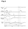
- the controller 28 sets a first threshold value Y1 as a comparison threshold value compared with the speed of the engine 19.
- the controller 28 switches the unload valve 24 to the second position to open a return passage that returns the hydraulic oil from the hydraulic pump 20 to the oil tank 27.
- the controller 28 opens the return passage when the engine speed is below the first threshold value Y1.
- the accelerator member 30, the tilt operation member 25, and the lift operation member 26 are not operated and the hydraulic pump 20 is free from loads.
- the engine 19 is driven in accordance with a speed instruction X1 issued by the controller 28.
- the speed instruction X1 drives the engine 19 at an idling speed.
- the controller 28 when detecting the input of a signal based on the operation of the tilt operation member 25 or the lift operation member 26, the controller 28 outputs an unload instruction that switches the unload valve 24 to the second position to open the return passage.
- the hydraulic oil returns to the oil tank 27 without being supplied to the control valves 22 and 23.
- the return passage includes the unload valve 24 and the oil passage 35.
- the controller 28 continues to output the unload instruction until the engine speed reaches the predetermined value or until time T1 ends.
- the unload valve 24 returns to the first position and opens a supply passage, which supplies the tilt cylinder 15 and the lift cylinder 16 with hydraulic oil from the hydraulic pump 20.
- the hydraulic oil flows to the control valves 22 and 23 and is supplied to the tilt cylinder 15 and the lift cylinder 16.
- the supply passage includes the oil passage 32, the control valves 22 and 23, and the oil passages 33 and 34.
- the controller 28 In addition to the unload instruction, the controller 28 outputs a speed instruction X2 to perform a revving control that increases the engine speed.
- the speed instruction X2 drives the engine 19 at a higher speed than the speed specified by the speed instruction X1.
- the controller 28 outputs the speed instruction X2 for the duration of time T2.
- the load on the hydraulic pump 20 is reduced by opening the return passage and performing the revving control.
- the torque of the engine 19 remains sufficient since the load on the hydraulic pump 20 does not increase.
- engine stalling is avoided in the forklift 10 of the present embodiment.
- the controller 28 when outputting the unload instruction and the speed instruction X2, the controller 28 changes the comparison threshold value to a second threshold value Y2, which is lower than the first threshold value Y1.
- the engine 19 is being controlled to avoid engine stalling as described above, when the output of the unload instruction is stopped, the supply passage opens and increases the load on the hydraulic pump 20. This reduces the engine speed.
- the controller 28 would output the unload instruction again, as shown by the single-dashed lines in Fig. 2 .
- the output of the unload instruction would stop the tilt cylinder 15 or the lift cylinder 16 that has just started to operate. Such unstable operation may interrupt material handling and hinder adjustment of material handling position.
- the comparison threshold value is set to the second threshold value Y2, which is lower than the first threshold value Y1.
- the controller 28 After outputting the speed instruction X2 over time T2, the controller 28 stops the revving control and gradually reduces the value of the speed instruction to the value of the speed instruction X1. When stopping the revving control, the controller 28 also gradually increases the comparison threshold value to the first threshold value Y1.
- the tilt operation member 25 or the lift operation member 26 is continuously operated.
- the controller 28 outputs the unload instruction when the engine speed becomes lower than the first threshold value Y1.
- the tilt operation member 25 or the lift operation member 26 is continuously operated like in period C and the engine speed is reduced, or the load on the hydraulic pump is increased, for example, the hydraulic cylinder may have reached the stroke end position.
- the controller 28 outputs the unload instruction to reduce the load on the hydraulic pump 20 and avoid engine stalling.
- the comparison threshold value includes the first and second threshold values Y1 and Y2.
- the comparison threshold value is returned to the first threshold value Y1, which is higher than the second threshold value Y2. This results in an earlier output of the unload instruction.
- the control valves 22 and 23 may be electromagnetic valves.
- the controller 28 may send signals to open and close the electromagnetic valves. In this case, when the tilt operation member 25 and the lift operation member 26 are not operated, the hydraulic oil is continuously discharged to the oil tank 27 through the return passage. When detecting operation of the tilt operation member 25 or the lift operation member 26, the controller 28 holds the control valves 22 and 23 for a predetermined time to continue the discharge of hydraulic oil through the return passage. Then, after the predetermined time, the controller 28 controls the control valves 22 and 23 to open the supply passage. The controller 28 also performs the revving control on the engine 19 and changes the comparison threshold value.
- This embodiment has the same advantages as the embodiment described above.
- the comparison threshold value When gradually increasing the comparison threshold value to the first threshold value Y1 after the controller 28 stops the revving control, the comparison threshold value may be increased linearly or may be increased in step by step.
- the hydraulic actuator is not limited to the lifting hydraulic cylinder and the tiling hydraulic cylinder and may be a different hydraulic cylinder such as one that moves an attachment of the forklift 10. Further, the hydraulic actuator may be a hydraulic power steering device.
- the speed instruction may be returned to the speed instruction X1 when the time T2 ends.
- the comparison threshold value may be returned to the first threshold value Y1 when the revving control ends.
- the industrial vehicle may include a single hydraulic actuator or three or more hydraulic actuators.
- the control of the present embodiment is applicable to industrial vehicles other than forklifts.
- An industrial vehicle that includes an engine, a hydraulic actuator, a hydraulic pump, and an instruction member operated to instruct operation of the hydraulic actuator.
- a supply passage supplies hydraulic oil to the hydraulic actuator.
- a return passage returns return the hydraulic oil to an oil tank.
- a controller compares an engine speed and a predetermined comparison threshold value. When the engine speed is less than the comparison threshold value, the controller opens the return passage.
- the comparison threshold value includes a first threshold value and a second threshold value that is lower than the first threshold value.
- the controller opens the return passage, performs revving control to increase the engine speed, and changes the comparison threshold value from the first threshold value to the second threshold value.
Landscapes
- Engineering & Computer Science (AREA)
- Chemical & Material Sciences (AREA)
- Combustion & Propulsion (AREA)
- Transportation (AREA)
- Mechanical Engineering (AREA)
- Structural Engineering (AREA)
- Civil Engineering (AREA)
- Life Sciences & Earth Sciences (AREA)
- Geology (AREA)
- Forklifts And Lifting Vehicles (AREA)
- Fluid-Pressure Circuits (AREA)
Applications Claiming Priority (1)
| Application Number | Priority Date | Filing Date | Title |
|---|---|---|---|
| JP2013101443A JP6007858B2 (ja) | 2013-05-13 | 2013-05-13 | 産業車両 |
Publications (2)
| Publication Number | Publication Date |
|---|---|
| EP2803620A1 true EP2803620A1 (de) | 2014-11-19 |
| EP2803620B1 EP2803620B1 (de) | 2016-02-03 |
Family
ID=50679899
Family Applications (1)
| Application Number | Title | Priority Date | Filing Date |
|---|---|---|---|
| EP14167294.9A Active EP2803620B1 (de) | 2013-05-13 | 2014-05-07 | Nutzfahrzeug und Verfahren zur Steuerung eines Nutzfahrzeugs |
Country Status (4)
| Country | Link |
|---|---|
| US (1) | US9527496B2 (de) |
| EP (1) | EP2803620B1 (de) |
| JP (1) | JP6007858B2 (de) |
| CN (1) | CN104150407B (de) |
Families Citing this family (1)
| Publication number | Priority date | Publication date | Assignee | Title |
|---|---|---|---|---|
| KR102026068B1 (ko) * | 2014-12-31 | 2019-09-27 | 주식회사 두산 | 지게차 엔진의 아이들 스피드 제어 장치 및 제어 방법 |
Citations (3)
| Publication number | Priority date | Publication date | Assignee | Title |
|---|---|---|---|---|
| EP2075217A2 (de) * | 2007-12-25 | 2009-07-01 | Nissan Motor Co., Ltd. | Industrielles Fahrzeug |
| EP2381081A2 (de) * | 2010-04-22 | 2011-10-26 | NACCO Materials Handling Group, Inc. | Robuste Steuerung für Motor-Abwürgschutz |
| WO2012036187A1 (ja) * | 2010-09-14 | 2012-03-22 | 三菱重工業株式会社 | 産業車両 |
Family Cites Families (4)
| Publication number | Priority date | Publication date | Assignee | Title |
|---|---|---|---|---|
| JP2002012398A (ja) * | 2000-06-29 | 2002-01-15 | Komatsu Forklift Co Ltd | フォークリフトトラックの作業機における作動回路装置 |
| JP2004324694A (ja) * | 2003-04-22 | 2004-11-18 | Sumitomo (Shi) Construction Machinery Manufacturing Co Ltd | 建設機械の油圧回路 |
| US7484814B2 (en) * | 2006-03-03 | 2009-02-03 | Husco International, Inc. | Hydraulic system with engine anti-stall control |
| JP5029244B2 (ja) * | 2007-09-20 | 2012-09-19 | 株式会社豊田自動織機 | 産業車両の荷役制御装置 |
-
2013
- 2013-05-13 JP JP2013101443A patent/JP6007858B2/ja active Active
-
2014
- 2014-05-07 US US14/271,608 patent/US9527496B2/en active Active
- 2014-05-07 EP EP14167294.9A patent/EP2803620B1/de active Active
- 2014-05-09 CN CN201410195771.0A patent/CN104150407B/zh active Active
Patent Citations (4)
| Publication number | Priority date | Publication date | Assignee | Title |
|---|---|---|---|---|
| EP2075217A2 (de) * | 2007-12-25 | 2009-07-01 | Nissan Motor Co., Ltd. | Industrielles Fahrzeug |
| EP2381081A2 (de) * | 2010-04-22 | 2011-10-26 | NACCO Materials Handling Group, Inc. | Robuste Steuerung für Motor-Abwürgschutz |
| WO2012036187A1 (ja) * | 2010-09-14 | 2012-03-22 | 三菱重工業株式会社 | 産業車両 |
| JP2012062137A (ja) | 2010-09-14 | 2012-03-29 | Mitsubishi Heavy Ind Ltd | 産業車両 |
Also Published As
| Publication number | Publication date |
|---|---|
| CN104150407B (zh) | 2016-10-26 |
| CN104150407A (zh) | 2014-11-19 |
| JP2014221681A (ja) | 2014-11-27 |
| JP6007858B2 (ja) | 2016-10-12 |
| US9527496B2 (en) | 2016-12-27 |
| EP2803620B1 (de) | 2016-02-03 |
| US20140336002A1 (en) | 2014-11-13 |
Similar Documents
| Publication | Publication Date | Title |
|---|---|---|
| EP2803619B2 (de) | Nutzfahrzeug und Verfahren zur Steuerung von einem industriellen Fahrzeug | |
| US7810323B2 (en) | Load control device for engine of work vehicle | |
| EP2538121A1 (de) | Nutzfahrzeug und steuerverfahren für ein nutzfahrzeug | |
| EP2923995B1 (de) | Nutzfahrzeug | |
| EP2803620B1 (de) | Nutzfahrzeug und Verfahren zur Steuerung eines Nutzfahrzeugs | |
| EP2821361B1 (de) | Industriefahrzeug | |
| EP2930077B1 (de) | Fahrzeug mit einer hydraulisch betätigten vorrichtung | |
| EP2918541A1 (de) | Fahrsteuerungsvorrichtung für industriefahrzeuge | |
| EP3222578B1 (de) | Lastfahrzeug | |
| EP2923993B1 (de) | Leistungsregelungsvorrichtung für frachtumschlagfahrzeug | |
| JP2001206699A (ja) | 産業車両の作業機制御方法及び作業機制御装置 | |
| JP6488990B2 (ja) | 荷役車両の油圧駆動装置 |
Legal Events
| Date | Code | Title | Description |
|---|---|---|---|
| PUAI | Public reference made under article 153(3) epc to a published international application that has entered the european phase |
Free format text: ORIGINAL CODE: 0009012 |
|
| 17P | Request for examination filed |
Effective date: 20140507 |
|
| AK | Designated contracting states |
Kind code of ref document: A1 Designated state(s): AL AT BE BG CH CY CZ DE DK EE ES FI FR GB GR HR HU IE IS IT LI LT LU LV MC MK MT NL NO PL PT RO RS SE SI SK SM TR |
|
| AX | Request for extension of the european patent |
Extension state: BA ME |
|
| RIC1 | Information provided on ipc code assigned before grant |
Ipc: B60W 10/06 20060101ALI20150420BHEP Ipc: B60W 10/10 20120101ALI20150420BHEP Ipc: B66F 9/22 20060101AFI20150420BHEP |
|
| GRAP | Despatch of communication of intention to grant a patent |
Free format text: ORIGINAL CODE: EPIDOSNIGR1 |
|
| INTG | Intention to grant announced |
Effective date: 20150715 |
|
| GRAS | Grant fee paid |
Free format text: ORIGINAL CODE: EPIDOSNIGR3 |
|
| GRAA | (expected) grant |
Free format text: ORIGINAL CODE: 0009210 |
|
| AK | Designated contracting states |
Kind code of ref document: B1 Designated state(s): AL AT BE BG CH CY CZ DE DK EE ES FI FR GB GR HR HU IE IS IT LI LT LU LV MC MK MT NL NO PL PT RO RS SE SI SK SM TR |
|
| REG | Reference to a national code |
Ref country code: GB Ref legal event code: FG4D |
|
| REG | Reference to a national code |
Ref country code: AT Ref legal event code: REF Ref document number: 773606 Country of ref document: AT Kind code of ref document: T Effective date: 20160215 Ref country code: CH Ref legal event code: EP |
|
| REG | Reference to a national code |
Ref country code: IE Ref legal event code: FG4D |
|
| REG | Reference to a national code |
Ref country code: DE Ref legal event code: R096 Ref document number: 602014000827 Country of ref document: DE |
|
| REG | Reference to a national code |
Ref country code: DE Ref legal event code: R082 Ref document number: 602014000827 Country of ref document: DE Representative=s name: TBK, DE |
|
| REG | Reference to a national code |
Ref country code: FR Ref legal event code: PLFP Year of fee payment: 3 |
|
| REG | Reference to a national code |
Ref country code: LT Ref legal event code: MG4D Ref country code: NL Ref legal event code: MP Effective date: 20160203 |
|
| REG | Reference to a national code |
Ref country code: AT Ref legal event code: MK05 Ref document number: 773606 Country of ref document: AT Kind code of ref document: T Effective date: 20160203 |
|
| PG25 | Lapsed in a contracting state [announced via postgrant information from national office to epo] |
Ref country code: HR Free format text: LAPSE BECAUSE OF FAILURE TO SUBMIT A TRANSLATION OF THE DESCRIPTION OR TO PAY THE FEE WITHIN THE PRESCRIBED TIME-LIMIT Effective date: 20160203 Ref country code: NO Free format text: LAPSE BECAUSE OF FAILURE TO SUBMIT A TRANSLATION OF THE DESCRIPTION OR TO PAY THE FEE WITHIN THE PRESCRIBED TIME-LIMIT Effective date: 20160503 Ref country code: FI Free format text: LAPSE BECAUSE OF FAILURE TO SUBMIT A TRANSLATION OF THE DESCRIPTION OR TO PAY THE FEE WITHIN THE PRESCRIBED TIME-LIMIT Effective date: 20160203 Ref country code: GR Free format text: LAPSE BECAUSE OF FAILURE TO SUBMIT A TRANSLATION OF THE DESCRIPTION OR TO PAY THE FEE WITHIN THE PRESCRIBED TIME-LIMIT Effective date: 20160504 Ref country code: ES Free format text: LAPSE BECAUSE OF FAILURE TO SUBMIT A TRANSLATION OF THE DESCRIPTION OR TO PAY THE FEE WITHIN THE PRESCRIBED TIME-LIMIT Effective date: 20160203 |
|
| PG25 | Lapsed in a contracting state [announced via postgrant information from national office to epo] |
Ref country code: AT Free format text: LAPSE BECAUSE OF FAILURE TO SUBMIT A TRANSLATION OF THE DESCRIPTION OR TO PAY THE FEE WITHIN THE PRESCRIBED TIME-LIMIT Effective date: 20160203 Ref country code: RS Free format text: LAPSE BECAUSE OF FAILURE TO SUBMIT A TRANSLATION OF THE DESCRIPTION OR TO PAY THE FEE WITHIN THE PRESCRIBED TIME-LIMIT Effective date: 20160203 Ref country code: LV Free format text: LAPSE BECAUSE OF FAILURE TO SUBMIT A TRANSLATION OF THE DESCRIPTION OR TO PAY THE FEE WITHIN THE PRESCRIBED TIME-LIMIT Effective date: 20160203 Ref country code: LT Free format text: LAPSE BECAUSE OF FAILURE TO SUBMIT A TRANSLATION OF THE DESCRIPTION OR TO PAY THE FEE WITHIN THE PRESCRIBED TIME-LIMIT Effective date: 20160203 Ref country code: NL Free format text: LAPSE BECAUSE OF FAILURE TO SUBMIT A TRANSLATION OF THE DESCRIPTION OR TO PAY THE FEE WITHIN THE PRESCRIBED TIME-LIMIT Effective date: 20160203 Ref country code: IS Free format text: LAPSE BECAUSE OF FAILURE TO SUBMIT A TRANSLATION OF THE DESCRIPTION OR TO PAY THE FEE WITHIN THE PRESCRIBED TIME-LIMIT Effective date: 20160603 Ref country code: PT Free format text: LAPSE BECAUSE OF FAILURE TO SUBMIT A TRANSLATION OF THE DESCRIPTION OR TO PAY THE FEE WITHIN THE PRESCRIBED TIME-LIMIT Effective date: 20160603 Ref country code: BE Free format text: LAPSE BECAUSE OF NON-PAYMENT OF DUE FEES Effective date: 20160531 Ref country code: SE Free format text: LAPSE BECAUSE OF FAILURE TO SUBMIT A TRANSLATION OF THE DESCRIPTION OR TO PAY THE FEE WITHIN THE PRESCRIBED TIME-LIMIT Effective date: 20160203 Ref country code: PL Free format text: LAPSE BECAUSE OF FAILURE TO SUBMIT A TRANSLATION OF THE DESCRIPTION OR TO PAY THE FEE WITHIN THE PRESCRIBED TIME-LIMIT Effective date: 20160203 |
|
| PG25 | Lapsed in a contracting state [announced via postgrant information from national office to epo] |
Ref country code: DK Free format text: LAPSE BECAUSE OF FAILURE TO SUBMIT A TRANSLATION OF THE DESCRIPTION OR TO PAY THE FEE WITHIN THE PRESCRIBED TIME-LIMIT Effective date: 20160203 Ref country code: EE Free format text: LAPSE BECAUSE OF FAILURE TO SUBMIT A TRANSLATION OF THE DESCRIPTION OR TO PAY THE FEE WITHIN THE PRESCRIBED TIME-LIMIT Effective date: 20160203 |
|
| REG | Reference to a national code |
Ref country code: DE Ref legal event code: R097 Ref document number: 602014000827 Country of ref document: DE |
|
| PG25 | Lapsed in a contracting state [announced via postgrant information from national office to epo] |
Ref country code: SK Free format text: LAPSE BECAUSE OF FAILURE TO SUBMIT A TRANSLATION OF THE DESCRIPTION OR TO PAY THE FEE WITHIN THE PRESCRIBED TIME-LIMIT Effective date: 20160203 Ref country code: RO Free format text: LAPSE BECAUSE OF FAILURE TO SUBMIT A TRANSLATION OF THE DESCRIPTION OR TO PAY THE FEE WITHIN THE PRESCRIBED TIME-LIMIT Effective date: 20160203 Ref country code: SM Free format text: LAPSE BECAUSE OF FAILURE TO SUBMIT A TRANSLATION OF THE DESCRIPTION OR TO PAY THE FEE WITHIN THE PRESCRIBED TIME-LIMIT Effective date: 20160203 Ref country code: CZ Free format text: LAPSE BECAUSE OF FAILURE TO SUBMIT A TRANSLATION OF THE DESCRIPTION OR TO PAY THE FEE WITHIN THE PRESCRIBED TIME-LIMIT Effective date: 20160203 |
|
| PLBE | No opposition filed within time limit |
Free format text: ORIGINAL CODE: 0009261 |
|
| STAA | Information on the status of an ep patent application or granted ep patent |
Free format text: STATUS: NO OPPOSITION FILED WITHIN TIME LIMIT |
|
| PG25 | Lapsed in a contracting state [announced via postgrant information from national office to epo] |
Ref country code: LU Free format text: LAPSE BECAUSE OF FAILURE TO SUBMIT A TRANSLATION OF THE DESCRIPTION OR TO PAY THE FEE WITHIN THE PRESCRIBED TIME-LIMIT Effective date: 20160507 Ref country code: BE Free format text: LAPSE BECAUSE OF FAILURE TO SUBMIT A TRANSLATION OF THE DESCRIPTION OR TO PAY THE FEE WITHIN THE PRESCRIBED TIME-LIMIT Effective date: 20160203 |
|
| 26N | No opposition filed |
Effective date: 20161104 |
|
| REG | Reference to a national code |
Ref country code: IE Ref legal event code: MM4A |
|
| PG25 | Lapsed in a contracting state [announced via postgrant information from national office to epo] |
Ref country code: SI Free format text: LAPSE BECAUSE OF FAILURE TO SUBMIT A TRANSLATION OF THE DESCRIPTION OR TO PAY THE FEE WITHIN THE PRESCRIBED TIME-LIMIT Effective date: 20160203 Ref country code: BG Free format text: LAPSE BECAUSE OF FAILURE TO SUBMIT A TRANSLATION OF THE DESCRIPTION OR TO PAY THE FEE WITHIN THE PRESCRIBED TIME-LIMIT Effective date: 20160503 |
|
| REG | Reference to a national code |
Ref country code: FR Ref legal event code: PLFP Year of fee payment: 4 |
|
| PG25 | Lapsed in a contracting state [announced via postgrant information from national office to epo] |
Ref country code: IE Free format text: LAPSE BECAUSE OF NON-PAYMENT OF DUE FEES Effective date: 20160507 |
|
| REG | Reference to a national code |
Ref country code: CH Ref legal event code: PL |
|
| PG25 | Lapsed in a contracting state [announced via postgrant information from national office to epo] |
Ref country code: LI Free format text: LAPSE BECAUSE OF NON-PAYMENT OF DUE FEES Effective date: 20170531 Ref country code: CH Free format text: LAPSE BECAUSE OF NON-PAYMENT OF DUE FEES Effective date: 20170531 |
|
| REG | Reference to a national code |
Ref country code: FR Ref legal event code: PLFP Year of fee payment: 5 |
|
| PG25 | Lapsed in a contracting state [announced via postgrant information from national office to epo] |
Ref country code: HU Free format text: LAPSE BECAUSE OF FAILURE TO SUBMIT A TRANSLATION OF THE DESCRIPTION OR TO PAY THE FEE WITHIN THE PRESCRIBED TIME-LIMIT; INVALID AB INITIO Effective date: 20140507 |
|
| PG25 | Lapsed in a contracting state [announced via postgrant information from national office to epo] |
Ref country code: CY Free format text: LAPSE BECAUSE OF FAILURE TO SUBMIT A TRANSLATION OF THE DESCRIPTION OR TO PAY THE FEE WITHIN THE PRESCRIBED TIME-LIMIT Effective date: 20160203 Ref country code: MC Free format text: LAPSE BECAUSE OF FAILURE TO SUBMIT A TRANSLATION OF THE DESCRIPTION OR TO PAY THE FEE WITHIN THE PRESCRIBED TIME-LIMIT Effective date: 20160203 Ref country code: MK Free format text: LAPSE BECAUSE OF FAILURE TO SUBMIT A TRANSLATION OF THE DESCRIPTION OR TO PAY THE FEE WITHIN THE PRESCRIBED TIME-LIMIT Effective date: 20160203 Ref country code: MT Free format text: LAPSE BECAUSE OF NON-PAYMENT OF DUE FEES Effective date: 20160531 |
|
| PG25 | Lapsed in a contracting state [announced via postgrant information from national office to epo] |
Ref country code: TR Free format text: LAPSE BECAUSE OF FAILURE TO SUBMIT A TRANSLATION OF THE DESCRIPTION OR TO PAY THE FEE WITHIN THE PRESCRIBED TIME-LIMIT Effective date: 20160203 Ref country code: AL Free format text: LAPSE BECAUSE OF FAILURE TO SUBMIT A TRANSLATION OF THE DESCRIPTION OR TO PAY THE FEE WITHIN THE PRESCRIBED TIME-LIMIT Effective date: 20160203 |
|
| GBPC | Gb: european patent ceased through non-payment of renewal fee |
Effective date: 20180507 |
|
| PG25 | Lapsed in a contracting state [announced via postgrant information from national office to epo] |
Ref country code: GB Free format text: LAPSE BECAUSE OF NON-PAYMENT OF DUE FEES Effective date: 20180507 |
|
| REG | Reference to a national code |
Ref country code: FR Ref legal event code: PLFP Year of fee payment: 10 |
|
| P01 | Opt-out of the competence of the unified patent court (upc) registered |
Effective date: 20230519 |
|
| PGFP | Annual fee paid to national office [announced via postgrant information from national office to epo] |
Ref country code: DE Payment date: 20250402 Year of fee payment: 12 |
|
| PGFP | Annual fee paid to national office [announced via postgrant information from national office to epo] |
Ref country code: IT Payment date: 20250422 Year of fee payment: 12 |
|
| PGFP | Annual fee paid to national office [announced via postgrant information from national office to epo] |
Ref country code: FR Payment date: 20250401 Year of fee payment: 12 |