EP2381090A2 - Hebelwirkung maximierendes Wasserrad mit vertikale Achse - Google Patents
Hebelwirkung maximierendes Wasserrad mit vertikale Achse Download PDFInfo
- Publication number
- EP2381090A2 EP2381090A2 EP10165597A EP10165597A EP2381090A2 EP 2381090 A2 EP2381090 A2 EP 2381090A2 EP 10165597 A EP10165597 A EP 10165597A EP 10165597 A EP10165597 A EP 10165597A EP 2381090 A2 EP2381090 A2 EP 2381090A2
- Authority
- EP
- European Patent Office
- Prior art keywords
- spoke
- spokes
- vertical axis
- water level
- rotor device
- Prior art date
- Legal status (The legal status is an assumption and is not a legal conclusion. Google has not performed a legal analysis and makes no representation as to the accuracy of the status listed.)
- Withdrawn
Links
- XLYOFNOQVPJJNP-UHFFFAOYSA-N water Substances O XLYOFNOQVPJJNP-UHFFFAOYSA-N 0.000 claims abstract description 107
- 238000010276 construction Methods 0.000 claims description 30
- 238000007667 floating Methods 0.000 claims description 20
- 239000000463 material Substances 0.000 claims description 5
- 239000012530 fluid Substances 0.000 claims description 4
- 230000005611 electricity Effects 0.000 abstract description 3
- 230000005540 biological transmission Effects 0.000 description 6
- 210000003141 lower extremity Anatomy 0.000 description 6
- 238000012423 maintenance Methods 0.000 description 4
- 230000000284 resting effect Effects 0.000 description 4
- 210000001364 upper extremity Anatomy 0.000 description 4
- 238000005516 engineering process Methods 0.000 description 3
- 230000001419 dependent effect Effects 0.000 description 2
- 230000000694 effects Effects 0.000 description 2
- 210000003414 extremity Anatomy 0.000 description 2
- 244000228957 Ferula foetida Species 0.000 description 1
- 230000004075 alteration Effects 0.000 description 1
- 238000007664 blowing Methods 0.000 description 1
- 230000002452 interceptive effect Effects 0.000 description 1
- 238000004519 manufacturing process Methods 0.000 description 1
- 230000004048 modification Effects 0.000 description 1
- 238000012986 modification Methods 0.000 description 1
- 239000000126 substance Substances 0.000 description 1
Images







Classifications
-
- F—MECHANICAL ENGINEERING; LIGHTING; HEATING; WEAPONS; BLASTING
- F03—MACHINES OR ENGINES FOR LIQUIDS; WIND, SPRING, OR WEIGHT MOTORS; PRODUCING MECHANICAL POWER OR A REACTIVE PROPULSIVE THRUST, NOT OTHERWISE PROVIDED FOR
- F03B—MACHINES OR ENGINES FOR LIQUIDS
- F03B17/00—Other machines or engines
- F03B17/06—Other machines or engines using liquid flow with predominantly kinetic energy conversion, e.g. of swinging-flap type, "run-of-river", "ultra-low head"
- F03B17/062—Other machines or engines using liquid flow with predominantly kinetic energy conversion, e.g. of swinging-flap type, "run-of-river", "ultra-low head" with rotation axis substantially at right angle to flow direction
- F03B17/065—Other machines or engines using liquid flow with predominantly kinetic energy conversion, e.g. of swinging-flap type, "run-of-river", "ultra-low head" with rotation axis substantially at right angle to flow direction the flow engaging parts having a cyclic movement relative to the rotor during its rotation
-
- F—MECHANICAL ENGINEERING; LIGHTING; HEATING; WEAPONS; BLASTING
- F03—MACHINES OR ENGINES FOR LIQUIDS; WIND, SPRING, OR WEIGHT MOTORS; PRODUCING MECHANICAL POWER OR A REACTIVE PROPULSIVE THRUST, NOT OTHERWISE PROVIDED FOR
- F03B—MACHINES OR ENGINES FOR LIQUIDS
- F03B17/00—Other machines or engines
- F03B17/06—Other machines or engines using liquid flow with predominantly kinetic energy conversion, e.g. of swinging-flap type, "run-of-river", "ultra-low head"
- F03B17/062—Other machines or engines using liquid flow with predominantly kinetic energy conversion, e.g. of swinging-flap type, "run-of-river", "ultra-low head" with rotation axis substantially at right angle to flow direction
-
- F—MECHANICAL ENGINEERING; LIGHTING; HEATING; WEAPONS; BLASTING
- F05—INDEXING SCHEMES RELATING TO ENGINES OR PUMPS IN VARIOUS SUBCLASSES OF CLASSES F01-F04
- F05B—INDEXING SCHEME RELATING TO WIND, SPRING, WEIGHT, INERTIA OR LIKE MOTORS, TO MACHINES OR ENGINES FOR LIQUIDS COVERED BY SUBCLASSES F03B, F03D AND F03G
- F05B2240/00—Components
- F05B2240/90—Mounting on supporting structures or systems
- F05B2240/97—Mounting on supporting structures or systems on a submerged structure
-
- Y—GENERAL TAGGING OF NEW TECHNOLOGICAL DEVELOPMENTS; GENERAL TAGGING OF CROSS-SECTIONAL TECHNOLOGIES SPANNING OVER SEVERAL SECTIONS OF THE IPC; TECHNICAL SUBJECTS COVERED BY FORMER USPC CROSS-REFERENCE ART COLLECTIONS [XRACs] AND DIGESTS
- Y02—TECHNOLOGIES OR APPLICATIONS FOR MITIGATION OR ADAPTATION AGAINST CLIMATE CHANGE
- Y02E—REDUCTION OF GREENHOUSE GAS [GHG] EMISSIONS, RELATED TO ENERGY GENERATION, TRANSMISSION OR DISTRIBUTION
- Y02E10/00—Energy generation through renewable energy sources
- Y02E10/20—Hydro energy
-
- Y—GENERAL TAGGING OF NEW TECHNOLOGICAL DEVELOPMENTS; GENERAL TAGGING OF CROSS-SECTIONAL TECHNOLOGIES SPANNING OVER SEVERAL SECTIONS OF THE IPC; TECHNICAL SUBJECTS COVERED BY FORMER USPC CROSS-REFERENCE ART COLLECTIONS [XRACs] AND DIGESTS
- Y02—TECHNOLOGIES OR APPLICATIONS FOR MITIGATION OR ADAPTATION AGAINST CLIMATE CHANGE
- Y02E—REDUCTION OF GREENHOUSE GAS [GHG] EMISSIONS, RELATED TO ENERGY GENERATION, TRANSMISSION OR DISTRIBUTION
- Y02E10/00—Energy generation through renewable energy sources
- Y02E10/30—Energy from the sea, e.g. using wave energy or salinity gradient
Definitions
- the present invention relates in general to the field of rotor designs using blades with a specific freedom to rotate in order to produce maximum resistance when encountering water flow in one direction, and either minimum resistance, when encountering water flow in the opposite direction.
- the present invention utilizes a design which makes very large diameters possible (60 yards or more), catching the pressure of vast volumes of slow streaming currents, deliberately using leverage to deliver tremendous power to a central rotating hub, being the starting gear wheel to transfer this power to one ore more electric generators.
- This design is a new direction in the design of water powered electrical power generating systems.
- the planetary rotor device is rotating around a fixed pipe or pillar.
- This pillar can be driven into the bottom of a river, lake or ocean/sea, it can be mounted on a foundation on the bottom of a river, lake or ocean/sea; and it can be mounted on a floating body anchored to the bottom of an ocean or river.
- the rotor spokes can be positioned above or below the water level. Positioned below the water level the design of the spoke is adapted to supply additional driving power by its special shape. This special shape also provides a certain vertical flexibility to the spokes, comparable to the wings of large airplanes. Positioned above water level, the spokes are constructed to be strong enough to cope with the forces of the waves in extreme circumstances. The strength of this construction is dependent of the geographic situation. It must be evident that there is a difference between ocean/sea applications and applications in rivers.
- a transmission system in a housing constructed on the fixed central axis is needed.
- transmission systems and generators are well known technology they are not described in detail, but only pointed out to be natural components to make use of this invention. Examples of the build up of a complete power station using standard components applied in the windmill industry can be found in Fig. 31, 32 and 33 .
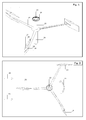
- FIG. 1 shown is an axonometric view of a planetary rotor device with 3 spokes below water level and with blade cutout. Shown is a fixed central axle 11 with rotating hub 12, the upper ring 13 of the hub being the starting gear wheel to transmit power. Shown are the spokes 14, being fixed connected to the hub, but by their design and construction relatively flexible in upwards and downwards movement, like the wings of a large airplane. This flexibility is needed to cope with the underwater movement caused by waves at the surface. These spokes are shaped with a sharp edge at one side and a hollow shape at the other side (see Fig. 29 ) to derive additional power from the current.
- connection between spoke and parallel axle 15 is at the middle of the parallel axle.
- the hinge lug 16 (see also Fig. 26 ) is specially shaped to hold the planetary axle 15 in such a position to the spoke, that the balanced floating blade 17 can position itself in full length parallel resting against the spoke, when forced so by the stream (see Fig 2 , 3, 4 ).
- the balanced floating blade is shaped with a cutout 18 to facilitate the free positioning of the blade, when as a consequence of the circular movement of the rotor the planetary axle is passing the point where the pressure of the stream will rotate the blade away from its position parallel against the spoke to a new position with minimal resistance to the current. (see Fig 3, 4 )
- FIG. 2 shown is a top view of a planetary rotor device with 3 spokes below water level and with blade cutout.
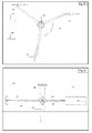
- the position of the balanced floating blades referring to the direction of the current 19 is as follows: The blade 20 most stream upwards is just in a position parallel to the spoke and by this has lost its freedom to adapt its position freely to minimize its resistance to the stream.
- the blade 17 already parallel positioned to and being pushed against the spoke by the stream receives most of the power from the current and causes the rotor to rotate counterclockwise 21 around the central axle 11 .
- the blade 22 by its freedom to adapt its position freely delivers minimal resistance to the current and is moving upwards the stream.
- FIG. 3 shown is a top view of a planetary rotor device with 3 spokes below water level and with blade cutout.
- the position of the balanced floating blades referring to the direction of the current 19 is as follows:
- the blade 20 already parallel positioned against the spoke receives most of the power from the current and causes the rotor to rotate counterclockwise 21 around the central axle 11.
- the blade 17 most stream downwards is rotating also counterclockwise 23 around the parallel axle away form its position parallel to the spoke and is turning to find a position with the least resistance to the current.
- the blade 22 delivers minimal resistance to the current and is moving upwards the stream.
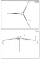
- FIG. 4 shown is a top view of a planetary rotor device with 3 spokes below water level and with blade cutout.
- This drawing is almost identical to fig. 3 , illustrating the further rotating of the blade 17 most stream downwards counterclockwise 23 around the parallel axle, turning to find a position with the least resistance to the current.
- FIG. 5 shown is a top view of a planetary rotor device with 3 spokes below water level and with blade cutout.
- the position of the balanced floating blades referring to the direction of the current 19 is as follows:
- the blade 20 already parallel positioned against the spoke receives most of the power from the current and causes the rotor to rotate counterclockwise 21 around the central axle 11.
- the blade 22 delivers minimal resistance to the current and is moving upwards the stream.
- the blade 17 most stream downwards has rotated to its position to deliver minimal resistance to the current and is also moving upwards the stream.
- the purpose of the blade cutout (see Fig 1 ) is shown as the far end of the spoke is transecting the blade 17.
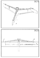
- FIG. 6 shown is a front view (looking downstream) of a planetary rotor device with 3 spokes below water level 24 and with blade cutout.
- the central rotating hub 12 resting on a bearing ring device 25 attached to the fixed central axle 11 is partly above water level making it possible to construct the most vulnerable parts like the transmission system and the electric generators on a save distance from the water level.
- the fixed central axle 11 is driven into the bottom 26.
- the balanced floating blades (17, 20, 22) are totally under water, making them less vulnerable to the forces of the waves on the surface.
- the buoyancy of the blades is adjusted in such a way that they compensate the sinking weight of the spokes and parallel axles, thus making the combination of spokes, parallel axles and blades in its totality almost weightless in their fluid surrounding.
- This adjustment also includes the right placement of ballast in the lower parts of the blades to stabilize their position as an upright stream catcher, and to avoid diagonal pressure on the parallel axles.
- FIG. 7 shown is an axonometric view of a planetary rotor device with 3 spokes below water level, having the connection between spoke and parallel axle not at the middle, but at the lower extremity 27 of the parallel axle.
- This construction gives the balanced floating blade full freedom to rotate without interference of the spoke.
- the hinge lug 28, determining the turning point of the blade around the planetary axle does not need a special shape for positioning the blade parallel to the spoke.
- An upstanding rod on the spoke is functioning as a stop rod 29 against which the blade is to be pushed by the stream in a parallel position to the spoke in order to receive most power from the current.
- the blade 30 does not need a special cutout to facilitate the free positioning of the blade. By this construction the blade can easily be lifted upwards and taken from the parallel axle when maintenance is needed.
- FIG. 8 shown is a top view of a planetary rotor device with 3 spokes below water level, having the connection between spoke and parallel axle not at the middle, but at the lower extremity of the parallel axle.
- the turning point 31 of the blade around the planetary axle is positioned on a straight line with the longitudinal axis of the spoke.
- the same explanations apply as used in reference to Fig. 2 , with the exception that the positioning of the blade parallel to the spoke is not against the spoke itself, but against the stop rod 29 upstanding from the spoke.
- This top view drawing is exemplary for most of the top views concerning the planetary rotor device variations with spokes below water level described hereafter. Therefore most of these variations will be shown only as axonometric and front views.
- FIG. 9 shown is a front view (looking downstream) of a planetary rotor device with 3 spokes below water level 24, having the hinge lug 28 connection between spoke and parallel axle not at the middle, but at the lower extremity 27 of the parallel axle. Also is shown that the positioning of the blade parallel to the spoke is not against the spoke itself, but against the stop rod upstanding from the spoke. Further the same explanations apply as used in reference to Fig. 5 .
- FIG. 10 shown is an axonometric view of a planetary rotor device with 3 spokes below water level, having the connection between spoke and parallel axle at the upper extremity 32 of the parallel axle.
- This construction gives the balanced floating blade full freedom to rotate without interference of the spoke.
- the hinge lugs 28 do not need a special shape for positioning the blade parallel to the spoke.
- a down pointing rod on the spoke is functioning as a stop rod 33 against which the blade is to be pushed by the stream in a parallel position to the spoke in order to receive most power from the current.
- the blade 30 does not need a special cutout to facilitate the free positioning of the blade. By this construction the blade can easily be sunken downwards and taken from the parallel axle when maintenance is needed.
- FIG. 11 shown is a front view (looking downstream) of a planetary rotor device with 3 spokes below water level 24, having the hing lug 28 connection between spoke and parallel axle at the upper extremity 32 of the parallel axle. This illustrates that the positioning of the blade 30 parallel to the spoke is against the stop rod pointing downwards from the spoke. Further the same explanations apply as used in reference to Fig. 5 .
- FIG. 12 shown is an axonometric view of a planetary rotor device with 3 spokes below water level, each spoke having a pair of rotating blades.
- This construction also gives the balanced floating blades full freedom to rotate without interference of the spoke.
- the hinge lugs 28 do not need a special shape for positioning the blade parallel to the spoke.
- An upstanding rod 29 and a down pointing rod 33 on the spoke are functioning as stop rods against which the blades are to be pushed by the stream in a parallel position to the spoke in order to receive most power from the current.
- the blades 34 do not need a special cutout to facilitate the free positioning of the blade. By this construction the blades can easily be lifted upwards and downwards to be taken from the parallel axle when maintenance is needed.
- FIG. 13 shown is a front view (looking downstream) of a planetary rotor device with 3 spokes below water level 24, each spoke having a pair of rotating blades,
- the hinge lug 28 connection between spoke and parallel axle is at the middle of the parallel axle. This also illustrates that the positioning of the blades 34 parallel to the spoke is against the stop rods upstanding and downward pointing from the spoke. Further the same explanations apply as used in reference to Fig. 5 .
- FIG. 14 shown is an axonometric view of a planetary rotor device with 3 pairs of spokes below water level.
- the connection between spoke and parallel axle is at both extremities 27, 32 of the parallel axle.
- the parallel axis is held by a pair of spokes 35.
- the hinge lugs 28 do not need a special shape for positioning the blade parallel to the spoke.
- a simple connecting rod 36 between the spokes is functioning as a stop rod against which the blade is to be pushed by the stream in a parallel position to the spokes in order to receive most power from the current.
- the blade 30 does not need a special cutout to facilitate the free positioning of the blade.
- This construction (3 pairs of spokes) has the advantage of greater strength, but the disadvantage of more material used.
- FIG. 15 shown is a front view (looking downstream) of a planetary rotor device with 3 pairs of spokes below water level 24. This illustrates that the positioning of the blade 30 parallel to the spoke is against the stop rod 36 between the upper spoke and lower spoke. Further the same explanations apply as used in reference to Fig. 5 .
- FIG. 16 shown is an axonometric view of a planetary rotor device with 3 spokes above water level. Shown is a fixed central axle 11 with rotating hub 37, the upper ring 13 of the hub being the starting gear wheel to transmit power. Shown are the spokes 38, illustrated here as a strong but open construction to withstand the force of waves and wind, being connected to the hub by a robust hinge construction 39, allowing vertical movement. This movement is needed to cope with different water levels (high tide, low tide) and with the influence of major waves at the surface. In this situation the connection 40 between spoke and parallel axle 15 is at the upper end of the parallel axle.
- This connection (see also Fig%) is a double hinge construction making it possible for the blade 30 to rotate around the planetary axis, but also to give it a certain degree of freedom to have its axle positioned in different vertical angles to the spoke, in order to keep the parallel position to the center axis when waves or change in water level cause the spokes to hinge vertically.
- Part of the spoke-construction is a stop rod 33 against which the blade is to be pushed by the stream in a parallel position to the spoke in order to receive most power from the current.
- FIG.17 shown is a top view of a planetary rotor device with 3 spokes above water level.
- the double hinge construction 40 holding the parallel axle is positioned in a straight line with the longitudinal axis of the spoke. Further the same explanations apply as used in reference to Fig. 2 , with the exception that the positioning of the blade parallel to the spoke is not against the spoke itself, but against the (in this figure not visible) stop rod downward pointing from the spoke.
- FIG. 18 shown is a front view (looking downstream) of a planetary rotor device with 3 spokes above water level 24. This illustrates that the positioning of the blade 30 parallel to the spoke is against the stop rod 33 downward pointing from the spoke. Further the same explanations apply as used in reference to Fig. 5 .
- FIG. 19 shown is an axonometric view of a planetary rotor device with 3 pairs of spokes where of each pair of spokes one spoke is above water level and one spoke is below water level.
- the connection between spoke and parallel axle is at both extremities of the parallel axle.
- the spokes below water level are equipped with a sliding connection (See Fig. 20 and Fig. 27 ) and the planetary axle has an extension 41, all this in order to cope with the up-and-down movements of the blades and the spokes above water level due to waves or tidal effects.
- This construction (3 pairs of spokes) has the advantage of greater strength, but the disadvantage of more material used.
- FIG. 20 shown is a front view (looking downstream) of a planetary rotor device with 3 pairs of spokes where of each pair of spokes one spoke is above water level 24 and one spoke is below water level.
- the sliding connection 42 and the parallel axle extension 41 to cope with the up-and-down movements of the blades and the spokes above water level due to waves or tidal effects. Due to the sliding connection the sinking weight of the underwater spokes cannot be compensated by the buoyancy of the blades, so these spokes themselves (by their construction or the materials used) have to be "weightless" in their fluid surrounding. Further the same explanations apply as used in reference to Fig. 5 .
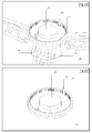
- FIG. 21 shown is an axonometric view of the starting gear wheel 13 and hinge construction 39 as a part of the central rotating hub 37 resting on a bearing ring device 25 of a planetary rotor device with spokes above water level.
- the small cogwheels and a part of their axles 43 that will transfer the rotation from the starting gear wheel to the gear unit housing (not shown here), which is mounted on the fixed central axis-pillar 11.
- FIG. 22 shown is an axonometric view of the starting gear wheel 13 as a part of the central hub 12 of a planetary rotor device with spokes under water level. This illustrates the positioning of the gear construction safely above water level. Also shown are the small cogwheels and a part of their shafts 43 that will transfer the rotation from the starting gear wheel to the gear unit housing (not shown here), which is mounted on the fixed central axis-pillar.
- FIG. 23 shown is an axonometric view of an external gear type starting gear wheel 44 being the upper part of the central hub of a planetary rotor device. This illustrates that the starting gear wheel can also be of the external gear wheel type.
- FIG. 24 shown is an axonometric view of a bevel gear type starting gear wheel 45, being the upper part of the central hub of a planetary rotor device. This illustrates that the starting gear wheel can also be of the bevel gear wheel type.
- FIG. 25 shown is a drawing of an axonometric view of the hinge-2 joint (vertical parallel axle 15 and horizontal axle 46 ) between an above water level spoke 38 and a balanced floating blade 20. This illustrates the robustness of the hinge construction.
- FIG. 26 shown is a drawing of an axonometric view of the hinge joint between a below water level spoke and a parallel axle with blade having a cutout.
- FIG. 27 shown is a drawing of an axonometric view of the hinge joint 28 between a below water level spoke 14 and a parallel axle with blade not having a cutout. This illustrates that the hinge construction is less complicated.
- FIG. 28 shown is a drawing of an axonometric view of the sliding joint 42 between a below water level spoke 14 and a parallel axle with extension 41 of a rotor with 3 pairs of spokes where of each pair of spokes one spoke is above water level and one spoke is below water level.
- the balanced floating blade is omitted. This illustrates the solution for the difference in vertical flexibility between spokes above water level and spokes below water level.
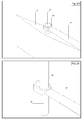
- FIG. 29 shown is a drawing of a sectional plane view 47 of a below water level spoke. This illustrates that also these spokes when rotating are contributing to produce maximum drag when encountering water flow in one direction, and either minimum drag, when encountering water flow in the opposite direction.
- FIG. 30 shown is a collection of sectional plane views of balanced floating blades (from a top view point). This is not an exhaustive collection, it only illustrates that depending on manufacturing costs, local circumstances, desired robustness and performance optimizing conditions, the shapes of the blades can be different without seriously interfering with the main principle of buoyancy adjustment and rotating properties causing maximal volume catching when encountering water flow in one direction, and either minimum volume catching, when encountering water flow in the opposite direction. Shown are symmetrical designs 48, 49, 50, 52 and asymmetrical designs 51, 53, 54. Also shown is the difference in straight-lined simple to construct designs 48, 49, 50, 51, and more complicated rounded, curved designs 52, 53, 54.
- FIG. 31 as in one embodiment of the present invention, shown is a selection of the main elements of an application of this invention, drawn separately to give better insight, also added are the main elements of a possible superstructure, which illustrates the possibility to transfer the power from the central starting gearwheel to known devices nowadays used by the windmill industry.
- Shown is the fixed central pillar 11 functioning as the central axle; the bearing ring 25 to be fixed to the central pillar to bear the construction of the rotating spoke-hub 37 and spokes 38 (here shown as the variant with 3 spokes above water level, see Fig. 16 ); the planetary axles 15 parallel to the central axle, holding the balanced floating blades 30 rotating around them and the starting gear wheel 13 being the upper part of the rotating spoke-hub.
- the possible superstructure (See Fig. 32 ) is formed by the gear unit housing 56 situated on the starting gearwheel cover 55, both to be fixed at the fixed central pillar forming a platform for the further built up 57 of this superstructure on which the nacelles 58 housing the generators are fixed.
- FIG. 32 shown is a more detailed drawing of an application of this invention with main elements separated, showing one of the possibilities to utilize it to drive a multiple set of standard windmill generators, here situated in housings (nacelles) 58 commonly used in the wind turbine field. Shown is the starting gearwheel cover 55 and the gear unit housing 56 forming a platform on which a foot 59 for the nacelles holds a belt or chain driven transmission 60 to the drive shafts of the standard windmill generators. Shown are the holes 62 for the shafts that transfer the power from the gear house to the foot of the nacelles. Also shown are the holes 61 through which the cog wheel shafts 43 transfer the rotating power from the starting gearwheel 13 to the gear house.
- FIG. 33 shown is an integrated (main elements unified) drawing of an application of this invention (in this case displayed as the variant with 3 pairs of spokes below water level. see Fig. 14 ) showing one of the possibilities to utilize it to drive a multiple set of generators, here situated in housings (nacelles) 58 commonly used in the wind turbine field. Shown is the gear unit housing 56 situated on the starting gearwheel cover 55, all fixed at the fixed central pillar 11 forming a platform for the foot 59 of the nacelles holding the transmission of the output of the gear unit housing to the generators. Also shown is the possibility of a further extension 63 of the fixed central pillar to be equipped with a standard wind-turbine 64.
Landscapes
- Engineering & Computer Science (AREA)
- Power Engineering (AREA)
- Chemical & Material Sciences (AREA)
- Combustion & Propulsion (AREA)
- Mechanical Engineering (AREA)
- General Engineering & Computer Science (AREA)
- Hydraulic Turbines (AREA)
- Other Liquid Machine Or Engine Such As Wave Power Use (AREA)
Priority Applications (2)
| Application Number | Priority Date | Filing Date | Title |
|---|---|---|---|
| EP10165597A EP2381090A3 (de) | 2010-04-25 | 2010-06-10 | Hebelwirkung maximierendes Wasserrad mit vertikale Achse |
| US13/091,149 US20120098266A1 (en) | 2010-04-25 | 2011-04-21 | Leverage-maximizing vertical axis waterwheel rotor |
Applications Claiming Priority (2)
| Application Number | Priority Date | Filing Date | Title |
|---|---|---|---|
| US32770110P | 2010-04-25 | 2010-04-25 | |
| EP10165597A EP2381090A3 (de) | 2010-04-25 | 2010-06-10 | Hebelwirkung maximierendes Wasserrad mit vertikale Achse |
Publications (2)
| Publication Number | Publication Date |
|---|---|
| EP2381090A2 true EP2381090A2 (de) | 2011-10-26 |
| EP2381090A3 EP2381090A3 (de) | 2012-10-03 |
Family
ID=42537826
Family Applications (1)
| Application Number | Title | Priority Date | Filing Date |
|---|---|---|---|
| EP10165597A Withdrawn EP2381090A3 (de) | 2010-04-25 | 2010-06-10 | Hebelwirkung maximierendes Wasserrad mit vertikale Achse |
Country Status (2)
| Country | Link |
|---|---|
| US (1) | US20120098266A1 (de) |
| EP (1) | EP2381090A3 (de) |
Cited By (6)
| Publication number | Priority date | Publication date | Assignee | Title |
|---|---|---|---|---|
| CN102979657A (zh) * | 2012-11-30 | 2013-03-20 | 蔡长运 | 利用海浪和海水流动能发电的设备 |
| FR3008742A1 (fr) * | 2013-07-19 | 2015-01-23 | Mathieu Etienne Andre Boda | Hydrolienne a pales mobiles |
| CN105604770A (zh) * | 2015-09-10 | 2016-05-25 | 徐毓艺 | 流水百叶式动力发电机 |
| DE202016003874U1 (de) | 2016-06-21 | 2016-07-26 | Schiffswerft Hermann Barthel GmbH | Vorrichtung zur Gewinnung von Strömungsenergie aus fließenden Medien mittels horizontal drehender Wasserräder, gehalten durch Schwimmkörper |
| TWI710707B (zh) * | 2019-01-31 | 2020-11-21 | 翁振國 | 動力驅動用葉輪 |
| CN113431726A (zh) * | 2021-08-03 | 2021-09-24 | 曾昭达 | 单向海流海波水平能量收集器及其能量收集系统 |
Families Citing this family (4)
| Publication number | Priority date | Publication date | Assignee | Title |
|---|---|---|---|---|
| US10941749B2 (en) * | 2015-08-28 | 2021-03-09 | Differential Dynamics Corporation | Speed converter-controlled river turbines |
| US10947956B2 (en) * | 2018-09-18 | 2021-03-16 | Differential Dynamics Corporation | Expandable power marine hydrokinetic turbines, pumps, compressors and transmissions |
| US10502178B2 (en) | 2017-03-10 | 2019-12-10 | Regents Of The University Of Minnesota | In-bank veritcal axis hydropower system |
| TWI696752B (zh) * | 2019-07-10 | 2020-06-21 | 國立臺灣師範大學 | 自動擷取流水能的方法及其裝置 |
Family Cites Families (14)
| Publication number | Priority date | Publication date | Assignee | Title |
|---|---|---|---|---|
| US1314232A (en) * | 1919-08-26 | Oottlob wtthb | ||
| US1083472A (en) * | 1912-11-19 | 1914-01-06 | Orrin W Watson | Current-wheel. |
| US1612025A (en) * | 1926-01-08 | 1926-12-28 | Jankowski Julijan | Water wheel |
| US3604942A (en) * | 1970-05-11 | 1971-09-14 | Curtis A Nelson | Underwater generator |
| US3912937A (en) * | 1973-07-20 | 1975-10-14 | Jerome M Lesser | Submarine electrical energy generating apparatus |
| US3922012A (en) * | 1974-02-28 | 1975-11-25 | Harry Herz | Power generator |
| US4038821A (en) * | 1976-02-12 | 1977-08-02 | Black Jerimiah B | Fluid current motor |
| US4368392A (en) * | 1981-06-03 | 1983-01-11 | Pinson Energy Corporation | Water turbine |
| US4545729A (en) * | 1983-07-28 | 1985-10-08 | Joe Storm | Wind turbine apparatus |
| US5844323A (en) * | 1996-08-12 | 1998-12-01 | Hung; Ming-Tung | Rotatable wheel for developing fluid kinetic energy by accepting action forces from multiple directions |
| EP1205661A1 (de) * | 2000-11-13 | 2002-05-15 | Isidro U. Ursua | Windmotor mit senkrechter Drehachse |
| CA2432458A1 (en) * | 2003-06-16 | 2004-12-16 | Henkenhaf Willi | Water wheel generator pair |
| WO2007012195A1 (en) * | 2005-07-28 | 2007-02-01 | Cleanfield Energy Corp. | Power generating system including modular wind turbine-generator assembly |
| GB0812524D0 (en) * | 2008-07-09 | 2008-08-13 | Mowat Technical & Design Servi | Water turbine |
-
2010
- 2010-06-10 EP EP10165597A patent/EP2381090A3/de not_active Withdrawn
-
2011
- 2011-04-21 US US13/091,149 patent/US20120098266A1/en not_active Abandoned
Non-Patent Citations (1)
| Title |
|---|
| None |
Cited By (6)
| Publication number | Priority date | Publication date | Assignee | Title |
|---|---|---|---|---|
| CN102979657A (zh) * | 2012-11-30 | 2013-03-20 | 蔡长运 | 利用海浪和海水流动能发电的设备 |
| FR3008742A1 (fr) * | 2013-07-19 | 2015-01-23 | Mathieu Etienne Andre Boda | Hydrolienne a pales mobiles |
| CN105604770A (zh) * | 2015-09-10 | 2016-05-25 | 徐毓艺 | 流水百叶式动力发电机 |
| DE202016003874U1 (de) | 2016-06-21 | 2016-07-26 | Schiffswerft Hermann Barthel GmbH | Vorrichtung zur Gewinnung von Strömungsenergie aus fließenden Medien mittels horizontal drehender Wasserräder, gehalten durch Schwimmkörper |
| TWI710707B (zh) * | 2019-01-31 | 2020-11-21 | 翁振國 | 動力驅動用葉輪 |
| CN113431726A (zh) * | 2021-08-03 | 2021-09-24 | 曾昭达 | 单向海流海波水平能量收集器及其能量收集系统 |
Also Published As
| Publication number | Publication date |
|---|---|
| US20120098266A1 (en) | 2012-04-26 |
| EP2381090A3 (de) | 2012-10-03 |
Similar Documents
| Publication | Publication Date | Title |
|---|---|---|
| EP2381090A2 (de) | Hebelwirkung maximierendes Wasserrad mit vertikale Achse | |
| EP2469073A2 (de) | Wasserkraftwerk mit vertikaler Achse und sich hin- und herbewegenden Schaufeln | |
| AU746011B2 (en) | Extracting power from moving water | |
| CN103328815B (zh) | 用于从流体的流动水流中产生电能的系统和方法 | |
| US7215036B1 (en) | Current power generator | |
| US9719483B2 (en) | Method and apparatus for generating energy from a flowing water current | |
| CA2779820C (en) | Hydrokinetic energy conversion system | |
| CN1143957C (zh) | 洋流发电装置 | |
| US20080012345A1 (en) | Tethered propgen | |
| CN103782026B (zh) | 用于从流动液体中提取能量的设备 | |
| US20090236858A1 (en) | Vertical turbine for water or wind power generation | |
| CN106368905B (zh) | 一种海洋风力发电装置 | |
| US10151294B2 (en) | Buoyant housing device enabling large-scale power extraction from fluid current | |
| CN104481780B (zh) | 浅浸没漂浮式带导流罩水平轴海流发电系统 | |
| US9709024B2 (en) | Vortex energy recovery turbine | |
| IE86387B1 (en) | A vertical fluid flow turbine | |
| JP2014001689A (ja) | 水流エネルギーを利用した発電装置 | |
| EP1540172B1 (de) | Vorrichtung mit einem geneigten tragepfeiler zur verankerung einer axialturbine für die erzeugung von elektrischem strom auf der grundlage von wasserströmungen | |
| GB2480000A (en) | Water turbine assembly | |
| US9284941B2 (en) | Natural energy extraction apparatus | |
| US20140138955A1 (en) | Vertical axis mooring rotor | |
| CN109519322A (zh) | 一种偏心惯性轮式发电平台 | |
| KR102427102B1 (ko) | 심해저 해류 발전기 및 심해저 해류 발전 시스템 | |
| KR20230163314A (ko) | 조류발전용 다단 나선형 돛 가변익 터빈 | |
| JP2013096264A (ja) | 発電装置 |
Legal Events
| Date | Code | Title | Description |
|---|---|---|---|
| AK | Designated contracting states |
Kind code of ref document: A2 Designated state(s): AL AT BE BG CH CY CZ DE DK EE ES FI FR GB GR HR HU IE IS IT LI LT LU LV MC MK MT NL NO PL PT RO SE SI SK SM TR |
|
| AX | Request for extension of the european patent |
Extension state: BA ME RS |
|
| PUAI | Public reference made under article 153(3) epc to a published international application that has entered the european phase |
Free format text: ORIGINAL CODE: 0009012 |
|
| PUAL | Search report despatched |
Free format text: ORIGINAL CODE: 0009013 |
|
| AK | Designated contracting states |
Kind code of ref document: A3 Designated state(s): AL AT BE BG CH CY CZ DE DK EE ES FI FR GB GR HR HU IE IS IT LI LT LU LV MC MK MT NL NO PL PT RO SE SI SK SM TR |
|
| AX | Request for extension of the european patent |
Extension state: BA ME RS |
|
| RIC1 | Information provided on ipc code assigned before grant |
Ipc: F03B 17/06 20060101AFI20120828BHEP |
|
| STAA | Information on the status of an ep patent application or granted ep patent |
Free format text: STATUS: THE APPLICATION IS DEEMED TO BE WITHDRAWN |
|
| 18D | Application deemed to be withdrawn |
Effective date: 20120404 |