EP2381186A1 - Élément de support de serpentin - Google Patents
Élément de support de serpentin Download PDFInfo
- Publication number
- EP2381186A1 EP2381186A1 EP10784939A EP10784939A EP2381186A1 EP 2381186 A1 EP2381186 A1 EP 2381186A1 EP 10784939 A EP10784939 A EP 10784939A EP 10784939 A EP10784939 A EP 10784939A EP 2381186 A1 EP2381186 A1 EP 2381186A1
- Authority
- EP
- European Patent Office
- Prior art keywords
- coil
- support member
- portions
- coil support
- engagement portions
- Prior art date
- Legal status (The legal status is an assumption and is not a legal conclusion. Google has not performed a legal analysis and makes no representation as to the accuracy of the status listed.)
- Granted
Links
Images





Classifications
-
- F—MECHANICAL ENGINEERING; LIGHTING; HEATING; WEAPONS; BLASTING
- F24—HEATING; RANGES; VENTILATING
- F24H—FLUID HEATERS, e.g. WATER OR AIR HEATERS, HAVING HEAT-GENERATING MEANS, e.g. HEAT PUMPS, IN GENERAL
- F24H1/00—Water heaters, e.g. boilers, continuous-flow heaters or water-storage heaters
- F24H1/18—Water-storage heaters
- F24H1/20—Water-storage heaters with immersed heating elements, e.g. electric elements or furnace tubes
- F24H1/208—Water-storage heaters with immersed heating elements, e.g. electric elements or furnace tubes with tubes filled with heat transfer fluid
-
- F—MECHANICAL ENGINEERING; LIGHTING; HEATING; WEAPONS; BLASTING
- F24—HEATING; RANGES; VENTILATING
- F24H—FLUID HEATERS, e.g. WATER OR AIR HEATERS, HAVING HEAT-GENERATING MEANS, e.g. HEAT PUMPS, IN GENERAL
- F24H9/00—Details
- F24H9/18—Arrangement or mounting of grates or heating means
- F24H9/1809—Arrangement or mounting of grates or heating means for water heaters
- F24H9/1832—Arrangement or mounting of combustion heating means, e.g. grates or burners
-
- F—MECHANICAL ENGINEERING; LIGHTING; HEATING; WEAPONS; BLASTING
- F28—HEAT EXCHANGE IN GENERAL
- F28D—HEAT-EXCHANGE APPARATUS, NOT PROVIDED FOR IN ANOTHER SUBCLASS, IN WHICH THE HEAT-EXCHANGE MEDIA DO NOT COME INTO DIRECT CONTACT
- F28D1/00—Heat-exchange apparatus having stationary conduit assemblies for one heat-exchange medium only, the media being in contact with different sides of the conduit wall, in which the other heat-exchange medium is a large body of fluid, e.g. domestic or motor car radiators
- F28D1/02—Heat-exchange apparatus having stationary conduit assemblies for one heat-exchange medium only, the media being in contact with different sides of the conduit wall, in which the other heat-exchange medium is a large body of fluid, e.g. domestic or motor car radiators with heat-exchange conduits immersed in the body of fluid
- F28D1/04—Heat-exchange apparatus having stationary conduit assemblies for one heat-exchange medium only, the media being in contact with different sides of the conduit wall, in which the other heat-exchange medium is a large body of fluid, e.g. domestic or motor car radiators with heat-exchange conduits immersed in the body of fluid with tubular conduits
- F28D1/047—Heat-exchange apparatus having stationary conduit assemblies for one heat-exchange medium only, the media being in contact with different sides of the conduit wall, in which the other heat-exchange medium is a large body of fluid, e.g. domestic or motor car radiators with heat-exchange conduits immersed in the body of fluid with tubular conduits the conduits being bent, e.g. in a serpentine or zig-zag
- F28D1/0472—Heat-exchange apparatus having stationary conduit assemblies for one heat-exchange medium only, the media being in contact with different sides of the conduit wall, in which the other heat-exchange medium is a large body of fluid, e.g. domestic or motor car radiators with heat-exchange conduits immersed in the body of fluid with tubular conduits the conduits being bent, e.g. in a serpentine or zig-zag the conduits being helically or spirally coiled
-
- F—MECHANICAL ENGINEERING; LIGHTING; HEATING; WEAPONS; BLASTING
- F28—HEAT EXCHANGE IN GENERAL
- F28D—HEAT-EXCHANGE APPARATUS, NOT PROVIDED FOR IN ANOTHER SUBCLASS, IN WHICH THE HEAT-EXCHANGE MEDIA DO NOT COME INTO DIRECT CONTACT
- F28D20/00—Heat storage plants or apparatus in general; Regenerative heat-exchange apparatus not covered by groups F28D17/00 or F28D19/00
- F28D20/0034—Heat storage plants or apparatus in general; Regenerative heat-exchange apparatus not covered by groups F28D17/00 or F28D19/00 using liquid heat storage material
-
- F—MECHANICAL ENGINEERING; LIGHTING; HEATING; WEAPONS; BLASTING
- F28—HEAT EXCHANGE IN GENERAL
- F28F—DETAILS OF HEAT-EXCHANGE AND HEAT-TRANSFER APPARATUS, OF GENERAL APPLICATION
- F28F9/00—Casings; Header boxes; Auxiliary supports for elements; Auxiliary members within casings
- F28F9/007—Auxiliary supports for elements
- F28F9/013—Auxiliary supports for elements for tubes or tube-assemblies
- F28F9/0131—Auxiliary supports for elements for tubes or tube-assemblies formed by plates
-
- F—MECHANICAL ENGINEERING; LIGHTING; HEATING; WEAPONS; BLASTING
- F28—HEAT EXCHANGE IN GENERAL
- F28D—HEAT-EXCHANGE APPARATUS, NOT PROVIDED FOR IN ANOTHER SUBCLASS, IN WHICH THE HEAT-EXCHANGE MEDIA DO NOT COME INTO DIRECT CONTACT
- F28D20/00—Heat storage plants or apparatus in general; Regenerative heat-exchange apparatus not covered by groups F28D17/00 or F28D19/00
- F28D2020/0065—Details, e.g. particular heat storage tanks, auxiliary members within tanks
- F28D2020/0078—Heat exchanger arrangements
-
- Y—GENERAL TAGGING OF NEW TECHNOLOGICAL DEVELOPMENTS; GENERAL TAGGING OF CROSS-SECTIONAL TECHNOLOGIES SPANNING OVER SEVERAL SECTIONS OF THE IPC; TECHNICAL SUBJECTS COVERED BY FORMER USPC CROSS-REFERENCE ART COLLECTIONS [XRACs] AND DIGESTS
- Y02—TECHNOLOGIES OR APPLICATIONS FOR MITIGATION OR ADAPTATION AGAINST CLIMATE CHANGE
- Y02E—REDUCTION OF GREENHOUSE GAS [GHG] EMISSIONS, RELATED TO ENERGY GENERATION, TRANSMISSION OR DISTRIBUTION
- Y02E60/00—Enabling technologies; Technologies with a potential or indirect contribution to GHG emissions mitigation
- Y02E60/14—Thermal energy storage
Definitions
- the present invention relates to a coil support member for a coil configured by a coiled tube placed in a water storage vessel.
- a coil support member pertaining to a first aspect of the present invention is a coil support member that is attached to a coil configured by a coiled tube placed inside a water storage vessel and which, because of multiple openings formed so as to be arranged in a line in a lengthwise direction and sites surrounding the openings, prevents contact between mutually adjacent loops of the tube of the coil and suppresses contact between an inner peripheral surface of the water storage vessel and an outer peripheral surface of the coil, the coil support member comprising insertion portions and a non-insertion portion.
- the insertion portions are formed between the openings that are mutually adjacent, and the insertion portions are inserted into an intra-coil space located further inward in a radial direction than the outer peripheral surface of the coil when the coil support member is attached to the coil.
- the non-insertion portion is positioned in an extra-coil space located further outward in the radial direction than the outer peripheral surface of the coil when the coil support member is attached to the coil. Further, the insertion portions have insertion body portions and engagement portions. The insertion body portions prevent contact between mutually adjacent loops of the tube. The engagement portions project from the insertion body portions, contact the tube from the intra-coil space, and maintain the inserted state of the insertion body portions.
- a coil support member pertaining to a second aspect of the present invention is the coil support member pertaining to the first aspect, wherein distal end portions of the engagement portions and joint portions between the engagement portions and the insertion body portions are shaped in arc shapes.
- the distal end portions of the engagement portions have arc shapes, so it becomes easier for the distal end portions of the engagement portions and the surface of the tube to slide against each other, and it becomes easier for the insertion body portions to enter the clearances between the mutually adjacent loops of the tube. Further, when the engagement portions bend, stress concentrates in the joint portions, but because the joint portions are shaped in arc shapes, the stress is suppressed from concentrating in one point and damage to the joint portions is prevented.
- a coil support member pertaining to a third aspect of the present invention is the coil support member pertaining to the first aspect, wherein the engagement portions include first engagement portions that project from one of the insertion body portions towards one side of the openings that are adjacent to both sides of that one insertion body portion and second engagement portions that project towards the other side.
- the insertion body portions twist as a result of the sides having the engagement portions being pressed by the tube, and it becomes easier for the coil support member to become disengaged from the tube because the engagement portions slant when the insertion body portions have been twisted in one direction.
- twisting in one direction is prevented because there is one more engagement portion on the opposite side, so it becomes difficult for the coil support member to become disengaged from the tube.
- a coil support member pertaining to a fourth aspect of the present invention is the coil support member pertaining to the third aspect, wherein the first engagement portions and the second engagement portions are positioned a predetermined distance apart from each other in a direction orthogonal to the direction in which the openings are arranged in a line.
- the two sets of engagement portions bend at the same time when the insertion portions are inserted into the coil, so the insertion force becomes larger.
- the first engagement portions and the second engagement portions are positioned the predetermined distance apart from each other, so it becomes possible to insert the insertion portions such that one set of the engagement portions bends first and the other set of the engagement portions bends later. As a result, the peak of the insertion force can be lowered, and, correspondingly, insertion becomes easier.
- a coil support member pertaining to a fifth aspect of the present invention is the coil support member pertaining to the first aspect, wherein the non-insertion portion, the insertion body portions, and the engagement portions are integrally molded.
- the number of parts is reduced, and the coil support member can be manufactured by any of the methods of milling, punch molding, and injection molding, so a reasonable manufacturing method can be selected depending on the production quantity.
- a coil support member pertaining to a sixth aspect of the present invention is the coil support member pertaining to the fifth aspect, wherein the coil support member is molded out of high-density polyethylene.
- high-density polyethylene resin is lightweight and has a moderate degree of elasticity. Further, high-density polyethylene has no adverse effects with respect to drinking water and food, is also resistant to high-temperature water for hot-water supply, and is suited to prolonged immersion in water.
- a water storage vessel assembly pertaining to a seventh aspect of the present invention comprises the coil support member pertaining to any one of the first aspect to the sixth aspect, the coil, and the water storage vessel.
- a water storage vessel assembly pertaining to an eighth aspect of the present invention is the water storage vessel assembly pertaining to the seventh aspect, wherein in the non-insertion portion of the coil support member, first slanted portions and second slanted portions are formed.
- the first slanted portions slant in a direction in which the width of the non-insertion portion becomes narrower nearer a lengthwise direction end surface.
- the second slanted portions slant in the direction in which the width of the non-insertion portion becomes narrower from positions nearer the end surface than the first slanted portions to the end surface.
- the non-insertion portion of the coil support member by allowing the non-insertion portion of the coil support member to slant towards the end surface such that the width of the non-insertion portion becomes narrower, at the initial stage of incorporation, the bending amount becomes smaller and shaving is suppressed. Further, after the coil support member has been incorporated a certain extent, the portion that has not yet been incorporated also bends by itself after the bending of the portion that has been incorporated first, so incorporation becomes easier.
- the bottom portion of a vessel has a "bowl-like shape" where its diameter becomes smaller towards its center, but because the width of the end portion of the non-insertion portion is tapered because of the second slanted portions, bending of the kind where stress concentrates on one side of the end portion is suppressed, and the coil support member can withstand prolonged use.
- a water storage vessel assembly pertaining to a ninth aspect of the present invention is the water storage vessel assembly pertaining to the seventh aspect or the eighth aspect, wherein a force P1 needed for applying, to free ends of the non-insertion portion, bending equivalent to a dimensional difference S - R between an inner peripheral surface radius R of the water storage vessel and a hypothetical shortest dimension S of the coil is less than 100 N.
- the hypothetical shortest dimension S is a dimension interconnecting in a shortest manner the central axis of the coil and the width direction free ends of the non-insertion portion of the coil support member as attached to that coil,
- the engagement portions deter the movement of the coil support member, so the coil support member is prevented from becoming disengaged from the tube.
- the coil support member pertaining to the second aspect of the present invention it becomes easier for the distal end portions of the engagement portions and the surface of the tube to slide against each other, and it becomes easier for the insertion body portions to enter the clearances between the mutually adjacent loops of the tube. Further, because the joint portions are shaped in arc shapes, stress is suppressed from concentrating in one point and damage to the joint portions is prevented.
- the first engagement portions and the second engagement portions are positioned the predetermined distance apart from each other, so it becomes possible to insert the insertion portions such that one set of the engagement portions bends first and the other set of the engagement portions bends later, the peak of the insertion force can be lowered, and, correspondingly, insertion becomes easier.
- the number of parts is reduced, and the coil support member can be manufactured by any of the methods of milling, punch molding, and injection molding, so a reasonable manufacturing method can be selected depending on the production quantity.
- high-density polyethylene resin is lightweight and has a moderate degree of elasticity. Further, high-density polyethylene resin has no adverse effects with respect to drinking water and food, is also resistant to high-temperature water for hot-water supply, and is suited to prolonged immersion in water.
- the engagement portions deter the movement of the coil support member, so the coil support member is prevented from becoming disengaged from the tube.
- the bending amount becomes smaller, so shaving is suppressed.
- the portion that has not yet been incorporated bends by itself after the bending of the portion that has been incorporated first, so incorporation becomes easier.
- the width of the end portion of the non-insertion portion is tapered, bending of the kind where stress concentrates on one side of the end portion is suppressed, and the coil support member can withstand prolonged use.
- the work of the worker incorporating the coil into the water storage vessel while bending the coil support member becomes easier.
- FIG 1 is a front view of a water storage vessel assembly equipped with a coil support member pertaining to one embodiment of the present invention.
- a water storage vessel assembly 3 is used as a vessel that stores hot water of a hot water storage-type water heater and is equipped with a water storage vessel 30 and a coil 4 that is placed inside the water storage vessel 30.
- the water storage vessel 30 is a cylindrical vessel made of stainless steel, and its top portion and its bottom portion are formed in bowl-like shapes.
- the coil 4 is one type of heat exchanger configured by a tube 40 that is coiled in the shape of a cylindrical helix; in the present embodiment, the tube 40 is a tube made of stainless steel whose corrosion resistance and heat resistance are high, and high-temperature hot water circulates inside the tube 40.
- the water inside the water storage vessel 30 can be heated to about 80°C by heat exchange with the coil 4.
- the tube 40 of the coil 4 is connected to a heat pump unit (not shown) installed outside the water storage vessel assembly 3, and the high-temperature hot water circulating through the coil 4 is heated by the heat pump unit.
- the heating principle resulting from the heat pump unit is a well-known technology and is also introduced in patent citation 1, so description will be omitted here.
- FIG 2 is a sectional view of the water storage vessel assembly along line A-A of FIG 1 .
- coil support members 10 are attached to the coil 4 such that a clearance is ensured between the outer peripheral surface of the coil 4 and the inner peripheral surface of the water storage vessel 30.
- Three of the coil support members 10 are placed on the coil 4 at 120° intervals with respect to the center of the coil 4.
- FIG 3 is a perspective view of the coil to which the coil support members are attached.
- the coil support members 10 prevent contact between mutually adjacent loops of the tube 40 of the coil 4 and suppress contact between the inner peripheral surface of the water storage vessel 30 and the outer peripheral surface of the coil 4.
- the outer peripheral surface of the coil 4 is, as shown in FIG 2 , a virtual surface configured by extending, in the lengthwise direction of the coil 4, the line of the outermost perimeter of the tube 40 when seen in a plan view.
- the outer peripheral surface of the coil 4 is a virtual cylindrical surface SFo having the helix outer diameter of the helical coil 4.
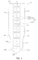
- FIG. 4 is a front view of the coil support member.
- FIG. 3 and FIG. 4 not only is the function of simply preventing contact between the mutually adjacent loops of the tube 40 of the coil 4 required of the coil support member 10, but also the function of maintaining the clearances between the mutually adjacent loops of the tube 40 in a constant range; in order to realize these functions, multiple openings 11 formed so as to be arranged in a line an interval apart from each other in the lengthwise direction are disposed in the coil support member 10.
- the openings 11 are elongate holes, and their lengthwise direction is perpendicular to the lengthwise direction of the coil support member 10.
- the corners of the openings 11 are shaped in arc shapes.
- the coil support member 10 comprises insertion portions 12 and a non-insertion portion 13.
- the insertion portions 12 are formed between the openings 11 that are mutually adjacent, and the insertion portions 12 are inserted into an intra-coil space located further inward in the radial direction than the outer peripheral surface of the coil 4 when the coil support member 10 is attached to the coil 4.
- the insertion portions 12 have insertion body portions 121 and engagements portion 122.
- the insertion body portions 121 maintain the clearances between the mutually adjacent loops of the tube 40 at a substantial constant.
- the engagement portions 122 project from the insertion body portions 121, contact the tube 40 from the intra-coil space, and maintain the inserted state of the insertion body portions 121.
- the engagement portions 122 include first engagement portions 122a and second engagement portions 122b. As shown in FIG 4 , in a state before the coil support member 10 is attached to the coil 4, the first engagement portions 122a project from one of the insertion body portions 121 towards the opening 11 on the upper side of the openings that are adj acent to both the upper and lower sides of that one insertion body portion, and the second engagement portion 122b project towards the opening 11 an the lower side. That is, the directions in which the first engagement portions 122a and the second engagement portions 122b project are substantially parallel to the lengthwise direction of the coil support member it.
- the engagement portions 122 may also comprise just either one of the first engagement portions 122a and the second engagement portions 122b; however, in that case, it is necessary to note that it becomes easier for the sides of the insertion body portions 121 having either one of the first engagement portions 122a and the second engagement portions 122b to be pressed by the tube 40 and twist in one direction. Consequently, having one more engagement portion on the opposite side prevents twisting in one direction, so there is the effect that it becomes even more difficult for the coil support member 10 to become disengaged from the tube 40.
- this will be taken to describe matters common to the first engagement portions 122a and the second engagement portions 122b.
- the worker When an assembly worker attaches the coil support member 10 to the coil 4, the worker places the insertion body portions 121 into the clearances between the mutually adjacent loops of the tube 40. At this time, the engagement portions 122 contact the tube 40, move through the clearances while bending, and eventually confront the tube 40 from the intra-coil space.
- the distal end portions of the engagement portions 122 are shaped in arc shapes, so it becomes easier for the distal end portions of the engagement portions 122 and the surface of the tube 40 to slide against each other; as a result, it becomes easier for the insertion body portions 121 to enter the clearances between the mutually adjacent loops of the tube 40. Further, when the engagement portions 122 bend, stress concentrates in the joint portions between the engagement portions 122 and the insertion body portions 121, but because the joint portions are also shaped in arc shapes, the stress is suppressed from concentrating in one point. As a result, damage to the joint portions is prevented.
- FIG. 5 is a partial sectional view of the coil and the coil support member along line B-B of FIG 2 .
- the first engagement portions 122a project from one of the insertion body portions 121 towards the opening 11 on the upper side of the openings 11 that are adjacent to both the upper and lower sides of that one insertion body portion, and the direction in which the first engagement portions 122a project is parallel to the lengthwise direction of the coil 4.
- the second engagement portions 122b project towards the opening 11 on the lower side and, like the first engagement portions 122a, are parallel to the lengthwise direction of the coil 4.
- the first engagement portions 122a and the second engagement portions 122b deter the movement of the coil support member 10, so the coil support member 10 cannot become disengaged from the tube 40.
- the non-insertion portion 13 is positioned in an extra-coil space located further outward in the radial direction than the outer peripheral surface of the coil 4 when the coil support member 10 is attached to the coil 4, and the non-insertion portion 13 suppresses contact between the inner peripheral surface of the water storage vessel 30 and the outer peripheral surface of the coil 4.
- both ends (width direction free ends) of the non-insertion portion 11 are brought into contact with the inner peripheral surface of the water storage vessel 30, and when the assembly has been shaken by vibration or the like such that the outer peripheral surface of the coil 4 comes close to the inner peripheral surface of the water storage vessel 30, both ends of the non-insertion portion 13 bend and push back against the inner peripheral surface of the water storage vessel 30. Therefore, hitting of the kind where the inner peripheral surface of the water storage vessel 3 0 and the outer peripheral surface of the coil 4 collide with each other is prevented.
- the outline of the non-insertion portion 13 is, when seen in the front view of FIG 4 , formed by an upper side end 13a, right and left ends 13c, right and left first slanted portions 131, right and left ends 13d, right and left second slanted portions 132, and a lower side end 13b.
- the first slanted portions 131 slant in a direction in which the width of the non-insertion portion 13 becomes narrower nearer the lower side end 13b when seen in the front view of FIG. 4 .
- the lower side end when seen in the front view of FIG. 4 will be called "the first-in end 13b".
- the second slanted portions 132 slant in the direction in which the width of the non-insertion portion 13 becomes narrower from positions nearer the first-in end 13b than the first slanted portions 131 that is, from the endpoints of the right and left ends 13d-to the first-in end 13b.
- the non-insertion portion 13 slants such that the width of the non-insertion portion 13 on the first-in end 13b side becomes narrower towards the first-in end 13b, the bending amount at the initial stage of incorporation is small and shaving is suppressed. Further, after the coil support member has been incorporated a certain extent, the portion that has not yet been incorporated also bends by itself after the bending of the portion that has been incorporated first, so incorporation becomes easier.
- S shown in FIG. 3 is a hypothetical shortest dimension interconnecting in a shortest manner the central axis of the coil 4 and the width direction ends (the right and left ends when seen in the front view of FIG 4 ) 13c of the non-insertion portion 13 of the coil support member 10 as attached to that coil 4.
- P1 denotes a force needed for applying
- P1 is set such that P1 ⁇ 100 N. This is a condition that can facilitate the work of incorporating the coil 4 into the water storage vessel 30 while bending the coil support member 10 when the worker incorporates the coil 4 into the water storage vessel 30 and is confirmed by the following simulations.
- the free ends (the right and left ends 13c when seen in the front view of FIG. 4 ) of the non-insertion portion 13 are placed in a state where they are always pressed by the inner peripheral surface of the water storage vessel 30.
- the bottom portion of the water storage vessel 30 is formed in a "bowl-like shape" where its diameter becomes smaller towards its center, ordinarily bending would become larger.
- the non-insertion portion 13 is tapered towards the first-in end 13b because of the second slanted portions 132, bending of the kind where stress concentrates on one side of the end portion is suppressed, and the coil support member can withstand prolonged use.
- all of the sites of the coil support member 10, such as the non-insertion portion 13, the insertion body portions 121, the first engagement portions 122a, and the second engagement portions 122b, are integrally molded out of high-density polyethylene resin, so the number of parts is reduced, and the coil support member 10 can be manufactured by any of the methods of milling, punch molding, and injection molding.
- the corners of the openings 11 are set in arc shapes beforehand such that they can adapt to a milling tool blade. Therefore, a reasonable manufacturing method can be selected depending on the production quantity.
- high-density polyethylene resin which is the material, is lightweight and has a moderate degree of elasticity. Further, high-density polyethylene resin has no adverse effects on drinking water and food, is also resistant to high-temperature water for hot-water supply, and is suited to prolonged immersion in water.
- an engagement portion pressing force D is a pressing force needed to bend one of the engagement portions 122 when the insertion portions 12 of the coil support member 10 are inserted into the coil 4 and a non-insertion pressing force P (e.g., see FIG. 6B ) is a pressing force needed for holding until the width direction ends 13c of the non-insertion portion 13 of the coil support member 10 hit the outer peripheral surface of the coil 4, then the clearance between the inner peripheral surface of the water storage vessel 30 and the outer peripheral surface of the coil 4, the height dimension of the coil 4, the positions of the engagement portions 122, the material of the non-insertion portion 13, and the thickness dimension of the non-insertion portion 13 must be selected such that the relationship expression of P ⁇ N ⁇ D always holds true between a total number N of the engagement portions 122 of the coil support member 10, the engagement portion pressing force D, and the non-insertion portion pressing force P.
- selection also includes the act of reselecting while confirming whether or not the relationship of P ⁇ N ⁇ D is satisfied after an engagement portion pressing force D and the non
- the first engagement portions 122a and the second engagement portions 122b contact the tube 40. move through the clearances while bending, and eventually confront the tube 40 from the intra-coil space. Even if the coil support member 10 tries to move in a direction away from the tube 40, the first engagement portions 122a and the second engagement portions 122b deter the movement of the coil support member 10, so the coil support member 10 is prevented from becoming disengaged from the tube 40.
- the distal end portions of the first engagement portions 122a and the second engagement portions 122b have arc shapes, so it becomes easier for the distal end portions of the first engagement portions 122a and the second engagement portions 122b and the surface of the tube 40 to slide against each other, and it becomes easier for the insertion body portions 121 to enter the clearances between the mutually adjacent loops of the tube 40. Further, when the first engagement portions 122a and the second engagement portions 122b bend, stress concentrates in the joint portions, but because the joint portions are shaped in arc shapes, the stress is suppressed from concentrating in one point and damage to the joint portions is prevented.
- the non-insertion portion 13, the insertion body portions 121, the first engagement portions 122a, and the second engagement portions 122b are integrally molded out of high-density polyethylene resin, so not only is the number of parts reduced, but the coil support member 10 can be manufactured by any of the methods of milling, punch molding, and injection molding. Therefore, a reasonable manufacturing method can be selected depending on the production quantity. Further, it is difficult for the coil support member to damage the tube because high-density polyethylene resin is lightweight and has a moderate amount of elasticity; moreover, high-density polyethylene resin has no adverse effects with respect to drinking water and food, is also resistant to high-temperature water for hot-water supply, and is suited to prolonged immersion in water.
- the slanted portions 131 that allow the non-insertion portion 13 to slant towards the first-in end 13b such that the width of the non-insertion portion 13 becomes narrower are formed on the coil support member 10, whereby, at the initial stage of incorporation, the bending amount becomes small and shaving is suppressed.
- the first-in end 13b of the non-insertion portion 13 is tapered because of the second slanted portions 132, so bending of the kind where stress concentrates on one side of the end portion is suppressed, and the coil support member can withstand prolonged use.
- the force P1 needed to bend the non-insertion portion 13 is set to be less than 100 N, so the work of the worker incorporating the coil 4 into the water storage vessel while bending the coil support member 10 becomes easier.
- the clearance between the inner peripheral surface of the water storage vessel 30 and the outer peripheral surface of the coil 4, the height dimension of the coil 4, the positions of the engagement portions 122, the material of the non-insertion portion 13, and the thickness dimension of the non-insertion portion 13 are selected on the condition that the relational expression of P ⁇ N ⁇ D always holds true between the total number N of the engagement portions 122 of the coil support member 10, the engagement portion pressing force D, and the non-insertion portion pressing force P. Therefore, even when the force acting on the non-insertion portion 13 acts on all of the engagement portions 122 as a reaction force, the force required to bend all of the engagement portions 122 is larger, so the coil support member 10 is prevented from becoming disengaged from the tube.
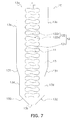
- FIG. 7 is a front view of a coil support member pertaining to a first modification of the present embodiment. In FIG. 7 , only the shape of the engagement portions of FIG. 4 is changed, so reference signs that are identical to the reference signs used in FIG. 4 will be used for portions other than the first engagement portions and the second engagement portions, and description will be omitted.
- the engagement portions 122 include first engagement portions 122r and second engagement portions 122s.
- the first engagement portions 122r project from one of the insertion body portions 121 towards the opening 11 on the upper side of the openings 11 that are adjacent to both the upper and lower sides of that one insertion body portion 121, and the second engagement portions 122s project towards the opening 11 on the lower side.
- Both the first engagement portions 122r and the second engagement portions 122s have so-called mountain shapes where the widths of the joints to the insertion body portions 121 are longer than the heights to the distal ends.
- the opening areas of the openings 11 are smaller as compared to the openings in the embodiment described above, but in both the first, engagement portions 122r and the second engagement portions 122s, the slanted surfaces interconnecting the tops and the joints to the insertion body portions 121 become gentle, and it becomes easier for the insertion body portions 121 to enter the clearances between the mutually adjacent loops of the tube 40.
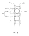
- FIG. 8 is a partial sectional view of a coil and a coil support member pertaining to a second modification.
- first engagement portions 122u project diagonally upward from between mutually adjacent loops of the tube 40 towards the vicinity of an inner peripheral surface SFi of the coil 4.
- second engagement portions 122v project diagonally downward from between mutually adjacent loops of the tube 40 towards the vicinity of the inner peripheral surface SFi of the coil 4.
- FIG. 9 is a partial sectional view of a coil and a coil support member pertaining to a third modification.
- first engagement portions 122x project diagonally upward towards the inner peripheral surface SFi from further inward of the inner peripheral surface SFi of the coil 4.
- second engagement portions 122y project diagonally downward towards the inner peripheral surface SFi from further inward of the inner peripheral surface SFi of the coil 4.
- the clearances between the mutually adjacent loops of the tube 40 of the coil 4 are stabilized and contact between the outer peripheral surface of the coil 4 and the inner peripheral surface of the water storage vessel 30 is also suppressed by the coil support member 10, so the invention is useful not just in water heaters but in devices where a coil heat exchanger with a coiled tube is placed inside a vessel.
Landscapes
- Engineering & Computer Science (AREA)
- Physics & Mathematics (AREA)
- Thermal Sciences (AREA)
- Mechanical Engineering (AREA)
- General Engineering & Computer Science (AREA)
- Chemical & Material Sciences (AREA)
- Combustion & Propulsion (AREA)
- Heat-Exchange Devices With Radiators And Conduit Assemblies (AREA)
Applications Claiming Priority (1)
| Application Number | Priority Date | Filing Date | Title |
|---|---|---|---|
| PCT/JP2010/001342 WO2011104766A1 (fr) | 2010-02-26 | 2010-02-26 | Élément de support de serpentin |
Publications (4)
| Publication Number | Publication Date |
|---|---|
| EP2381186A1 true EP2381186A1 (fr) | 2011-10-26 |
| EP2381186A4 EP2381186A4 (fr) | 2012-01-04 |
| EP2381186B1 EP2381186B1 (fr) | 2016-02-24 |
| EP2381186B8 EP2381186B8 (fr) | 2016-04-13 |
Family
ID=44506216
Family Applications (1)
| Application Number | Title | Priority Date | Filing Date |
|---|---|---|---|
| EP10784939.0A Not-in-force EP2381186B8 (fr) | 2010-02-26 | 2010-02-26 | Élément de support de serpentin |
Country Status (5)
| Country | Link |
|---|---|
| US (1) | US9702587B2 (fr) |
| EP (1) | EP2381186B8 (fr) |
| CN (1) | CN102762930B (fr) |
| AU (1) | AU2010346932B8 (fr) |
| WO (1) | WO2011104766A1 (fr) |
Cited By (3)
| Publication number | Priority date | Publication date | Assignee | Title |
|---|---|---|---|---|
| EP2899485A1 (fr) * | 2014-01-23 | 2015-07-29 | Rolls-Royce plc | Support d'échangeur de chaleur |
| NO20210187A1 (en) * | 2021-02-12 | 2022-08-15 | Energynest As | Element for a thermal energy storage, a thermal energy storage with the element and use of the element |
| EP3998432A4 (fr) * | 2019-07-16 | 2023-08-30 | Daikin Industries, Ltd. | Unité réservoir de stockage |
Families Citing this family (7)
| Publication number | Priority date | Publication date | Assignee | Title |
|---|---|---|---|---|
| US9897385B2 (en) | 2015-02-20 | 2018-02-20 | Therma-Stor LLC | Helical coil heating apparatus and method of operation |
| CN105444607A (zh) * | 2015-12-29 | 2016-03-30 | 中山日创电器有限公司 | 一种热交换管的固定结构 |
| DE102016005838A1 (de) * | 2016-05-12 | 2017-11-16 | Linde Aktiengesellschaft | Gewickelter Wärmeübertrager mit Einbauten zwischen Hemd und letzter Rohrlage |
| CN106247841B (zh) * | 2016-08-10 | 2018-11-27 | 北京华福工程有限公司 | 专用于立式设备内盘管的速装支架 |
| CN110087354B (zh) * | 2018-01-26 | 2022-05-03 | 鸿成国际科技股份有限公司 | 一种加热器支撑装置 |
| CN212658085U (zh) * | 2020-06-18 | 2021-03-05 | 浙江盾安热工科技有限公司 | 换热器 |
| US12416449B2 (en) * | 2021-11-18 | 2025-09-16 | Mahle International Gmbh | Folded coil tube spacer |
Family Cites Families (13)
| Publication number | Priority date | Publication date | Assignee | Title |
|---|---|---|---|---|
| DE1454702A1 (de) * | 1962-10-08 | 1969-03-27 | Omnical Ges Fuer Kessel Und Ap | Lagerung und Halterung von Rohrspiralen in Warmwasser-Durchflussboilern |
| CA950703A (en) * | 1970-04-03 | 1974-07-09 | Manuel C. Sanz | Automatic test tube transporter and sample dispenser |
| US4492851A (en) * | 1980-12-29 | 1985-01-08 | Brazeway, Inc. | Swap action arrangement mounting an electric defroster heater to a finned refrigeration unit |
| DD246159A1 (de) | 1986-02-17 | 1987-05-27 | Bau Und Montagekomb Erfurt Kb | Abstandshalter fuer schraubenfoermige rohrwindungen in waermeuebertragern |
| USD316038S (en) * | 1988-09-06 | 1991-04-09 | Gagnet Roland J | Slip clip for closing bags |
| US5485879A (en) | 1993-06-29 | 1996-01-23 | Bradford White Corporation | Combined water heater and heat exchanger |
| FR2709174B1 (fr) * | 1993-08-20 | 1995-11-17 | Framatome Sa | Echangeur de chaleur comportant des moyens de maintien de barres antivibratoires intercalés entre les tubes du faisceau de l'échangeur. |
| AU2003901610A0 (en) * | 2003-03-28 | 2003-05-01 | Siddons Stevens Developments Pty Ltd | Water heater/cooler |
| EP1631771A4 (fr) * | 2003-03-28 | 2011-06-01 | Siddons Stevens Developments Pty Ltd | Chauffe-eau/refroidisseur d'eau |
| DE20314766U1 (de) | 2003-09-22 | 2003-12-11 | Witzenmann Gmbh | Haltevorrichtung für wendelförmige Leitungselemente |
| SE528862C2 (sv) * | 2004-09-29 | 2007-02-27 | Thermia Vaerme Ab | Värmeväxlaranordning |
| ES2536445T3 (es) * | 2005-03-15 | 2015-05-25 | Vaillant Gmbh | Intercambiador de calor |
| DE202006004396U1 (de) | 2006-03-17 | 2007-05-10 | Viessmann Werke Gmbh & Co Kg | Wärmespeicher |
-
2010
- 2010-02-26 US US13/581,265 patent/US9702587B2/en not_active Expired - Fee Related
- 2010-02-26 EP EP10784939.0A patent/EP2381186B8/fr not_active Not-in-force
- 2010-02-26 AU AU2010346932A patent/AU2010346932B8/en not_active Ceased
- 2010-02-26 CN CN201080064551.4A patent/CN102762930B/zh not_active Expired - Fee Related
- 2010-02-26 WO PCT/JP2010/001342 patent/WO2011104766A1/fr not_active Ceased
Cited By (4)
| Publication number | Priority date | Publication date | Assignee | Title |
|---|---|---|---|---|
| EP2899485A1 (fr) * | 2014-01-23 | 2015-07-29 | Rolls-Royce plc | Support d'échangeur de chaleur |
| US9851152B2 (en) | 2014-01-23 | 2017-12-26 | Rolls-Royce Plc | Heat exchanger support |
| EP3998432A4 (fr) * | 2019-07-16 | 2023-08-30 | Daikin Industries, Ltd. | Unité réservoir de stockage |
| NO20210187A1 (en) * | 2021-02-12 | 2022-08-15 | Energynest As | Element for a thermal energy storage, a thermal energy storage with the element and use of the element |
Also Published As
| Publication number | Publication date |
|---|---|
| AU2010346932A1 (en) | 2012-10-04 |
| WO2011104766A1 (fr) | 2011-09-01 |
| CN102762930B (zh) | 2014-12-10 |
| EP2381186B8 (fr) | 2016-04-13 |
| EP2381186A4 (fr) | 2012-01-04 |
| AU2010346932B8 (en) | 2013-10-17 |
| AU2010346932B2 (en) | 2013-10-03 |
| US9702587B2 (en) | 2017-07-11 |
| US20120312253A1 (en) | 2012-12-13 |
| CN102762930A (zh) | 2012-10-31 |
| EP2381186B1 (fr) | 2016-02-24 |
Similar Documents
| Publication | Publication Date | Title |
|---|---|---|
| EP2381186B1 (fr) | Élément de support de serpentin | |
| EP4242475B1 (fr) | Fixation à base de u à deux composants | |
| EP2368051B1 (fr) | Moyen de fixation pour pré-assemblage d'un moyen de jonction en forme de clavette dans un trou débouchant d'un élément de structure | |
| KR20140047040A (ko) | 열교환기 및 생산 과정 | |
| EP2781873B1 (fr) | Tuyau d'échange de chaleur et méthode de fabrication de celui-ci | |
| JP5174530B2 (ja) | 空気調和機 | |
| US9851152B2 (en) | Heat exchanger support | |
| JP5661578B2 (ja) | 熱交換器の製造方法 | |
| JP5415124B2 (ja) | 可撓管の立上り部保持具 | |
| JP6268406B2 (ja) | インサートカラー | |
| JP6126322B1 (ja) | エルボ用カバー | |
| CN108235723A (zh) | 热交换器 | |
| KR20110114067A (ko) | 공냉식 열교환기 | |
| KR102950130B1 (ko) | 클램핑 칼라 | |
| EP1598582B1 (fr) | Entretoise modulaire pour tuyaux concentriques | |
| WO1999067610A1 (fr) | Agrafe de fixation pour capteur | |
| JP4794299B2 (ja) | ホースプロテクタ及びその製造方法 | |
| US20030051762A1 (en) | Bending and retaining device for tubes, cables and pipes | |
| EP1830150A1 (fr) | Echangeur thermique | |
| JP6124713B2 (ja) | 駐鳥防止装置 | |
| JP5826077B2 (ja) | 流体流通部材 | |
| KR100310600B1 (ko) | 열교환기및다열식열교환기의형성방법 | |
| EP1767871A1 (fr) | Radiateur | |
| EP0668114A1 (fr) | Un outil pour fabriquer des pliages en forme de U dans des tubes d'échangeurs de chaleur qui ont des ailes radiales dans leurs surface interne | |
| EP1561825A1 (fr) | Procédé pour la fabrication d'un turbulateur |
Legal Events
| Date | Code | Title | Description |
|---|---|---|---|
| PUAI | Public reference made under article 153(3) epc to a published international application that has entered the european phase |
Free format text: ORIGINAL CODE: 0009012 |
|
| 17P | Request for examination filed |
Effective date: 20101215 |
|
| AK | Designated contracting states |
Kind code of ref document: A1 Designated state(s): AT BE BG CH CY CZ DE DK EE ES FI FR GB GR HR HU IE IS IT LI LT LU LV MC MK MT NL NO PL PT RO SE SI SK SM TR |
|
| R17P | Request for examination filed (corrected) |
Effective date: 20101215 |
|
| A4 | Supplementary search report drawn up and despatched |
Effective date: 20111207 |
|
| RIC1 | Information provided on ipc code assigned before grant |
Ipc: F24H 9/20 20060101ALI20111201BHEP Ipc: F28F 9/013 20060101ALI20111201BHEP Ipc: F28D 7/02 20060101ALI20111201BHEP Ipc: F24H 9/18 20060101AFI20111201BHEP Ipc: F24H 9/00 20060101ALI20111201BHEP Ipc: F24H 1/20 20060101ALI20111201BHEP |
|
| DAX | Request for extension of the european patent (deleted) | ||
| GRAP | Despatch of communication of intention to grant a patent |
Free format text: ORIGINAL CODE: EPIDOSNIGR1 |
|
| RIC1 | Information provided on ipc code assigned before grant |
Ipc: F28F 9/013 20060101ALI20150909BHEP Ipc: F24H 1/20 20060101ALI20150909BHEP Ipc: F28D 7/02 20060101ALI20150909BHEP Ipc: F24H 9/20 20060101ALI20150909BHEP Ipc: F28D 20/00 20060101ALI20150909BHEP Ipc: F24H 9/18 20060101AFI20150909BHEP Ipc: F28D 1/047 20060101ALI20150909BHEP Ipc: F24H 9/00 20060101ALI20150909BHEP |
|
| INTG | Intention to grant announced |
Effective date: 20150925 |
|
| GRAS | Grant fee paid |
Free format text: ORIGINAL CODE: EPIDOSNIGR3 |
|
| GRAA | (expected) grant |
Free format text: ORIGINAL CODE: 0009210 |
|
| AK | Designated contracting states |
Kind code of ref document: B1 Designated state(s): AT BE BG CH CY CZ DE DK EE ES FI FR GB GR HR HU IE IS IT LI LT LU LV MC MK MT NL NO PL PT RO SE SI SK SM TR |
|
| REG | Reference to a national code |
Ref country code: GB Ref legal event code: FG4D Ref country code: FR Ref legal event code: PLFP Year of fee payment: 7 |
|
| REG | Reference to a national code |
Ref country code: CH Ref legal event code: EP |
|
| REG | Reference to a national code |
Ref country code: AT Ref legal event code: REF Ref document number: 776933 Country of ref document: AT Kind code of ref document: T Effective date: 20160315 |
|
| RIN2 | Information on inventor provided after grant (corrected) |
Inventor name: NISHIDA, TERUO Inventor name: KITA YUUICHI Inventor name: GHESQUIERE, MATHIEU |
|
| REG | Reference to a national code |
Ref country code: IE Ref legal event code: FG4D |
|
| REG | Reference to a national code |
Ref country code: DE Ref legal event code: R096 Ref document number: 602010030803 Country of ref document: DE |
|
| REG | Reference to a national code |
Ref country code: SE Ref legal event code: TRGR |
|
| REG | Reference to a national code |
Ref country code: LT Ref legal event code: MG4D |
|
| REG | Reference to a national code |
Ref country code: NL Ref legal event code: MP Effective date: 20160224 |
|
| REG | Reference to a national code |
Ref country code: AT Ref legal event code: MK05 Ref document number: 776933 Country of ref document: AT Kind code of ref document: T Effective date: 20160224 |
|
| PG25 | Lapsed in a contracting state [announced via postgrant information from national office to epo] |
Ref country code: NO Free format text: LAPSE BECAUSE OF FAILURE TO SUBMIT A TRANSLATION OF THE DESCRIPTION OR TO PAY THE FEE WITHIN THE PRESCRIBED TIME-LIMIT Effective date: 20160524 Ref country code: GR Free format text: LAPSE BECAUSE OF FAILURE TO SUBMIT A TRANSLATION OF THE DESCRIPTION OR TO PAY THE FEE WITHIN THE PRESCRIBED TIME-LIMIT Effective date: 20160525 Ref country code: HR Free format text: LAPSE BECAUSE OF FAILURE TO SUBMIT A TRANSLATION OF THE DESCRIPTION OR TO PAY THE FEE WITHIN THE PRESCRIBED TIME-LIMIT Effective date: 20160224 Ref country code: FI Free format text: LAPSE BECAUSE OF FAILURE TO SUBMIT A TRANSLATION OF THE DESCRIPTION OR TO PAY THE FEE WITHIN THE PRESCRIBED TIME-LIMIT Effective date: 20160224 Ref country code: ES Free format text: LAPSE BECAUSE OF FAILURE TO SUBMIT A TRANSLATION OF THE DESCRIPTION OR TO PAY THE FEE WITHIN THE PRESCRIBED TIME-LIMIT Effective date: 20160224 Ref country code: IT Free format text: LAPSE BECAUSE OF FAILURE TO SUBMIT A TRANSLATION OF THE DESCRIPTION OR TO PAY THE FEE WITHIN THE PRESCRIBED TIME-LIMIT Effective date: 20160224 |
|
| PG25 | Lapsed in a contracting state [announced via postgrant information from national office to epo] |
Ref country code: PT Free format text: LAPSE BECAUSE OF FAILURE TO SUBMIT A TRANSLATION OF THE DESCRIPTION OR TO PAY THE FEE WITHIN THE PRESCRIBED TIME-LIMIT Effective date: 20160624 Ref country code: PL Free format text: LAPSE BECAUSE OF FAILURE TO SUBMIT A TRANSLATION OF THE DESCRIPTION OR TO PAY THE FEE WITHIN THE PRESCRIBED TIME-LIMIT Effective date: 20160224 Ref country code: LT Free format text: LAPSE BECAUSE OF FAILURE TO SUBMIT A TRANSLATION OF THE DESCRIPTION OR TO PAY THE FEE WITHIN THE PRESCRIBED TIME-LIMIT Effective date: 20160224 Ref country code: AT Free format text: LAPSE BECAUSE OF FAILURE TO SUBMIT A TRANSLATION OF THE DESCRIPTION OR TO PAY THE FEE WITHIN THE PRESCRIBED TIME-LIMIT Effective date: 20160224 Ref country code: LV Free format text: LAPSE BECAUSE OF FAILURE TO SUBMIT A TRANSLATION OF THE DESCRIPTION OR TO PAY THE FEE WITHIN THE PRESCRIBED TIME-LIMIT Effective date: 20160224 Ref country code: NL Free format text: LAPSE BECAUSE OF FAILURE TO SUBMIT A TRANSLATION OF THE DESCRIPTION OR TO PAY THE FEE WITHIN THE PRESCRIBED TIME-LIMIT Effective date: 20160224 |
|
| REG | Reference to a national code |
Ref country code: CH Ref legal event code: PL |
|
| PG25 | Lapsed in a contracting state [announced via postgrant information from national office to epo] |
Ref country code: EE Free format text: LAPSE BECAUSE OF FAILURE TO SUBMIT A TRANSLATION OF THE DESCRIPTION OR TO PAY THE FEE WITHIN THE PRESCRIBED TIME-LIMIT Effective date: 20160224 Ref country code: CH Free format text: LAPSE BECAUSE OF NON-PAYMENT OF DUE FEES Effective date: 20160229 Ref country code: DK Free format text: LAPSE BECAUSE OF FAILURE TO SUBMIT A TRANSLATION OF THE DESCRIPTION OR TO PAY THE FEE WITHIN THE PRESCRIBED TIME-LIMIT Effective date: 20160224 Ref country code: LI Free format text: LAPSE BECAUSE OF NON-PAYMENT OF DUE FEES Effective date: 20160229 |
|
| REG | Reference to a national code |
Ref country code: DE Ref legal event code: R097 Ref document number: 602010030803 Country of ref document: DE |
|
| PG25 | Lapsed in a contracting state [announced via postgrant information from national office to epo] |
Ref country code: SK Free format text: LAPSE BECAUSE OF FAILURE TO SUBMIT A TRANSLATION OF THE DESCRIPTION OR TO PAY THE FEE WITHIN THE PRESCRIBED TIME-LIMIT Effective date: 20160224 Ref country code: RO Free format text: LAPSE BECAUSE OF FAILURE TO SUBMIT A TRANSLATION OF THE DESCRIPTION OR TO PAY THE FEE WITHIN THE PRESCRIBED TIME-LIMIT Effective date: 20160224 Ref country code: SM Free format text: LAPSE BECAUSE OF FAILURE TO SUBMIT A TRANSLATION OF THE DESCRIPTION OR TO PAY THE FEE WITHIN THE PRESCRIBED TIME-LIMIT Effective date: 20160224 |
|
| REG | Reference to a national code |
Ref country code: IE Ref legal event code: MM4A |
|
| PLBE | No opposition filed within time limit |
Free format text: ORIGINAL CODE: 0009261 |
|
| STAA | Information on the status of an ep patent application or granted ep patent |
Free format text: STATUS: NO OPPOSITION FILED WITHIN TIME LIMIT |
|
| PG25 | Lapsed in a contracting state [announced via postgrant information from national office to epo] |
Ref country code: IE Free format text: LAPSE BECAUSE OF NON-PAYMENT OF DUE FEES Effective date: 20160226 |
|
| 26N | No opposition filed |
Effective date: 20161125 |
|
| REG | Reference to a national code |
Ref country code: FR Ref legal event code: PLFP Year of fee payment: 8 |
|
| PG25 | Lapsed in a contracting state [announced via postgrant information from national office to epo] |
Ref country code: SI Free format text: LAPSE BECAUSE OF FAILURE TO SUBMIT A TRANSLATION OF THE DESCRIPTION OR TO PAY THE FEE WITHIN THE PRESCRIBED TIME-LIMIT Effective date: 20160224 Ref country code: BG Free format text: LAPSE BECAUSE OF FAILURE TO SUBMIT A TRANSLATION OF THE DESCRIPTION OR TO PAY THE FEE WITHIN THE PRESCRIBED TIME-LIMIT Effective date: 20160524 |
|
| PG25 | Lapsed in a contracting state [announced via postgrant information from national office to epo] |
Ref country code: MT Free format text: LAPSE BECAUSE OF FAILURE TO SUBMIT A TRANSLATION OF THE DESCRIPTION OR TO PAY THE FEE WITHIN THE PRESCRIBED TIME-LIMIT Effective date: 20160224 |
|
| REG | Reference to a national code |
Ref country code: FR Ref legal event code: PLFP Year of fee payment: 9 |
|
| PG25 | Lapsed in a contracting state [announced via postgrant information from national office to epo] |
Ref country code: CY Free format text: LAPSE BECAUSE OF FAILURE TO SUBMIT A TRANSLATION OF THE DESCRIPTION OR TO PAY THE FEE WITHIN THE PRESCRIBED TIME-LIMIT Effective date: 20160224 Ref country code: HU Free format text: LAPSE BECAUSE OF FAILURE TO SUBMIT A TRANSLATION OF THE DESCRIPTION OR TO PAY THE FEE WITHIN THE PRESCRIBED TIME-LIMIT; INVALID AB INITIO Effective date: 20100226 |
|
| PG25 | Lapsed in a contracting state [announced via postgrant information from national office to epo] |
Ref country code: IS Free format text: LAPSE BECAUSE OF FAILURE TO SUBMIT A TRANSLATION OF THE DESCRIPTION OR TO PAY THE FEE WITHIN THE PRESCRIBED TIME-LIMIT Effective date: 20160224 Ref country code: MK Free format text: LAPSE BECAUSE OF FAILURE TO SUBMIT A TRANSLATION OF THE DESCRIPTION OR TO PAY THE FEE WITHIN THE PRESCRIBED TIME-LIMIT Effective date: 20160224 Ref country code: MT Free format text: LAPSE BECAUSE OF FAILURE TO SUBMIT A TRANSLATION OF THE DESCRIPTION OR TO PAY THE FEE WITHIN THE PRESCRIBED TIME-LIMIT Effective date: 20160229 Ref country code: TR Free format text: LAPSE BECAUSE OF FAILURE TO SUBMIT A TRANSLATION OF THE DESCRIPTION OR TO PAY THE FEE WITHIN THE PRESCRIBED TIME-LIMIT Effective date: 20160224 Ref country code: MC Free format text: LAPSE BECAUSE OF FAILURE TO SUBMIT A TRANSLATION OF THE DESCRIPTION OR TO PAY THE FEE WITHIN THE PRESCRIBED TIME-LIMIT Effective date: 20160224 Ref country code: LU Free format text: LAPSE BECAUSE OF NON-PAYMENT OF DUE FEES Effective date: 20160226 |
|
| P01 | Opt-out of the competence of the unified patent court (upc) registered |
Effective date: 20230530 |
|
| PGFP | Annual fee paid to national office [announced via postgrant information from national office to epo] |
Ref country code: DE Payment date: 20231229 Year of fee payment: 15 Ref country code: CZ Payment date: 20240216 Year of fee payment: 15 Ref country code: GB Payment date: 20240109 Year of fee payment: 15 |
|
| PGFP | Annual fee paid to national office [announced via postgrant information from national office to epo] |
Ref country code: SE Payment date: 20240103 Year of fee payment: 15 Ref country code: FR Payment date: 20240103 Year of fee payment: 15 Ref country code: BE Payment date: 20240105 Year of fee payment: 15 |
|
| REG | Reference to a national code |
Ref country code: DE Ref legal event code: R119 Ref document number: 602010030803 Country of ref document: DE |
|
| REG | Reference to a national code |
Ref country code: SE Ref legal event code: EUG |
|
| PG25 | Lapsed in a contracting state [announced via postgrant information from national office to epo] |
Ref country code: CZ Free format text: LAPSE BECAUSE OF NON-PAYMENT OF DUE FEES Effective date: 20250226 |
|
| GBPC | Gb: european patent ceased through non-payment of renewal fee |
Effective date: 20250226 |
|
| REG | Reference to a national code |
Ref country code: BE Ref legal event code: MM Effective date: 20250228 |
|
| PG25 | Lapsed in a contracting state [announced via postgrant information from national office to epo] |
Ref country code: DE Free format text: LAPSE BECAUSE OF NON-PAYMENT OF DUE FEES Effective date: 20250902 |
|
| PG25 | Lapsed in a contracting state [announced via postgrant information from national office to epo] |
Ref country code: GB Free format text: LAPSE BECAUSE OF NON-PAYMENT OF DUE FEES Effective date: 20250226 |
|
| PG25 | Lapsed in a contracting state [announced via postgrant information from national office to epo] |
Ref country code: FR Free format text: LAPSE BECAUSE OF NON-PAYMENT OF DUE FEES Effective date: 20250228 |
|
| PG25 | Lapsed in a contracting state [announced via postgrant information from national office to epo] |
Ref country code: BE Free format text: LAPSE BECAUSE OF NON-PAYMENT OF DUE FEES Effective date: 20250228 |