EP2381268B1 - Scanner laser de sécurité - Google Patents
Scanner laser de sécurité Download PDFInfo
- Publication number
- EP2381268B1 EP2381268B1 EP10160720A EP10160720A EP2381268B1 EP 2381268 B1 EP2381268 B1 EP 2381268B1 EP 10160720 A EP10160720 A EP 10160720A EP 10160720 A EP10160720 A EP 10160720A EP 2381268 B1 EP2381268 B1 EP 2381268B1
- Authority
- EP
- European Patent Office
- Prior art keywords
- light
- unit
- laser diodes
- laser
- scanner according
- Prior art date
- Legal status (The legal status is an assumption and is not a legal conclusion. Google has not performed a legal analysis and makes no representation as to the accuracy of the status listed.)
- Active
Links
Images


Classifications
-
- G—PHYSICS
- G01—MEASURING; TESTING
- G01S—RADIO DIRECTION-FINDING; RADIO NAVIGATION; DETERMINING DISTANCE OR VELOCITY BY USE OF RADIO WAVES; LOCATING OR PRESENCE-DETECTING BY USE OF THE REFLECTION OR RERADIATION OF RADIO WAVES; ANALOGOUS ARRANGEMENTS USING OTHER WAVES
- G01S7/00—Details of systems according to groups G01S13/00, G01S15/00, G01S17/00
- G01S7/48—Details of systems according to groups G01S13/00, G01S15/00, G01S17/00 of systems according to group G01S17/00
- G01S7/481—Constructional features, e.g. arrangements of optical elements
- G01S7/4811—Constructional features, e.g. arrangements of optical elements common to transmitter and receiver
- G01S7/4812—Constructional features, e.g. arrangements of optical elements common to transmitter and receiver transmitted and received beams following a coaxial path
-
- G—PHYSICS
- G01—MEASURING; TESTING
- G01S—RADIO DIRECTION-FINDING; RADIO NAVIGATION; DETERMINING DISTANCE OR VELOCITY BY USE OF RADIO WAVES; LOCATING OR PRESENCE-DETECTING BY USE OF THE REFLECTION OR RERADIATION OF RADIO WAVES; ANALOGOUS ARRANGEMENTS USING OTHER WAVES
- G01S17/00—Systems using the reflection or reradiation of electromagnetic waves other than radio waves, e.g. lidar systems
- G01S17/02—Systems using the reflection of electromagnetic waves other than radio waves
- G01S17/04—Systems determining the presence of a target
-
- G—PHYSICS
- G01—MEASURING; TESTING
- G01S—RADIO DIRECTION-FINDING; RADIO NAVIGATION; DETERMINING DISTANCE OR VELOCITY BY USE OF RADIO WAVES; LOCATING OR PRESENCE-DETECTING BY USE OF THE REFLECTION OR RERADIATION OF RADIO WAVES; ANALOGOUS ARRANGEMENTS USING OTHER WAVES
- G01S7/00—Details of systems according to groups G01S13/00, G01S15/00, G01S17/00
- G01S7/48—Details of systems according to groups G01S13/00, G01S15/00, G01S17/00 of systems according to group G01S17/00
- G01S7/481—Constructional features, e.g. arrangements of optical elements
- G01S7/4814—Constructional features, e.g. arrangements of optical elements of transmitters alone
- G01S7/4815—Constructional features, e.g. arrangements of optical elements of transmitters alone using multiple transmitters
-
- G—PHYSICS
- G01—MEASURING; TESTING
- G01S—RADIO DIRECTION-FINDING; RADIO NAVIGATION; DETERMINING DISTANCE OR VELOCITY BY USE OF RADIO WAVES; LOCATING OR PRESENCE-DETECTING BY USE OF THE REFLECTION OR RERADIATION OF RADIO WAVES; ANALOGOUS ARRANGEMENTS USING OTHER WAVES
- G01S7/00—Details of systems according to groups G01S13/00, G01S15/00, G01S17/00
- G01S7/48—Details of systems according to groups G01S13/00, G01S15/00, G01S17/00 of systems according to group G01S17/00
- G01S7/481—Constructional features, e.g. arrangements of optical elements
- G01S7/4817—Constructional features, e.g. arrangements of optical elements relating to scanning
-
- G—PHYSICS
- G01—MEASURING; TESTING
- G01S—RADIO DIRECTION-FINDING; RADIO NAVIGATION; DETERMINING DISTANCE OR VELOCITY BY USE OF RADIO WAVES; LOCATING OR PRESENCE-DETECTING BY USE OF THE REFLECTION OR RERADIATION OF RADIO WAVES; ANALOGOUS ARRANGEMENTS USING OTHER WAVES
- G01S7/00—Details of systems according to groups G01S13/00, G01S15/00, G01S17/00
- G01S7/48—Details of systems according to groups G01S13/00, G01S15/00, G01S17/00 of systems according to group G01S17/00
- G01S7/483—Details of pulse systems
Definitions
- a light beam generated by a laser periodically sweeps a surveillance area by means of a deflection unit.
- the light is remitted to objects in the surveillance area and evaluated in the scanner. From the angular position of the deflection is on the angular position of the object and from the light transit time using the speed of light in addition to the removal of the object from the laser scanner closed. If the monitoring area is a scanning plane, all possible object positions are recorded in two dimensions using these polar coordinates.
- Such laser scanners are used in safety technology for monitoring a source of danger, as it represents, for example, a dangerous machine.
- a safety laser scanner is from the DE 43 40 756 A1 or the US 5,455,669 known.
- a protective field is monitored, which must not be violated by operating personnel during operation of the machine. Detects the laser scanner an inadmissible protective field intervention, such as a leg of an operator, so it triggers an emergency stop of the machine via a safety switch signal.
- Certain interventions in the protective field for example due to machine parts for material supply, can be taught in advance as permissible.
- Such laser scanners used in safety technology must work particularly reliably and therefore meet high safety requirements, for example the standard EN13849 for machine safety and the device standard EN61496 for non-contact protective devices (ESPE).
- ESE non-contact protective devices
- a number of measures must be taken, such as safe electronic evaluation by redundant, diverse electronics, function monitoring or monitoring of contamination of optical components, in particular a windscreen.
- safety laser scanners usually have only "safety function, but do not serve for the actual function of the machine, they should not be obstructive, for example, by their size and the actual working process does not bother.” This means that they primarily a smallest possible design and, moreover, should be inexpensive.
- the security laser scanner according to the invention for securing a danger zone has a light-emitting unit consisting of at least four VCSEL laser diodes on, are emitted with the pulsed transmitted light beams in a surveillance area.
- the transmitted light beams are from a movable about an axis of rotation Deflection unit periodically deflected into the monitoring area so that they sweep periodically.
- a light receiver with upstream receiving optics is provided for receiving remission light, which is remitted by an object in the monitoring area. The light receiver converts the remitted light into received signals.
- an angle encoder unit For determining the position of the object in the monitoring area, an angle encoder unit outputs a signal representative of the instantaneous angular position of the deflection unit, and in an evaluation unit the position value of the reflection in the monitoring area is determined from the angle signal and the time between transmission and reception of a light pulse. If the reflection originates from an object that should not be there by security definition when the machine is operating, a fail-safe output is provided to output a safety switch signal.
- the safety signal can be used to indicate when an impermissible intervention in a predefinable protective field has been detected within the monitoring area in order, for example, to initiate an emergency stop of the machine.
- the invention differs from this logical approach and provides for the use of at least four VCSEL laser diodes, although their peak power is about a factor of 10 smaller than that of edge-emitting laser diodes.
- this disadvantage is at least partially compensated for by the use of several laser diodes.
- the currently used edge emitter laser diodes require transmission optics with focal lengths in the range 10-20 mm and transmission lens diameter of about 15 mm.
- VCSEL laser diodes because of their smaller emitter sizes, transmission focal lengths in the range of 5-10 mm and transmission lens diameter of approximately 7 mm can be used.
- VCSEL laser diodes require much smaller control electronics, because they can be operated without high voltage. Thus, the volume of construction can be significantly reduced by the use of VCSEL laser diodes.
- VCSEL laser diodes are suitable for being able to be operated at very high pulse rates (in the MHz range). This opens up the use of new measurement techniques, which are based on a statistical evaluation of many pulses and which can then be used in a scanner due to the high pulse rates, without sacrificing the response speed or the spatial resolution.
- the VCSEL laser diodes are arranged so that the transmitted light beams are uniformly distributed on the circumference of the receiver aperture. For example, if the total laser radiation is distributed around the receiving optics on a ring chain of about 25 mm diameter, it is not possible for all the laser beams to simultaneously be a 7 mm pupil of an observer's eye to meet. As a result, considering the laser classification, 1 M significantly higher overall peak power can be emitted than with a single-beam laser transmitter. Eye safety is still achieved.
- the design can be further reduced, because the light receiver can then be moved closer to the deflector much closer.
- a laser diode control unit for the simultaneous pulsing of the individual laser diodes.
- Each individual laser diode has a natural amplitude jitter.
- the amplitude jitter of the total pulse added from the individual pulses is lower, so that consequently also the received signal has a lower jitter and a more reliable detection is possible.
- the individual laser diodes can be controlled separately with the laser diode control unit. This results in two major advantages, namely on the one hand the adaptability of the transmission power and on the other a new way of monitoring the contamination of the windscreen and concomitant space reduction.
- the dynamics of the receiver electronics can be reduced and the receiver electronics can be designed to be simpler, less expensive and smaller in size.
- the receiver electronics of previous laser scanners must have a dynamic range of approx. 10,000. This is because the target is unpredictable.
- the laser scanner therefore has to be designed for a target with a diffuse reflectivity of 2% (black material) as well as a retroreflector as target.
- the height of the laser pulse echo also depends on the range (with 4 m range approx. Factor 3).
- the laser diodes are individually controllable with each scanner measurement and, for example, a target with high remission is expected, then the laser diode control unit can control only a part or even only one of the laser diodes for emitting a laser pulse. If, on the other hand, a target with minimum remission is expected, all laser diodes can be activated for simultaneous transmission. Thus, the total emitted laser peak power is adjusted across the number of emitting laser diodes and the expected object emission.
- the windshield contamination is determined by a separate optical system consisting of LEDs and associated photodiodes.
- the light from the LEDs penetrates the front screen and is measured by the photodiodes.
- the windscreen must be tilted so that both the LEDs and the photodiodes come to rest within the scanner housing. This leads to a space-consuming windscreen in the form of a truncated cone.
- Another advantage of the laser diode control unit is the ability during the scanning of an edge to control the individual laser diodes suitable to measure the edge safer: z. For example, only the rear laser diodes with respect to the scanning direction can be driven first. If the edge is centered in the field of view of the receiver optics, then only the front laser diodes are activated. This ensures that the echo only ever comes from one side of the edge - double echoes are thereby suppressed.
- Another advantage of the laser diode control unit is the ability to adjust the relative time interval of the laser emission of the different laser diodes. For example, electronic signal delay differences can be compensated so that the total pulse has the same pulse width as a single pulse. By deliberately induced temporal offset, on the other hand, the width or shape of the total pulse can be influenced in a targeted manner.
- the individual laser diodes can also differ in terms of their emission wavelength: z. B. can emit a laser diode in the visible spectral range and the rest at about 900nm. This arrangement has the advantage that the position of the scan field by the user is visible without aids by the one visible laser beam.
- the individual laser diodes can also differ with respect to their polarization state.
- the transmitted light beams are inclined at a small angle to the optical axis of the receiver optics.
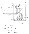
- FIG. 1 shows a schematic sectional view through a security laser scanner 10 according to the invention, which will also be referred to simply as a scanner below.
- a light emitting unit 12 for emitting pulsed transmitted light beams 16 has at least four individual VCSEL laser diodes 18-1 to 18-4.
- the transmitted light beams 16 are directed via a deflection unit 20 into a monitoring area 22 and there remitted from an optionally present object.
- the light deflection unit 20 is designed as a rotating mirror, which rotates continuously by driving a motor 24 about a rotation axis 26. The respective angular position is detected by an encoder 28.
- the transmitted light beams 16 thus cover the monitoring area 22 generated by the rotational movement.
- the remitted light returns to the scanner 10, is guided by the deflection unit 20 and by a receiving optical system 32 onto a light receiver 34, for example a photodiode, and detected there.
- the received light range defined by the receiving optics 32 is represented by its marginal rays 30.
- the light receiver 34 generates, from the transmitted light pulses remitted by the object in the monitoring area 22, corresponding received signals, which are conducted via a line 36 to an evaluation unit 38. Based on the received signal of the light receiver 34, it is possible to deduce the angular position of the deflection unit 20 from the angular position of detected objects in the monitoring area 22 by means of the encoder 28.
- the transit time of the individual laser light pulses from their emission to the reception after reflection on the object in the monitoring area 22 is determined. From the light transit time, the distance of the object from the sensor 10 is closed using the speed of light. For this, the evaluation unit 38 is connected to the laser diodes 18-1 to 18-4, the light receiver 34, the motor 24 and the encoder 28. Thus, two-dimensional polar coordinates of all objects in the monitoring area 22 are available via angle and distance.
- a safety switching signal can be provided via a fail-safe output 40 (also called OSSD, Output Signal Switching Device).
- the safety signal triggers, for example, an emergency stop of a connected and monitored by the sensor 10 machine.
- the evaluation unit 38 compares the object positions with the protective field, the geometry of which is predetermined or configured in the evaluation unit 38 by corresponding parameters. Thus, the evaluation unit 38 detects whether a protective field is violated, that is, whether an inadmissible object is located therein, and switches the fail-safe output 40 depending on the result.
- All mentioned functional components are arranged in a housing 38 which has a front screen 44 in the region of the light exit and light entry.
- the windshield 44 is substantially cylindrical to allow a large, if possible, 360 ° field of view.
- FIG. 2 Illustrates in a front view of the receiving optical system 24, that is seen along the optical axis 26, the positions of the laser diodes 18-1 to 18-4, which are arranged uniformly distributed on the circumference of the receiver aperture. In principle, you can Also, more than four, for example, eight or ten laser diodes to increase the radiant power to be arranged on the circumference.
- Fig. 3a to 3d are views of the deflection unit 20 in the direction of the received light beams to illustrate the course and the positioning of the transmitted light beams 16-1 to 16-4, in particular in relation to the received light region 30 of the remitted light.
- the in itself elliptical rotating mirror 20 is shown in such a view, ie in the 45 ° projection, as a circle.
- Fig. 3a corresponds to the angular position of the deflection unit 20 Fig.1 , which should be defined as 0 °.
- Shown are the points of impact of the four transmitted light beams 16-1 to 16-4 on the rotating mirror 20. With rotation of the rotating mirror 20 "hit" the impact points "in the round”. So corresponds the Fig. 3b an angular position of about 20 °, the Fig. 3c of 45 ° and the Fig. 3d finally from 90 °.
- a contamination monitoring unit 50 is provided with which a monitoring of the windscreen 44 is possible for contamination.
- the laser diodes 18-1 to 18-4 are driven by the laser diode control unit 46 in direct succession and the remission signals from these two successive pulses of different laser diodes are compared. Since the individual laser diodes penetrate the windscreen at different locations but nevertheless touch the same object spot, an inhomogeneous contamination of the windscreen can be determined from the comparison of the remission light of the two pulses.
- the individual laser diodes can also differ in terms of their emission wavelength: z. B. can emit a laser diode in the visible spectral range and the rest at about 900nm.
Landscapes
- Engineering & Computer Science (AREA)
- Physics & Mathematics (AREA)
- Computer Networks & Wireless Communication (AREA)
- General Physics & Mathematics (AREA)
- Radar, Positioning & Navigation (AREA)
- Remote Sensing (AREA)
- Electromagnetism (AREA)
- Optical Radar Systems And Details Thereof (AREA)
Claims (8)
- Scanner laser de sécurité pour sécuriser une zone dangereuse,- avec une unité d'émission de lumière (12) pour émettre de la lumière pulsée (16-1 à 16-4) dans une zone surveillée (22),- une unité de déviation (20) qui peut tourner autour d'un axe de rotation (26) pour la déviation périodique des faisceaux de lumière émis (16-1 à 16-4) dans la zone surveillée (22),- un récepteur de lumière (34) pour générer un signal de réception à partir des impulsions de la lumière reflétées de manière diffuse par un objet dans la zone surveillée (22),- un système optique de réception (32) qui est disposé devant le récepteur de lumière (34),- une sortie des signaux de sécurité (40) avec laquelle un signal de commutation de sécurité peut être émis si une intrusion non-autorisée dans un champ de protection prédéterminé à l'intérieur de la zone surveillée (22) a été détectée par une unité d'évaluation (38),caractérisé en ce que- une unité de codeur angulaire (28) délivre un signal qui est représentatif pour la position momentanée angulaire de l'unité de déviation,- l'unité d'évaluation (38) détermine une valeur de position de la réflexion dans la zone surveillée à partir du signal d'angle et le temps entre l'émission et la réception d'une impulsion lumineuse,- l'unité d'émission de lumière (12) comprend au moins quatre diodes laser VCSEL individuelles (18-1, 18-3) dont les faisceaux lumineux s'étendent sensiblement parallèles.
- Scanner selon la revendication 1, caractérisé en ce que les diodes laser VCSEL sont agencées de telle sorte que les rayons lumineux d'émission sont disposés uniformément répartis sur la périphérie de l'ouverture du récepteur.
- Scanner selon l'une des revendications précédentes, caractérisé en ce que le système optique de réception est monté de sorte qu'il est déplaçable conjointement avec l'unité de déviation.
- Scanner selon l'une des revendications précédentes, caractérisé en ce qu'une unité de commande des diodes laser est prévue pour émettre des impulsions simultanées des diodes laser individuelles.
- Scanner selon l'une des revendications précédentes, caractérisé en ce que les diodes laser individuelles sont contrôlables séparément par l'unité de commande des diodes laser, par laquelle l'impulsion totale qui résulte de la superposition des impulsions individuelles est réglable concernant la hauteur d'impulsion, la largeur et la forme.
- Scanner selon la revendication 5, caractérisé en ce qu'une unité de détection de la contamination de la vitre avant est prévue avec laquelle les signaux de réception des réflexions des diodes laser individuelles et différentes peuvent être évalués et par cela une contamination de la vitre avant peut être déterminée.
- Scanner selon l'une des revendications précédentes, caractérisé en ce que les diodes laser émettent de la lumière des longueurs d'onde différentes.
- Scanner selon l'une des revendications précédentes, caractérisé en ce que les rayons lumineux d'émission sont inclinés avec un petit angle vers l'axe optique de l'optique de réception.
Priority Applications (1)
| Application Number | Priority Date | Filing Date | Title |
|---|---|---|---|
| EP10160720A EP2381268B1 (fr) | 2010-04-22 | 2010-04-22 | Scanner laser de sécurité |
Applications Claiming Priority (1)
| Application Number | Priority Date | Filing Date | Title |
|---|---|---|---|
| EP10160720A EP2381268B1 (fr) | 2010-04-22 | 2010-04-22 | Scanner laser de sécurité |
Publications (2)
| Publication Number | Publication Date |
|---|---|
| EP2381268A1 EP2381268A1 (fr) | 2011-10-26 |
| EP2381268B1 true EP2381268B1 (fr) | 2012-06-27 |
Family
ID=42937233
Family Applications (1)
| Application Number | Title | Priority Date | Filing Date |
|---|---|---|---|
| EP10160720A Active EP2381268B1 (fr) | 2010-04-22 | 2010-04-22 | Scanner laser de sécurité |
Country Status (1)
| Country | Link |
|---|---|
| EP (1) | EP2381268B1 (fr) |
Cited By (2)
| Publication number | Priority date | Publication date | Assignee | Title |
|---|---|---|---|---|
| DE102017105994A1 (de) | 2017-03-21 | 2018-09-27 | Valeo Schalter Und Sensoren Gmbh | Sendeeinrichtung für eine optische Erfassungseinrichtung eines Kraftfahrzeugs mit VCSEL-Laserdioden, optische Erfassungseinrichtung, Fahrerassistenzsystem sowie Kraftfahrzeug |
| WO2023178108A1 (fr) * | 2022-03-18 | 2023-09-21 | Motional Ad Llc | Fenêtre lidar à réduction de faux signal |
Families Citing this family (8)
| Publication number | Priority date | Publication date | Assignee | Title |
|---|---|---|---|---|
| DE102011000978A1 (de) | 2011-02-28 | 2012-08-30 | Sick Ag | Optoelektronischer Sensor und Verfahren zur Erfassung von Objekten |
| EP2682780B1 (fr) * | 2012-07-04 | 2014-04-23 | Sick Ag | Procédé de détection et de détermination de position sécurisée d'objets et dispositif de sécurité |
| DE102017213726A1 (de) * | 2017-08-08 | 2019-02-14 | Robert Bosch Gmbh | Sensorvorrichtung zur Detektion eines Objekts |
| DE102018101846A1 (de) | 2018-01-26 | 2019-08-01 | Sick Ag | Optoelektronischer Sensor und Verfahren zur Erfassung von Objekten |
| CN110531369B (zh) * | 2018-05-25 | 2021-11-30 | 深圳市速腾聚创科技有限公司 | 一种固态激光雷达 |
| CN111273254B (zh) * | 2018-12-04 | 2024-05-10 | 无锡驭风智研科技有限公司 | 一种激光雷达发射装置及激光雷达 |
| CN111273255B (zh) * | 2018-12-04 | 2024-06-21 | 无锡驭风智研科技有限公司 | 一种激光雷达发射装置及激光雷达 |
| CN111766586B (zh) * | 2019-03-29 | 2024-07-05 | 宁波舜宇车载光学技术有限公司 | 激光雷达探测系统和激光雷达探测方法 |
Family Cites Families (5)
| Publication number | Priority date | Publication date | Assignee | Title |
|---|---|---|---|---|
| US5455669A (en) * | 1992-12-08 | 1995-10-03 | Erwin Sick Gmbh Optik-Elektronik | Laser range finding apparatus |
| DE4340756C5 (de) | 1992-12-08 | 2006-08-10 | Sick Ag | Laserabstandsermittlungsvorrichtung |
| DE19735037C2 (de) * | 1997-08-13 | 1999-06-02 | Schmersal Eot Gmbh & Co Kg | Vorrichtung zum Orten von in einen zu überwachenden Raumbereich eindringenden Objekten |
| DE19735038C2 (de) * | 1997-08-13 | 1999-07-15 | Schmersal Eot Gmbh & Co Kg | Vorrichtung zum Orten von in einen zu überwachenden Raumbereich eindringenden Objekten |
| DE10244641A1 (de) | 2002-09-25 | 2004-04-08 | Ibeo Automobile Sensor Gmbh | Optoelektronische Erfassungseinrichtung |
-
2010
- 2010-04-22 EP EP10160720A patent/EP2381268B1/fr active Active
Cited By (3)
| Publication number | Priority date | Publication date | Assignee | Title |
|---|---|---|---|---|
| DE102017105994A1 (de) | 2017-03-21 | 2018-09-27 | Valeo Schalter Und Sensoren Gmbh | Sendeeinrichtung für eine optische Erfassungseinrichtung eines Kraftfahrzeugs mit VCSEL-Laserdioden, optische Erfassungseinrichtung, Fahrerassistenzsystem sowie Kraftfahrzeug |
| WO2018172247A1 (fr) | 2017-03-21 | 2018-09-27 | Valeo Schalter Und Sensoren Gmbh | Dispositif d'émission pour un dispositif de détection optique d'un véhicule à moteur comportant des diodes laser vcsel, dispositif de détection optique, système d'aide à la conduite et véhicule à moteur |
| WO2023178108A1 (fr) * | 2022-03-18 | 2023-09-21 | Motional Ad Llc | Fenêtre lidar à réduction de faux signal |
Also Published As
| Publication number | Publication date |
|---|---|
| EP2381268A1 (fr) | 2011-10-26 |
Similar Documents
| Publication | Publication Date | Title |
|---|---|---|
| EP2381268B1 (fr) | Scanner laser de sécurité | |
| EP2482094B1 (fr) | Capteur optoélectronique mesurant l'éloignement et procédé de détection d'objet | |
| EP2927711B1 (fr) | Lecteur laser et procédé de saisie sécurisée d'objets | |
| DE4340756C5 (de) | Laserabstandsermittlungsvorrichtung | |
| EP3136127B1 (fr) | Capteur telemetrique et procede comprenant un capteur telemetrique | |
| DE102012102395B3 (de) | Optoelektronischer Sensor und Verfahren zum Testen der Lichtdurchlässigkeit einer Frontscheibe | |
| DE4345448C2 (de) | Laserabstandsermittlungsvorrichtung | |
| EP2124069B1 (fr) | Système LIDAR omnidirectionnel | |
| EP3078985B1 (fr) | Capteur optoelectronique et procede de surveillance de transmission d'un disque frontal | |
| EP3699638B1 (fr) | Capteur optoélectronique et procédé de détection d'un objet | |
| EP2447733B1 (fr) | Capteur optoélectronique | |
| EP2645125B1 (fr) | Laser scanner et procédé destiné à la détection d'objets dans une zone de surveillance | |
| EP2378309B2 (fr) | Capteur optoélectronique et procédé de production d'informations sur des objets dans une zone de surveillance | |
| DE102016114995A1 (de) | Vorrichtung und Verfahren zur Aufnahme von Entfernungsbildern | |
| EP1543344A2 (fr) | Dispositif de detection optoelectronique | |
| EP2296002A1 (fr) | Scanner optoélectronique pour la détermination de distances en azimut et élévation | |
| EP3388857B1 (fr) | Dispositif de balayage laser et procédé de vérification de la capacité de fonctionnement | |
| DE102011000978A1 (de) | Optoelektronischer Sensor und Verfahren zur Erfassung von Objekten | |
| EP2375266B1 (fr) | Capteur optoélectronique et procédé de sécurisation | |
| EP4086661A1 (fr) | Capteur optoélectronique et procédé de surveillance d'une vitre avant | |
| EP3699637B1 (fr) | Capteur optoélectronique et procédé de détection d'un objet | |
| DE202012101007U1 (de) | Optoelektronischer Sensor | |
| DE102013018799A1 (de) | Verfahren und Vorrichtung zum optischen Bestimmen von Abständen zu Objekten, insbesondere zu Hindernissen für Fahrzeuge, in einem Überwachungsbereich | |
| EP2508914A1 (fr) | Dispositif de détection optique | |
| DE9321459U1 (de) | Laserabstandsermittlungsvorrichtung |
Legal Events
| Date | Code | Title | Description |
|---|---|---|---|
| AK | Designated contracting states |
Kind code of ref document: A1 Designated state(s): AT BE BG CH CY CZ DE DK EE ES FI FR GB GR HR HU IE IS IT LI LT LU LV MC MK MT NL NO PL PT RO SE SI SK SM TR |
|
| AX | Request for extension of the european patent |
Extension state: AL BA ME RS |
|
| PUAI | Public reference made under article 153(3) epc to a published international application that has entered the european phase |
Free format text: ORIGINAL CODE: 0009012 |
|
| 17P | Request for examination filed |
Effective date: 20111031 |
|
| RIC1 | Information provided on ipc code assigned before grant |
Ipc: G01S 17/02 20060101ALI20111207BHEP Ipc: G01S 7/483 20060101ALI20111207BHEP Ipc: G01S 7/481 20060101AFI20111207BHEP |
|
| GRAP | Despatch of communication of intention to grant a patent |
Free format text: ORIGINAL CODE: EPIDOSNIGR1 |
|
| GRAS | Grant fee paid |
Free format text: ORIGINAL CODE: EPIDOSNIGR3 |
|
| GRAA | (expected) grant |
Free format text: ORIGINAL CODE: 0009210 |
|
| AK | Designated contracting states |
Kind code of ref document: B1 Designated state(s): AT BE BG CH CY CZ DE DK EE ES FI FR GB GR HR HU IE IS IT LI LT LU LV MC MK MT NL NO PL PT RO SE SI SK SM TR |
|
| REG | Reference to a national code |
Ref country code: GB Ref legal event code: FG4D Free format text: NOT ENGLISH |
|
| REG | Reference to a national code |
Ref country code: CH Ref legal event code: EP |
|
| REG | Reference to a national code |
Ref country code: AT Ref legal event code: REF Ref document number: 564504 Country of ref document: AT Kind code of ref document: T Effective date: 20120715 |
|
| REG | Reference to a national code |
Ref country code: IE Ref legal event code: FG4D Free format text: LANGUAGE OF EP DOCUMENT: GERMAN |
|
| REG | Reference to a national code |
Ref country code: DE Ref legal event code: R096 Ref document number: 502010000947 Country of ref document: DE Effective date: 20120823 |
|
| PG25 | Lapsed in a contracting state [announced via postgrant information from national office to epo] |
Ref country code: SE Free format text: LAPSE BECAUSE OF FAILURE TO SUBMIT A TRANSLATION OF THE DESCRIPTION OR TO PAY THE FEE WITHIN THE PRESCRIBED TIME-LIMIT Effective date: 20120627 Ref country code: NO Free format text: LAPSE BECAUSE OF FAILURE TO SUBMIT A TRANSLATION OF THE DESCRIPTION OR TO PAY THE FEE WITHIN THE PRESCRIBED TIME-LIMIT Effective date: 20120927 Ref country code: FI Free format text: LAPSE BECAUSE OF FAILURE TO SUBMIT A TRANSLATION OF THE DESCRIPTION OR TO PAY THE FEE WITHIN THE PRESCRIBED TIME-LIMIT Effective date: 20120627 Ref country code: LT Free format text: LAPSE BECAUSE OF FAILURE TO SUBMIT A TRANSLATION OF THE DESCRIPTION OR TO PAY THE FEE WITHIN THE PRESCRIBED TIME-LIMIT Effective date: 20120627 |
|
| REG | Reference to a national code |
Ref country code: NL Ref legal event code: VDEP Effective date: 20120627 |
|
| REG | Reference to a national code |
Ref country code: LT Ref legal event code: MG4D Effective date: 20120627 |
|
| PG25 | Lapsed in a contracting state [announced via postgrant information from national office to epo] |
Ref country code: SI Free format text: LAPSE BECAUSE OF FAILURE TO SUBMIT A TRANSLATION OF THE DESCRIPTION OR TO PAY THE FEE WITHIN THE PRESCRIBED TIME-LIMIT Effective date: 20120627 Ref country code: GR Free format text: LAPSE BECAUSE OF FAILURE TO SUBMIT A TRANSLATION OF THE DESCRIPTION OR TO PAY THE FEE WITHIN THE PRESCRIBED TIME-LIMIT Effective date: 20120928 Ref country code: LV Free format text: LAPSE BECAUSE OF FAILURE TO SUBMIT A TRANSLATION OF THE DESCRIPTION OR TO PAY THE FEE WITHIN THE PRESCRIBED TIME-LIMIT Effective date: 20120627 Ref country code: HR Free format text: LAPSE BECAUSE OF FAILURE TO SUBMIT A TRANSLATION OF THE DESCRIPTION OR TO PAY THE FEE WITHIN THE PRESCRIBED TIME-LIMIT Effective date: 20120627 |
|
| PG25 | Lapsed in a contracting state [announced via postgrant information from national office to epo] |
Ref country code: IS Free format text: LAPSE BECAUSE OF FAILURE TO SUBMIT A TRANSLATION OF THE DESCRIPTION OR TO PAY THE FEE WITHIN THE PRESCRIBED TIME-LIMIT Effective date: 20121027 Ref country code: CY Free format text: LAPSE BECAUSE OF FAILURE TO SUBMIT A TRANSLATION OF THE DESCRIPTION OR TO PAY THE FEE WITHIN THE PRESCRIBED TIME-LIMIT Effective date: 20120627 Ref country code: SK Free format text: LAPSE BECAUSE OF FAILURE TO SUBMIT A TRANSLATION OF THE DESCRIPTION OR TO PAY THE FEE WITHIN THE PRESCRIBED TIME-LIMIT Effective date: 20120627 Ref country code: RO Free format text: LAPSE BECAUSE OF FAILURE TO SUBMIT A TRANSLATION OF THE DESCRIPTION OR TO PAY THE FEE WITHIN THE PRESCRIBED TIME-LIMIT Effective date: 20120627 Ref country code: EE Free format text: LAPSE BECAUSE OF FAILURE TO SUBMIT A TRANSLATION OF THE DESCRIPTION OR TO PAY THE FEE WITHIN THE PRESCRIBED TIME-LIMIT Effective date: 20120627 Ref country code: CZ Free format text: LAPSE BECAUSE OF FAILURE TO SUBMIT A TRANSLATION OF THE DESCRIPTION OR TO PAY THE FEE WITHIN THE PRESCRIBED TIME-LIMIT Effective date: 20120627 |
|
| PG25 | Lapsed in a contracting state [announced via postgrant information from national office to epo] |
Ref country code: PL Free format text: LAPSE BECAUSE OF FAILURE TO SUBMIT A TRANSLATION OF THE DESCRIPTION OR TO PAY THE FEE WITHIN THE PRESCRIBED TIME-LIMIT Effective date: 20120627 Ref country code: IT Free format text: LAPSE BECAUSE OF FAILURE TO SUBMIT A TRANSLATION OF THE DESCRIPTION OR TO PAY THE FEE WITHIN THE PRESCRIBED TIME-LIMIT Effective date: 20120627 Ref country code: PT Free format text: LAPSE BECAUSE OF FAILURE TO SUBMIT A TRANSLATION OF THE DESCRIPTION OR TO PAY THE FEE WITHIN THE PRESCRIBED TIME-LIMIT Effective date: 20121029 |
|
| PG25 | Lapsed in a contracting state [announced via postgrant information from national office to epo] |
Ref country code: NL Free format text: LAPSE BECAUSE OF FAILURE TO SUBMIT A TRANSLATION OF THE DESCRIPTION OR TO PAY THE FEE WITHIN THE PRESCRIBED TIME-LIMIT Effective date: 20120627 |
|
| PG25 | Lapsed in a contracting state [announced via postgrant information from national office to epo] |
Ref country code: DK Free format text: LAPSE BECAUSE OF FAILURE TO SUBMIT A TRANSLATION OF THE DESCRIPTION OR TO PAY THE FEE WITHIN THE PRESCRIBED TIME-LIMIT Effective date: 20120627 |
|
| PLBE | No opposition filed within time limit |
Free format text: ORIGINAL CODE: 0009261 |
|
| STAA | Information on the status of an ep patent application or granted ep patent |
Free format text: STATUS: NO OPPOSITION FILED WITHIN TIME LIMIT |
|
| 26N | No opposition filed |
Effective date: 20130328 |
|
| REG | Reference to a national code |
Ref country code: DE Ref legal event code: R097 Ref document number: 502010000947 Country of ref document: DE Effective date: 20130328 |
|
| PG25 | Lapsed in a contracting state [announced via postgrant information from national office to epo] |
Ref country code: BG Free format text: LAPSE BECAUSE OF FAILURE TO SUBMIT A TRANSLATION OF THE DESCRIPTION OR TO PAY THE FEE WITHIN THE PRESCRIBED TIME-LIMIT Effective date: 20120927 |
|
| BERE | Be: lapsed |
Owner name: SICK A.G. Effective date: 20130430 |
|
| PG25 | Lapsed in a contracting state [announced via postgrant information from national office to epo] |
Ref country code: ES Free format text: LAPSE BECAUSE OF FAILURE TO SUBMIT A TRANSLATION OF THE DESCRIPTION OR TO PAY THE FEE WITHIN THE PRESCRIBED TIME-LIMIT Effective date: 20121008 |
|
| PG25 | Lapsed in a contracting state [announced via postgrant information from national office to epo] |
Ref country code: MC Free format text: LAPSE BECAUSE OF FAILURE TO SUBMIT A TRANSLATION OF THE DESCRIPTION OR TO PAY THE FEE WITHIN THE PRESCRIBED TIME-LIMIT Effective date: 20120627 |
|
| REG | Reference to a national code |
Ref country code: IE Ref legal event code: MM4A |
|
| PG25 | Lapsed in a contracting state [announced via postgrant information from national office to epo] |
Ref country code: BE Free format text: LAPSE BECAUSE OF NON-PAYMENT OF DUE FEES Effective date: 20130430 |
|
| PG25 | Lapsed in a contracting state [announced via postgrant information from national office to epo] |
Ref country code: IE Free format text: LAPSE BECAUSE OF NON-PAYMENT OF DUE FEES Effective date: 20130422 |
|
| PG25 | Lapsed in a contracting state [announced via postgrant information from national office to epo] |
Ref country code: MT Free format text: LAPSE BECAUSE OF FAILURE TO SUBMIT A TRANSLATION OF THE DESCRIPTION OR TO PAY THE FEE WITHIN THE PRESCRIBED TIME-LIMIT Effective date: 20120627 |
|
| PG25 | Lapsed in a contracting state [announced via postgrant information from national office to epo] |
Ref country code: SM Free format text: LAPSE BECAUSE OF FAILURE TO SUBMIT A TRANSLATION OF THE DESCRIPTION OR TO PAY THE FEE WITHIN THE PRESCRIBED TIME-LIMIT Effective date: 20120627 |
|
| PG25 | Lapsed in a contracting state [announced via postgrant information from national office to epo] |
Ref country code: TR Free format text: LAPSE BECAUSE OF FAILURE TO SUBMIT A TRANSLATION OF THE DESCRIPTION OR TO PAY THE FEE WITHIN THE PRESCRIBED TIME-LIMIT Effective date: 20120627 |
|
| PG25 | Lapsed in a contracting state [announced via postgrant information from national office to epo] |
Ref country code: MK Free format text: LAPSE BECAUSE OF FAILURE TO SUBMIT A TRANSLATION OF THE DESCRIPTION OR TO PAY THE FEE WITHIN THE PRESCRIBED TIME-LIMIT Effective date: 20120627 Ref country code: LU Free format text: LAPSE BECAUSE OF NON-PAYMENT OF DUE FEES Effective date: 20130422 Ref country code: HU Free format text: LAPSE BECAUSE OF FAILURE TO SUBMIT A TRANSLATION OF THE DESCRIPTION OR TO PAY THE FEE WITHIN THE PRESCRIBED TIME-LIMIT; INVALID AB INITIO Effective date: 20100422 |
|
| REG | Reference to a national code |
Ref country code: FR Ref legal event code: PLFP Year of fee payment: 7 |
|
| REG | Reference to a national code |
Ref country code: AT Ref legal event code: MM01 Ref document number: 564504 Country of ref document: AT Kind code of ref document: T Effective date: 20150422 |
|
| PG25 | Lapsed in a contracting state [announced via postgrant information from national office to epo] |
Ref country code: AT Free format text: LAPSE BECAUSE OF NON-PAYMENT OF DUE FEES Effective date: 20150422 |
|
| REG | Reference to a national code |
Ref country code: FR Ref legal event code: PLFP Year of fee payment: 8 |
|
| REG | Reference to a national code |
Ref country code: FR Ref legal event code: PLFP Year of fee payment: 9 |
|
| PGFP | Annual fee paid to national office [announced via postgrant information from national office to epo] |
Ref country code: CH Payment date: 20190424 Year of fee payment: 10 |
|
| REG | Reference to a national code |
Ref country code: CH Ref legal event code: PL |
|
| PG25 | Lapsed in a contracting state [announced via postgrant information from national office to epo] |
Ref country code: LI Free format text: LAPSE BECAUSE OF NON-PAYMENT OF DUE FEES Effective date: 20200430 Ref country code: CH Free format text: LAPSE BECAUSE OF NON-PAYMENT OF DUE FEES Effective date: 20200430 |
|
| PGFP | Annual fee paid to national office [announced via postgrant information from national office to epo] |
Ref country code: GB Payment date: 20220425 Year of fee payment: 13 Ref country code: FR Payment date: 20220420 Year of fee payment: 13 |
|
| GBPC | Gb: european patent ceased through non-payment of renewal fee |
Effective date: 20230422 |
|
| PG25 | Lapsed in a contracting state [announced via postgrant information from national office to epo] |
Ref country code: GB Free format text: LAPSE BECAUSE OF NON-PAYMENT OF DUE FEES Effective date: 20230422 |
|
| PG25 | Lapsed in a contracting state [announced via postgrant information from national office to epo] |
Ref country code: GB Free format text: LAPSE BECAUSE OF NON-PAYMENT OF DUE FEES Effective date: 20230422 Ref country code: FR Free format text: LAPSE BECAUSE OF NON-PAYMENT OF DUE FEES Effective date: 20230430 |
|
| PGFP | Annual fee paid to national office [announced via postgrant information from national office to epo] |
Ref country code: DE Payment date: 20250417 Year of fee payment: 16 |