EP2383144A2 - Dispositif de liaison d'un siège de véhicule sur une unité rotative, unité rotative et siège de véhicule - Google Patents
Dispositif de liaison d'un siège de véhicule sur une unité rotative, unité rotative et siège de véhicule Download PDFInfo
- Publication number
- EP2383144A2 EP2383144A2 EP11003363A EP11003363A EP2383144A2 EP 2383144 A2 EP2383144 A2 EP 2383144A2 EP 11003363 A EP11003363 A EP 11003363A EP 11003363 A EP11003363 A EP 11003363A EP 2383144 A2 EP2383144 A2 EP 2383144A2
- Authority
- EP
- European Patent Office
- Prior art keywords
- hollow profile
- vehicle seat
- profile means
- adaptation elements
- elements
- Prior art date
- Legal status (The legal status is an assumption and is not a legal conclusion. Google has not performed a legal analysis and makes no representation as to the accuracy of the status listed.)
- Withdrawn
Links
- 230000006978 adaptation Effects 0.000 claims abstract description 52
- 230000002787 reinforcement Effects 0.000 claims abstract description 3
- 230000007246 mechanism Effects 0.000 description 9
- 238000005452 bending Methods 0.000 description 6
- 238000010276 construction Methods 0.000 description 5
- 230000000694 effects Effects 0.000 description 3
- 229910000831 Steel Inorganic materials 0.000 description 2
- 238000005553 drilling Methods 0.000 description 2
- 239000000463 material Substances 0.000 description 2
- 230000000087 stabilizing effect Effects 0.000 description 2
- 239000010959 steel Substances 0.000 description 2
- 238000010521 absorption reaction Methods 0.000 description 1
- 239000000853 adhesive Substances 0.000 description 1
- 230000001070 adhesive effect Effects 0.000 description 1
- 230000001419 dependent effect Effects 0.000 description 1
- 238000006073 displacement reaction Methods 0.000 description 1
- 238000009434 installation Methods 0.000 description 1
- 230000007257 malfunction Effects 0.000 description 1
- 238000004519 manufacturing process Methods 0.000 description 1
- 230000004048 modification Effects 0.000 description 1
- 238000012986 modification Methods 0.000 description 1
- 238000003825 pressing Methods 0.000 description 1
- 238000005476 soldering Methods 0.000 description 1
- 230000003068 static effect Effects 0.000 description 1
- 238000003860 storage Methods 0.000 description 1
- 238000003466 welding Methods 0.000 description 1
Images

Classifications
-
- B—PERFORMING OPERATIONS; TRANSPORTING
- B60—VEHICLES IN GENERAL
- B60N—SEATS SPECIALLY ADAPTED FOR VEHICLES; VEHICLE PASSENGER ACCOMMODATION NOT OTHERWISE PROVIDED FOR
- B60N2/00—Seats specially adapted for vehicles; Arrangement or mounting of seats in vehicles
- B60N2/02—Seats specially adapted for vehicles; Arrangement or mounting of seats in vehicles the seat or part thereof being movable, e.g. adjustable
- B60N2/04—Seats specially adapted for vehicles; Arrangement or mounting of seats in vehicles the seat or part thereof being movable, e.g. adjustable the whole seat being movable
- B60N2/14—Seats specially adapted for vehicles; Arrangement or mounting of seats in vehicles the seat or part thereof being movable, e.g. adjustable the whole seat being movable rotatable, e.g. to permit easy access
-
- B—PERFORMING OPERATIONS; TRANSPORTING
- B60—VEHICLES IN GENERAL
- B60N—SEATS SPECIALLY ADAPTED FOR VEHICLES; VEHICLE PASSENGER ACCOMMODATION NOT OTHERWISE PROVIDED FOR
- B60N2/00—Seats specially adapted for vehicles; Arrangement or mounting of seats in vehicles
- B60N2/02—Seats specially adapted for vehicles; Arrangement or mounting of seats in vehicles the seat or part thereof being movable, e.g. adjustable
- B60N2/04—Seats specially adapted for vehicles; Arrangement or mounting of seats in vehicles the seat or part thereof being movable, e.g. adjustable the whole seat being movable
- B60N2/06—Seats specially adapted for vehicles; Arrangement or mounting of seats in vehicles the seat or part thereof being movable, e.g. adjustable the whole seat being movable slidable
Definitions
- Rotary seats in vehicles and associated rotating units have already become known in a variety of configurations.
- a turntable it is in particular possible to accommodate a vehicle seat about an upright or vertical axis rotatably in a vehicle.
- the storage of the seat in the vehicle must be stable and space-saving.
- the invention has for its object to improve arrangements for accommodated via a rotating mechanism vehicle seats technically and economically, in particular with regard to a space-saving design with high mechanical stability.
- the invention relates to a device for connecting a vehicle seat to a rotary unit, which is designed for a rotational movement of the vehicle seat about an upright axis of rotation and which is connected to an upper side with the vehicle seat and on a lower side stationary.
- the attachment device acts in particular connecting between the vehicle seat and the turntable.
- the attachment device may for example be provided separately and / or be present on the turntable or the vehicle seat.
- the essence of the invention is that for attaching the upper side of the rotary unit, with respect to the rotation axis opposite plate-shaped adaptation elements are provided with a free distance from each other, wherein the adaptation elements are connected to the common reinforcement via hollow profile means which are placed on the adaptation elements and the hollow profile means at least comprise hollow profile sections spaced from each other each span the free distance between the adaptation elements and extend after a change in direction along the adaptation elements.
- the at least partially hollow hollow profile means serve to stiffen the connecting device formed with the two adaptation elements.
- the attachment device is on the one hand connected to the vehicle seat and on the other hand with a rotatable part of the rotary unit, which has a rotating mechanism, the z. B. comprises a pressing part, in particular made of steel in conjunction with a ball bearing.
- the plate-shaped elements are configured for a respective suitable adaptation.
- the adaptation elements can be individually matched with regard to shape, size and material to the respective vehicle seat or intended use and can have, for example, corresponding hole patterns for screwing the adaptation elements to suitably prepared counterpart sections.
- an increased mechanical stability can be set up advantageously with the arrangement according to the invention, in particular a sufficiently high bending or torsional stability can be set up in a space-saving and lightweight manner, which is possible via the hollow profile means in combination with the plate-like adaptation elements.
- the hollow profile means can be fixed on the upper side of the adaptation elements, that is to say on the upper side directed toward the vehicle seat, and / or on the lower side, that is to say on the underside facing away from the vehicle seat.
- the hollow profile means are fixed on the respective side of the adaptation elements not only placed in one place, but extend over substantial portions of the adaptation elements.
- the direction change can be realized with a radius or at an angle, wherein the change of direction takes place in particular according to an angle of approximately 90 degrees.
- the hollow profile means extend in particular parallel to a support side or in the direction of a longitudinal extent of the adaptation elements, for example in the direction of their longitudinal edges or outer edges.
- the hollow profile means can run directly adjacent to the edges or slightly offset thereto. If necessary, the stiffening effect can be further increased by the hollow profile means also extending in sections in the direction of a width dimension of the adaptation elements or transversely to their longitudinal extent.
- the hollow profile means are preferably formed linear, with branched forms are conceivable with z. B. sections in T and / or V shape.
- the hollow profile means are designed in particular as closed in cross-section hollow profiles, for. B. as a cylindrical pipe or box-shaped polygonal profile.
- the hollow profile means may alternatively also have an open shape, for example in U- or trough form or be provided with Masterial recesses in walls of the hollow profile means.
- the hollow profile means may preferably be flat or linear in fixed contact with flat opposing sections on the adaptation elements.
- This line or surface contact can be advantageously realized in particular by welding, soldering or adhesive connection, but also for example by riveting or screwing z. B. via a plurality of screw connections between the hollow profile means and the adaptation elements.
- the hollow profile means may advantageously have an at least approximately rectangular or curved basic shape or an annular plan.
- the hollow profile means are formed essentially of an elongated profile.
- An elongated profile is easily cut to length and then brought into a desired shape.
- a variety of such long profiles in different shapes, dimensions or wall thicknesses and materials is available as standard.
- the hollow profile means comprise a tubular element.
- a pipe element is a comparatively inexpensive component and has a low weight with high stability.
- the pipe element is in particular hollow throughout.
- In walls of the tubular element can also openings z. B. holes are easily inserted, z. B. to screw or plug in through these fasteners.
- the tubular element can be continuously closed-walled or at least partially slotted or provided with openings.
- the hollow profile means have a frame-like basic shape.
- the hollow profile means may be formed as a hollow profile frame, which runs in particular along outer sides of the adaptation elements.
- the hollow profile frame can also be continuous or partially open as z. B. be formed U-shaped profile.
- z. B. be formed U-shaped profile.
- the hollow profile frame comprises in particular opposite and miteinender connected hollow profile sections, which can be particularly well stiffen the connected to the hollow profile frame adaptation elements.
- space can be left for adjacent elements of the turntable or the vehicle seat by the free space present within the hollow profile frame.
- the hollow profile means are integrally formed.
- the hollow profile means comprise an integrally formed tubular profile with merged ends, which may be connected or spaced zueinender.
- the hollow profile means may be formed, in particular, from a construction element available as standard, such as a round, tubular or square profile.
- the hollow profile means may be formed, for example, by an oblong hollow profile bent at four bending points by 90 degrees.
- the two ends of the hollow profile frame thus formed can be separated from each other at a distance from each other or connected to each other.
- This can be firmly connected via a welded joint or the like. This results in a stiffening of the adaptation elements acting over the entire extent of the adaptation elements.
- With the one-piece nature of the hollow profile means also their production and their installation on the adaptation elements is particularly easy. But it is also a multi-part construction of the hollow profile means not excluded, z. B. frame with two or more in particular interconnected frame sections or with a double frame, which comprises two frames, for example, a larger frame surrounds a smaller frame outside or surrounds.
- the hollow profile means are formed along a spatial line, wherein the space line extends over the two adaptation elements and the free distance between the adaptation elements.
- the particular uninterrupted and paragraph-free continuous space line can be particularly important sections of the Extension elements extend.
- the stiffening effect of the hollow profile means can be effective in all areas of the adaptation elements.
- the hollow profile means may comprise a substantially closed tubular element, in particular in round, oval or polygonal shape.
- the stabilizing properties of the hollow profile means can be influenced via the outer shape of the tubular element.
- a polygonal profile can form a larger contact surface with the adaptation elements or, if appropriate, be better suited for the attachment of further elements.
- the hollow profile means are formed over at least substantial portions in the longitudinal direction of the adaptation elements.
- a bending or torsional rigidity of the adaptation elements can be increased, in particular in one direction, which, due to the design, without stiffening hollow profiled means, is particularly prone to bending or twisting.
- the hollow profile means are at least substantially hollow, for example tubular or tubular.
- the hollow profile means themselves have a high bending or torsional stability with low weight or are very stiff and mechanically stable against deformation.
- hollow portions of the hollow profile means non-hollow portions are present.
- the hollow profile means are formed on the outside around an area in which pivot bearing means of the rotary unit can be accommodated. So remains in the area inside between the hollow profile means space for sections of the turntable.
- a height dimension of the attachment device in the direction of the vertical axis can advantageously be very low according to the invention stay.
- the adaptation elements are plate-shaped, so that only their thickness contributes to the height dimension
- the patch hollow profile sections are very shallow and carry only with z.
- the invention also relates to a rotary unit for a rotational movement of a vehicle seat about an upright axis of rotation, wherein the rotary unit on an upper side with the vehicle seat and on a lower side is stationary attachable.
- the rotary unit comprises an attachment device according to one of the aforementioned embodiments.
- FIG. 1 shows a rotary unit 1 according to the invention for a not shown to a vertical axis S according to z. B. arrow P1 rotatable vehicle seat.
- the rotary unit 1 comprises an attachment device according to the invention, which is explained below.
- the turntable 1 is held stationary via a bottom or, for example, with a vehicle floor (not shown) firmly screwed.
- the underside of the rotary unit 1 comprises a base 2 with a front base plate 2a and a rear base plate 2b, for example, via screws 4, 5 at the front or via screws 6, 7 in a rear area relative to a vehicle seat attachable thereto in the normal position fixed to the Vehicle floor are screwed.
- the two base plates 2b, 2b are rigidly connected to a frame-like or horizontally oriented round tube 3 welded thereto.
- a rotary bearing unit 8 is added.
- the rotary bearing unit 8 is constructed according to known rotary bearing units with bearing bodies and bearing rings and is therefore not explained in detail.
- the rotary bearing unit 8 comprises in particular the actual rotary mechanism with pressed parts made of steel and an integrated ball bearing.
- the turntable 1 comprises a rail guide with slide rails which can be extended in the direction of the arrow P2 and which comprises a slide rail 9 which is right in relation to a normal seating direction and a left slide rail 10 which is telescopically received relative to respective fixed fixed rails 9a, 10a.
- the rail guide works according to known rail guides for a sliding movement of a vehicle seat and is therefore also not further explained.
- an attachment device designed as a rotary plate 14, via which the connection to the vehicle seat.
- the rotary plate 14 has adaptation elements or a first rotary plate element 14a and a second rotary plate element 14b.
- the rotary plate 14 is stiffened by hollow profile means, which are formed here as a bent round tube 15.
- a locking lever 16 is present, which is manually operated by a person to the in FIG. 1 unlocked illustrated vehicle seat, so that the vehicle seat about the axis S is rotatable, for example up to 180 degrees or more.
- the lock lever 16 is equipped with a pivot mechanism 17 for releasing the lock.
- connection of the vehicle seat with the turntable 1 via the slide rails 9 and 10 can be done via connecting screws 19.
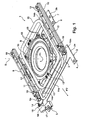
- FIG. 2 alone shows the rotary plate 14 with the circular tube 15.
- the rotary plate elements 14 a and 14 b are holes 20 for the Screw 13 and further holes 22 for screwing with the slide rails 9 and 10 available.
- the round tube 15 is here welded, for example, on the respective upwardly directed to the vehicle seat top of the rotary plate elements 14a and 14b, the space-saving aligned with each other or lie on a plane.
- the round tube 15 is insbesondre in particular integrally formed and hollow throughout and forms a rectangular in shape in the basic form.
- the two ends of the round tube 15 are opposite each other over a small gap 21 and aligned with each other.
- the round tube or end sections of the hollow profile sections 15a and 15b respectively extend in the direction of a representative width B1 of the adaptation element 14a or in the direction of a representative width B2 of the adaptation element 14b over the entire width B1 or B2 between opposite longitudinal edges of the adapter elements 14a and 14b.
- the hollow profile section 15c which is separated by the gap 21 in the exemplary embodiment, could also be continuous without Gap 21 be configured.
- a force ring from the rotary plate elements 14a, 14b and the round tube 15 is formed, which can be added to the rotary unit initiated by the vehicle seat forces and forwarded without causing any relevant or critical deformations on the vehicle seat, the rotary plate 14th and / or the turntable 1 can come.
- the rotary plate 14 is formed in particular very torsion and bending stability and gives the entire turntable 1 with respect to the turntable 1 high central stiffening, which is particularly important for loads in via the slide rails 9, 10 extended state of the vehicle seat with seated person is significant.
- To reinforce contributes in particular the combined construction with the round tube 15, which is itself very light and extremely stable or torsionally stiff.
Landscapes
- Engineering & Computer Science (AREA)
- Aviation & Aerospace Engineering (AREA)
- Transportation (AREA)
- Mechanical Engineering (AREA)
- Seats For Vehicles (AREA)
Applications Claiming Priority (1)
| Application Number | Priority Date | Filing Date | Title |
|---|---|---|---|
| DE201010018664 DE102010018664B4 (de) | 2010-04-28 | 2010-04-28 | Vorrichtung zur Anbindung eines Fahrzeugsitzes an eine Dreheinheit, Dreheinheit und Fahrzeugsitz |
Publications (2)
| Publication Number | Publication Date |
|---|---|
| EP2383144A2 true EP2383144A2 (fr) | 2011-11-02 |
| EP2383144A3 EP2383144A3 (fr) | 2014-03-12 |
Family
ID=44343208
Family Applications (1)
| Application Number | Title | Priority Date | Filing Date |
|---|---|---|---|
| EP11003363.6A Withdrawn EP2383144A3 (fr) | 2010-04-28 | 2011-04-21 | Dispositif de liaison d'un siège de véhicule sur une unité rotative, unité rotative et siège de véhicule |
Country Status (2)
| Country | Link |
|---|---|
| EP (1) | EP2383144A3 (fr) |
| DE (1) | DE102010018664B4 (fr) |
Families Citing this family (1)
| Publication number | Priority date | Publication date | Assignee | Title |
|---|---|---|---|---|
| DE102019124672B3 (de) * | 2019-09-13 | 2021-02-04 | Isringhausen Gmbh & Co. Kg | Dreheinheit für einen um seine Hochachse rotierbaren Fahrzeugsitz, Crashhaken für eine solche Dreheinheit und rotierbarer Fahrzeugsitz |
Citations (3)
| Publication number | Priority date | Publication date | Assignee | Title |
|---|---|---|---|---|
| JPS6338045A (ja) * | 1986-07-31 | 1988-02-18 | Tachi S Co Ltd | 車両等の回転シ−ト |
| EP1900566A2 (fr) * | 2006-09-18 | 2008-03-19 | Grammer Ag | Siège de véhicule tournant |
| DE102007021141A1 (de) * | 2007-03-23 | 2008-09-25 | Aguti Produktentwicklung & Design Gmbh | Dreheinheit für einen Fahrzeugsitz |
Family Cites Families (7)
| Publication number | Priority date | Publication date | Assignee | Title |
|---|---|---|---|---|
| US3740014A (en) * | 1972-01-20 | 1973-06-19 | Swenson Corp | Adjustable seat assembly for vehicle |
| JPS6337045A (ja) * | 1986-08-01 | 1988-02-17 | Shinko Electric Co Ltd | 真空吸着装置 |
| DE4009212A1 (de) * | 1990-03-22 | 1991-09-26 | Ims Morat Soehne Gmbh | Fahrzeugsitz |
| KR20010010847A (ko) * | 1999-07-23 | 2001-02-15 | 류정열 | 유격 방지 구조를 가지는 자동차의 전방 시트 |
| DE10044725A1 (de) * | 2000-09-08 | 2002-03-21 | Brose Fahrzeugteile | Kraftfahrzeugsitz mit einem Sitzuntergestell |
| EP2347929B1 (fr) * | 2008-10-20 | 2016-04-13 | NHK Spring Co., Ltd. | Structure de cadre de dossier de siège pour véhicule et siège pour véhicule avec la structure de cadre de dossier de siège |
| DE102011007129A1 (de) * | 2011-04-11 | 2012-10-11 | Thiel & Hoche Gmbh & Co. Kg | Kraftfahrzeugsitztraverse |
-
2010
- 2010-04-28 DE DE201010018664 patent/DE102010018664B4/de not_active Expired - Fee Related
-
2011
- 2011-04-21 EP EP11003363.6A patent/EP2383144A3/fr not_active Withdrawn
Patent Citations (3)
| Publication number | Priority date | Publication date | Assignee | Title |
|---|---|---|---|---|
| JPS6338045A (ja) * | 1986-07-31 | 1988-02-18 | Tachi S Co Ltd | 車両等の回転シ−ト |
| EP1900566A2 (fr) * | 2006-09-18 | 2008-03-19 | Grammer Ag | Siège de véhicule tournant |
| DE102007021141A1 (de) * | 2007-03-23 | 2008-09-25 | Aguti Produktentwicklung & Design Gmbh | Dreheinheit für einen Fahrzeugsitz |
Also Published As
| Publication number | Publication date |
|---|---|
| EP2383144A3 (fr) | 2014-03-12 |
| DE102010018664B4 (de) | 2014-07-10 |
| DE102010018664A1 (de) | 2011-11-03 |
Similar Documents
| Publication | Publication Date | Title |
|---|---|---|
| DE2107477C3 (de) | Markisenkasten für eine Gelenkarmmarkise | |
| EP2132388B1 (fr) | Plaque de sol avec protection contre les soulèvements, et procédé de protection d'une plaque de sol contre les soulèvements, et procédé de déverrouillage d'une plaque de sol protégée contre les soulèvements | |
| EP2873792B1 (fr) | Penture | |
| DE102010017174B4 (de) | Gelenk und klappbares Möbelteil | |
| DE102008012566B4 (de) | Regalwagen | |
| DE102007021141A1 (de) | Dreheinheit für einen Fahrzeugsitz | |
| EP2698296B1 (fr) | Tube télescopique réglable en longueur | |
| EP3205532B1 (fr) | Dispositif de rotation pour un siège de véhicule | |
| EP3224417B1 (fr) | Élément de barrière transportable pour barrière destinée à contenir une foule | |
| DE102010018664B4 (de) | Vorrichtung zur Anbindung eines Fahrzeugsitzes an eine Dreheinheit, Dreheinheit und Fahrzeugsitz | |
| EP4056422A1 (fr) | Verrouillage de conteneur, extension avant d' un chã ssis doté d' un tel verrouillage de conteneur et dispositif de verrouillage | |
| DE19549378C2 (de) | Sitzverstelleinrichtung für einen PKW oder LKW-Sitz mit mindestens zwei Schienenpaaren | |
| DE102009051191A1 (de) | Nachrüstbares Rollenelement und Fuß für ein automatisches Lagersystem sowie Verfahren zum Verschieben eines automatischen Lagersystems | |
| EP3456887A1 (fr) | Flèche de pelle et pelle excavatrice | |
| EP1601556A1 (fr) | Dispositif de protection contre les tonneaux | |
| EP2391790A1 (fr) | Ensemble ferrure pour coupole lumineuse | |
| WO2010121588A2 (fr) | Bâti et armoire de commande montée sur ledit bâti | |
| DE2227430C3 (de) | Kuppelglied einer Hubvorrichtung für sperrige, schwere Lasten mit Eckbeschlagen, wie Container, insbesondere Wechselbrücken | |
| DE102009038526B4 (de) | Befestigungs-Vorrichtung | |
| EP1800640A1 (fr) | Marchepied pivotant de véhicule automobile | |
| DE202009003907U1 (de) | Arretierbare WC-Scharniervorrichtung | |
| EP3146134B1 (fr) | Élément de renforcement vertical réglable pour vantail de fenêtre ou porte pouvant être déplacée d'un plan vers un plan parallèle | |
| DE202019106114U1 (de) | Türfeststeller für Nutzfahrzeugaufbauten | |
| DE102014111540A1 (de) | System zum Aufbau von Regalen in Fahrzeugen | |
| DE102013003666A1 (de) | Fahrzeug mit einem Haubenelement |
Legal Events
| Date | Code | Title | Description |
|---|---|---|---|
| AK | Designated contracting states |
Kind code of ref document: A2 Designated state(s): AL AT BE BG CH CY CZ DE DK EE ES FI FR GB GR HR HU IE IS IT LI LT LU LV MC MK MT NL NO PL PT RO RS SE SI SK SM TR |
|
| AX | Request for extension of the european patent |
Extension state: BA ME |
|
| PUAI | Public reference made under article 153(3) epc to a published international application that has entered the european phase |
Free format text: ORIGINAL CODE: 0009012 |
|
| PUAL | Search report despatched |
Free format text: ORIGINAL CODE: 0009013 |
|
| AK | Designated contracting states |
Kind code of ref document: A3 Designated state(s): AL AT BE BG CH CY CZ DE DK EE ES FI FR GB GR HR HU IE IS IT LI LT LU LV MC MK MT NL NO PL PT RO RS SE SI SK SM TR |
|
| AX | Request for extension of the european patent |
Extension state: BA ME |
|
| RIC1 | Information provided on ipc code assigned before grant |
Ipc: B60N 2/14 20060101AFI20140203BHEP Ipc: B60N 2/68 20060101ALI20140203BHEP Ipc: B60N 2/06 20060101ALI20140203BHEP |
|
| 17P | Request for examination filed |
Effective date: 20140819 |
|
| RBV | Designated contracting states (corrected) |
Designated state(s): AL AT BE BG CH CY CZ DE DK EE ES FI FR GB GR HR HU IE IS IT LI LT LU LV MC MK MT NL NO PL PT RO RS SE SI SK SM TR |
|
| 17Q | First examination report despatched |
Effective date: 20141119 |
|
| STAA | Information on the status of an ep patent application or granted ep patent |
Free format text: STATUS: THE APPLICATION IS DEEMED TO BE WITHDRAWN |
|
| 18D | Application deemed to be withdrawn |
Effective date: 20150331 |