EP2383207A2 - Dispositif de décharge de pression - Google Patents
Dispositif de décharge de pression Download PDFInfo
- Publication number
- EP2383207A2 EP2383207A2 EP11164110A EP11164110A EP2383207A2 EP 2383207 A2 EP2383207 A2 EP 2383207A2 EP 11164110 A EP11164110 A EP 11164110A EP 11164110 A EP11164110 A EP 11164110A EP 2383207 A2 EP2383207 A2 EP 2383207A2
- Authority
- EP
- European Patent Office
- Prior art keywords
- pressure relief
- flap
- hinge
- relief flap
- frame
- Prior art date
- Legal status (The legal status is an assumption and is not a legal conclusion. Google has not performed a legal analysis and makes no representation as to the accuracy of the status listed.)
- Withdrawn
Links
Images




Classifications
-
- B—PERFORMING OPERATIONS; TRANSPORTING
- B65—CONVEYING; PACKING; STORING; HANDLING THIN OR FILAMENTARY MATERIAL
- B65D—CONTAINERS FOR STORAGE OR TRANSPORT OF ARTICLES OR MATERIALS, e.g. BAGS, BARRELS, BOTTLES, BOXES, CANS, CARTONS, CRATES, DRUMS, JARS, TANKS, HOPPERS, FORWARDING CONTAINERS; ACCESSORIES, CLOSURES, OR FITTINGS THEREFOR; PACKAGING ELEMENTS; PACKAGES
- B65D90/00—Component parts, details or accessories for large containers
- B65D90/54—Gates or closures
- B65D90/62—Gates or closures having closure members movable out of the plane of the opening
- B65D90/623—Gates or closures having closure members movable out of the plane of the opening having a rotational motion
-
- B—PERFORMING OPERATIONS; TRANSPORTING
- B65—CONVEYING; PACKING; STORING; HANDLING THIN OR FILAMENTARY MATERIAL
- B65D—CONTAINERS FOR STORAGE OR TRANSPORT OF ARTICLES OR MATERIALS, e.g. BAGS, BARRELS, BOTTLES, BOXES, CANS, CARTONS, CRATES, DRUMS, JARS, TANKS, HOPPERS, FORWARDING CONTAINERS; ACCESSORIES, CLOSURES, OR FITTINGS THEREFOR; PACKAGING ELEMENTS; PACKAGES
- B65D90/00—Component parts, details or accessories for large containers
- B65D90/22—Safety features
- B65D90/32—Arrangements for preventing, or minimising the effect of, excessive or insufficient pressure
- B65D90/325—Arrangements for preventing, or minimising the effect of, excessive or insufficient pressure due to explosion, e.g. inside the container
-
- B—PERFORMING OPERATIONS; TRANSPORTING
- B65—CONVEYING; PACKING; STORING; HANDLING THIN OR FILAMENTARY MATERIAL
- B65D—CONTAINERS FOR STORAGE OR TRANSPORT OF ARTICLES OR MATERIALS, e.g. BAGS, BARRELS, BOTTLES, BOXES, CANS, CARTONS, CRATES, DRUMS, JARS, TANKS, HOPPERS, FORWARDING CONTAINERS; ACCESSORIES, CLOSURES, OR FITTINGS THEREFOR; PACKAGING ELEMENTS; PACKAGES
- B65D90/00—Component parts, details or accessories for large containers
- B65D90/22—Safety features
- B65D90/32—Arrangements for preventing, or minimising the effect of, excessive or insufficient pressure
- B65D90/34—Venting means
-
- F—MECHANICAL ENGINEERING; LIGHTING; HEATING; WEAPONS; BLASTING
- F16—ENGINEERING ELEMENTS AND UNITS; GENERAL MEASURES FOR PRODUCING AND MAINTAINING EFFECTIVE FUNCTIONING OF MACHINES OR INSTALLATIONS; THERMAL INSULATION IN GENERAL
- F16K—VALVES; TAPS; COCKS; ACTUATING-FLOATS; DEVICES FOR VENTING OR AERATING
- F16K15/00—Check valves
- F16K15/02—Check valves with guided rigid valve members
- F16K15/03—Check valves with guided rigid valve members with a hinged closure member or with a pivoted closure member
-
- F—MECHANICAL ENGINEERING; LIGHTING; HEATING; WEAPONS; BLASTING
- F16—ENGINEERING ELEMENTS AND UNITS; GENERAL MEASURES FOR PRODUCING AND MAINTAINING EFFECTIVE FUNCTIONING OF MACHINES OR INSTALLATIONS; THERMAL INSULATION IN GENERAL
- F16K—VALVES; TAPS; COCKS; ACTUATING-FLOATS; DEVICES FOR VENTING OR AERATING
- F16K15/00—Check valves
- F16K15/02—Check valves with guided rigid valve members
- F16K15/03—Check valves with guided rigid valve members with a hinged closure member or with a pivoted closure member
- F16K15/033—Check valves with guided rigid valve members with a hinged closure member or with a pivoted closure member spring-loaded
-
- F—MECHANICAL ENGINEERING; LIGHTING; HEATING; WEAPONS; BLASTING
- F16—ENGINEERING ELEMENTS AND UNITS; GENERAL MEASURES FOR PRODUCING AND MAINTAINING EFFECTIVE FUNCTIONING OF MACHINES OR INSTALLATIONS; THERMAL INSULATION IN GENERAL
- F16K—VALVES; TAPS; COCKS; ACTUATING-FLOATS; DEVICES FOR VENTING OR AERATING
- F16K17/00—Safety valves; Equalising valves, e.g. pressure relief valves
- F16K17/006—Safety valves; Equalising valves, e.g. pressure relief valves specially adapted for shelters
-
- F—MECHANICAL ENGINEERING; LIGHTING; HEATING; WEAPONS; BLASTING
- F16—ENGINEERING ELEMENTS AND UNITS; GENERAL MEASURES FOR PRODUCING AND MAINTAINING EFFECTIVE FUNCTIONING OF MACHINES OR INSTALLATIONS; THERMAL INSULATION IN GENERAL
- F16K—VALVES; TAPS; COCKS; ACTUATING-FLOATS; DEVICES FOR VENTING OR AERATING
- F16K17/00—Safety valves; Equalising valves, e.g. pressure relief valves
- F16K17/02—Safety valves; Equalising valves, e.g. pressure relief valves opening on surplus pressure on one side; closing on insufficient pressure on one side
Definitions
- the invention relates to a pressure relief device for protecting closed systems, such as silos or pipelines, from the effects of unwanted pressure increases, for example in explosions, with a hinged on a flap frame pressure relief flap and a baffle device.
- Such a pressure relief device serves to protect a closed system, such as a piping system or a silo, from the effects of unwanted pressure buildup within the closed system, which may be triggered by, for example, an explosion.
- a comparable pressure relief device is for example from DE 20 2006 018 244 U1 known.
- the pressure relief flap opens in the event of an explosion and relieves the closed piping system.
- the opening speed of the pressure relief flap in the event of an explosion is very high. Therefore, the pressure relief flap is braked by a baffle device.
- the kinetic energy that must be absorbed by the impact device is determined in particular by the mass of the pressure relief flap. Therefore, the described pressure relief flap made of a carbon / fiberglass material.
- a Pressure relief device known, whose Pressure relief valve in the normal operating state of the closed system by a pressure relief flap retainer, consisting of a hinge lever with a hinge spring and a pressure relief flapper, sealingly connected to the flap frame.
- This hinge lever is attached to the flap frame and is held by a hinge spring.
- the spring force of this hinge spring is dimensioned such that the hinge lever releases the pressure relief flap in the event of an explosion.
- the pressure relief devices described above can be further improved. So it may happen, for example, that in spite of the lightweight design, the known pressure relief flaps can be blasted completely or partially in strong explosions. This may cause damage to the material and personal injury. Moreover, in order to achieve the desired rigidity, a construction of the pressure relief flaps designed especially for pressure relief flaps is necessary. For example, the carbon / fiberglass structure of the pressure relief flap is stiffened by special support structures and a lower side of the pressure relief flap is spherical. This leads to a considerable production cost. In addition, in the executed pressure relief valves, the pressure relief flap locks on the flap frame attached so as not to affect the material structure and thus the rigidity of the pressure relief flaps. However, certain mounting positions require the installation of the pressure relief flap retention device on the pressure relief flaps.
- the invention is therefore based on the object to develop a pressure relief valve of the type described above, which are provided with commercially available tools, e.g. a CNC milling machine, can be produced, has a high strength and a low weight and can be used for any mounting position.
- the pressure relief valve is formed of a material with a honeycomb structure.
- Such materials have a high strength and at the same time a low weight.
- the resulting material can be processed with a CNC milling machine, for example. Due to the uniform structure of the material lead, for example, required for hinge lever, holes to no or a very small change in the rigidity of the material.
- An advantageous embodiment of the subject invention provides that the pressure relief flap made of plastic, aluminum or other metallic materials. These materials offer a particularly high rigidity and at the same time low weight.
- the rigidity of the pressure relief flap can be varied.
- a further advantageous embodiment provides to form the pressure relief flap partially from several layers of honeycomb material.
- the rigidity of the pressure relief flap can be adapted to the load in the event of an explosion by changing the thickness of the overall structure.
- the pressure relief flap is designed along a circumference oval or circular.
- the pressure relief flap is formed polygonal along a circumference. Due to the straight sections of the side edges of the pressure relief flap, the shape of the pressure relief flap can be easily adapted to the shape of the flap frame or Schlotflansches. In addition, the pressure relief flap restraints may be more easily attached to the flap frame, the vent flange or the pressure relief flap. In addition, compared to an oval or circular formation of the pressure relief flap, the area of an upper side of the pressure relief flap is increased. This also increases the air resistance when opening the pressure relief flap and the forces acting on the pressure relief flap and the impact device reduce forces.
- At least one pressure relief flap retaining device is mounted on an upper side of the pressure relief flap.
- a modification of this inventive concept provides that at least one pressure relief flap retainer is attached to the flap frame or to a vent flange. This allows further mounting positions and facilitates the necessary adjustment of the spring force.
- a further advantageous embodiment of the subject invention provides that the pressure relief flap is connected by the pressure relief flap restraint by means of hinge springs via a hinge bar with the flap frame, wherein a hinge bearing rod between a hinge spring and a pressure relief flap clamp is arranged and the hinge spring between the flap frame or the Schlotflansch or the pressure relief flap and the hinge rod is attached.
- the pressure relief flap can be heated. This can defrost snow that is on the pressure relief flap. This is necessary so that in case of an explosion the pressure relief flap opens in time.
- a further embodiment of the pressure relief device provides that an installation position of the pressure relief device can be arbitrarily specified. As a result, the pressure relief device can be placed where space is available.
- FIG. 1 the structure of a material with honeycomb structure is shown schematically.
- an inner structure 1 of the material an upper 2 and a lower outer surface 3 of the material are shown partially bent outwards.
- the upper 2 and lower outer surfaces 3 are made of aluminum and are bonded to the inner structure 1.
- the honeycomb-shaped inner structure 1 consists of aluminum foils, which are glued together.
- FIG. 2 11 shows a side view of a pressure relief device with a flap frame 4, a pressure relief flap 5, an impact device 6 and a pressure relief flap restraint device 7.
- the pressure relief flap restraint device 7 is fastened to the flap frame 4.
- the pressure relief flap is rotatably mounted about the axis of rotation 8.
- the flap frame 4 is mounted on the closed system, not shown.
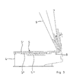
- FIG. 3 10 shows a sectional view of a pressure relief device with a pressure relief flap 5, which consists of three layers 5 ', 5 ", 5"' of the honeycomb material. The layers are superimposed in regions, so that a pyramid-like shape is formed. By using multiple layers of material, it is possible to target the pressure relief flap there amplify where the load on the pressure relief flap in the event of an explosion is large.
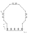
- FIG. 4 is a plan view along a circumference 9 polygonal pressure relief flap with three pressure relief flap closures 10 is shown.
- the pressure relief flap closures 10 are attached to the flap frame, not shown.
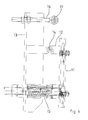
- FIG. 5 shows a side view of a pressure relief flap restraint.
- the pressure relief flap retaining device has a hinge plate 11 which can be connected, for example, with a flap frame, not shown.
- a hinge bearing rod 12 is attached on the hinge plate 11.
- a hinge rod 13 is rotatably connected about the axis 14.
- a hinge spring 15 is also attached on the hinge plate 11. This hinge spring 15 exerts a force in the direction of the hinge rod 13, so that the pressure relief flap clamping device 16 is pressed via the hinge bearing rod 12 in the direction of the hinge plate 11.
- the pressure relief flap clamping device 16 has a rotatably mounted hinge roller 17. In the normal state, this hinge roller 17 presses a pressure relief flap, not shown, on the flap frame.
- FIG. 6 shows a section of a pressure relief flap restraint.
- a hinge rod 18 is actuated by means of a left hinge spring 19 and a right hinge spring 20 via a hinge bearing rod 21.
- the hinge plate 22 is formed arcuate in this embodiment.
- FIG. 7 a silo 23 is shown.
- a pressure relief device 24 are each mounted on top and side by way of example.
- closed systems are secured for cost reasons by rupture disks, which are destroyed in the event of an explosion. Due to the cost-effective production of the presented pressure relief device, the laterally attachable pressure relief device is an alternative to such rupture discs.
Landscapes
- Engineering & Computer Science (AREA)
- General Engineering & Computer Science (AREA)
- Mechanical Engineering (AREA)
- Safety Valves (AREA)
- Pressure Vessels And Lids Thereof (AREA)
Applications Claiming Priority (1)
| Application Number | Priority Date | Filing Date | Title |
|---|---|---|---|
| DE102010016725A DE102010016725A1 (de) | 2010-04-30 | 2010-04-30 | Druckentlastungsvorrichtung |
Publications (2)
| Publication Number | Publication Date |
|---|---|
| EP2383207A2 true EP2383207A2 (fr) | 2011-11-02 |
| EP2383207A3 EP2383207A3 (fr) | 2011-12-28 |
Family
ID=44260916
Family Applications (1)
| Application Number | Title | Priority Date | Filing Date |
|---|---|---|---|
| EP11164110A Withdrawn EP2383207A3 (fr) | 2010-04-30 | 2011-04-28 | Dispositif de décharge de pression |
Country Status (2)
| Country | Link |
|---|---|
| EP (1) | EP2383207A3 (fr) |
| DE (2) | DE102010016725A1 (fr) |
Cited By (2)
| Publication number | Priority date | Publication date | Assignee | Title |
|---|---|---|---|---|
| EP3292330A1 (fr) * | 2015-05-04 | 2018-03-14 | M. Braun Inertgas-Systeme GmbH | Soupape de transfert |
| DE202018103945U1 (de) * | 2018-07-10 | 2019-05-23 | Thorwesten Vent Gmbh | Vorrichtung für geschlossene Systeme zum Ausgleich von Druckstößen |
Families Citing this family (1)
| Publication number | Priority date | Publication date | Assignee | Title |
|---|---|---|---|---|
| DE102015116228A1 (de) | 2014-09-29 | 2016-03-31 | Rembe Gmbh Safety + Control | Berstscheibe |
Citations (2)
| Publication number | Priority date | Publication date | Assignee | Title |
|---|---|---|---|---|
| EP0232478B1 (fr) | 1986-02-05 | 1990-10-17 | Albert Thorwesten | Dispositif pour équilibrer des ondes de pression dans des systèmes fermés par exemple des conduites de transport ou analogues |
| DE202006018244U1 (de) | 2006-12-01 | 2008-04-10 | Thorwesten Vent Gmbh | Vorrichtung zum Ausgleich von Druckstößen in geschlossenen Systemen, wie Silos o.dgl. |
Family Cites Families (3)
| Publication number | Priority date | Publication date | Assignee | Title |
|---|---|---|---|---|
| US4635979A (en) * | 1984-06-11 | 1987-01-13 | Aero Transportation Products, Inc. | Latch device for railcar hatch covers |
| WO2005015119A1 (fr) * | 2003-08-08 | 2005-02-17 | Vanguard Protective Technologies Inc. | Panneaux et conteneurs a l'epreuve du souffle |
| WO2009017459A1 (fr) * | 2007-07-31 | 2009-02-05 | Kai Chye Stephen Seow | Structure de soupape casse-vide |
-
2010
- 2010-04-30 DE DE102010016725A patent/DE102010016725A1/de not_active Withdrawn
-
2011
- 2011-04-28 EP EP11164110A patent/EP2383207A3/fr not_active Withdrawn
- 2011-04-28 DE DE202011110078U patent/DE202011110078U1/de not_active Expired - Lifetime
Patent Citations (2)
| Publication number | Priority date | Publication date | Assignee | Title |
|---|---|---|---|---|
| EP0232478B1 (fr) | 1986-02-05 | 1990-10-17 | Albert Thorwesten | Dispositif pour équilibrer des ondes de pression dans des systèmes fermés par exemple des conduites de transport ou analogues |
| DE202006018244U1 (de) | 2006-12-01 | 2008-04-10 | Thorwesten Vent Gmbh | Vorrichtung zum Ausgleich von Druckstößen in geschlossenen Systemen, wie Silos o.dgl. |
Cited By (2)
| Publication number | Priority date | Publication date | Assignee | Title |
|---|---|---|---|---|
| EP3292330A1 (fr) * | 2015-05-04 | 2018-03-14 | M. Braun Inertgas-Systeme GmbH | Soupape de transfert |
| DE202018103945U1 (de) * | 2018-07-10 | 2019-05-23 | Thorwesten Vent Gmbh | Vorrichtung für geschlossene Systeme zum Ausgleich von Druckstößen |
Also Published As
| Publication number | Publication date |
|---|---|
| DE102010016725A1 (de) | 2011-11-03 |
| EP2383207A3 (fr) | 2011-12-28 |
| DE202011110078U1 (de) | 2012-10-09 |
Similar Documents
| Publication | Publication Date | Title |
|---|---|---|
| WO2015177148A1 (fr) | Dispositif de verrouillage pour portes louvoyantes-coulissantes de véhicules de transport public ; porte louvoyante-coulissante équipée d'un dispositif de verrouillage | |
| DE102013104144A1 (de) | Türaufbau mit einem die Türentriegelung verhindernden Sperrelement | |
| EP2383207A2 (fr) | Dispositif de décharge de pression | |
| DE10310952A1 (de) | Schutzvorrichtung für gepanzerte Fahrzeuge, insbesondere gegen Hohlladungsgeschosse | |
| DE102011109310A1 (de) | Vorrichtung zur Verringerung des Innendrucks in einem Batteriegehäuse | |
| DE102006030174B4 (de) | Explosionsschutzklappe | |
| DE102012104526A1 (de) | Vorrichtung zur explosionstechnischen Entkopplung zweier Anlagenteile | |
| DE102009040409A1 (de) | Scharnier und Verfahren zum Betreiben eines Scharniers | |
| WO2014048410A2 (fr) | Serrure pour un ouvrant ou une porte | |
| WO2015110649A2 (fr) | Conteneur, en particulier benne amovible, benne à vider ou à rouler | |
| DE3140043C2 (de) | Brandschutzklappe | |
| DE102011075267A1 (de) | Scharniereinrichtung für eine Frontklappe eines Kraftfahrzeugs, die in eine Fußgängerschutzlage hochstellbar ist | |
| DE102011009117A1 (de) | Fahrzeugtürsicherheitseinrichtung | |
| EP2125305B1 (fr) | Machine de coupe à levier | |
| DE102016003691A1 (de) | Tür, insbesondere Seitentür, für ein Sonderschutzfahrzeug | |
| EP2334511B1 (fr) | Dispositif de fermeture pour une ouverture d'entrée d'un réservoir de carburant déplaçable | |
| DE102010041704A1 (de) | Regelventil zur Regelung eines Volumenstromes | |
| EP2744624B1 (fr) | Dispositif d'actionnement | |
| DE102014001793A1 (de) | Abdeckung für Überrollkörper | |
| DE102007041387A1 (de) | Bremsvorrichtung für eine Cockpittür zum Bremsen im Dekompressionsfall | |
| DE202012101668U1 (de) | Presscontainer | |
| DE2651824C2 (de) | Verschluß für eine verschwenkbare Sicherheitsklappe, insbesondere an einem Kraftwerksgebäude | |
| DE102008032542A1 (de) | Kraftfahrzeug | |
| DE102007043885A1 (de) | Zellradschleuse | |
| DE102017114356B4 (de) | Schwenkeinheit zum Schwenken von Anbauteilen oder Werkstücken |
Legal Events
| Date | Code | Title | Description |
|---|---|---|---|
| AK | Designated contracting states |
Kind code of ref document: A2 Designated state(s): AL AT BE BG CH CY CZ DE DK EE ES FI FR GB GR HR HU IE IS IT LI LT LU LV MC MK MT NL NO PL PT RO RS SE SI SK SM TR |
|
| AX | Request for extension of the european patent |
Extension state: BA ME |
|
| PUAI | Public reference made under article 153(3) epc to a published international application that has entered the european phase |
Free format text: ORIGINAL CODE: 0009012 |
|
| PUAL | Search report despatched |
Free format text: ORIGINAL CODE: 0009013 |
|
| AK | Designated contracting states |
Kind code of ref document: A3 Designated state(s): AL AT BE BG CH CY CZ DE DK EE ES FI FR GB GR HR HU IE IS IT LI LT LU LV MC MK MT NL NO PL PT RO RS SE SI SK SM TR |
|
| AX | Request for extension of the european patent |
Extension state: BA ME |
|
| RIC1 | Information provided on ipc code assigned before grant |
Ipc: B65D 90/32 20060101ALI20111121BHEP Ipc: B65D 90/62 20060101ALI20111121BHEP Ipc: B65D 90/34 20060101AFI20111121BHEP |
|
| STAA | Information on the status of an ep patent application or granted ep patent |
Free format text: STATUS: THE APPLICATION IS DEEMED TO BE WITHDRAWN |
|
| 18D | Application deemed to be withdrawn |
Effective date: 20120629 |