EP2383438B1 - Aube en superalliage monocristallin - Google Patents
Aube en superalliage monocristallin Download PDFInfo
- Publication number
- EP2383438B1 EP2383438B1 EP11163618.9A EP11163618A EP2383438B1 EP 2383438 B1 EP2383438 B1 EP 2383438B1 EP 11163618 A EP11163618 A EP 11163618A EP 2383438 B1 EP2383438 B1 EP 2383438B1
- Authority
- EP
- European Patent Office
- Prior art keywords
- blade
- side wall
- tip
- cladding layer
- single crystal
- Prior art date
- Legal status (The legal status is an assumption and is not a legal conclusion. Google has not performed a legal analysis and makes no representation as to the accuracy of the status listed.)
- Active
Links
Images


Classifications
-
- F—MECHANICAL ENGINEERING; LIGHTING; HEATING; WEAPONS; BLASTING
- F01—MACHINES OR ENGINES IN GENERAL; ENGINE PLANTS IN GENERAL; STEAM ENGINES
- F01D—NON-POSITIVE DISPLACEMENT MACHINES OR ENGINES, e.g. STEAM TURBINES
- F01D5/00—Blades; Blade-carrying members; Heating, heat-insulating, cooling or antivibration means on the blades or the members
- F01D5/12—Blades
- F01D5/28—Selecting particular materials; Particular measures relating thereto; Measures against erosion or corrosion
-
- C—CHEMISTRY; METALLURGY
- C30—CRYSTAL GROWTH
- C30B—SINGLE-CRYSTAL GROWTH; UNIDIRECTIONAL SOLIDIFICATION OF EUTECTIC MATERIAL OR UNIDIRECTIONAL DEMIXING OF EUTECTOID MATERIAL; REFINING BY ZONE-MELTING OF MATERIAL; PRODUCTION OF A HOMOGENEOUS POLYCRYSTALLINE MATERIAL WITH DEFINED STRUCTURE; SINGLE CRYSTALS OR HOMOGENEOUS POLYCRYSTALLINE MATERIAL WITH DEFINED STRUCTURE; AFTER-TREATMENT OF SINGLE CRYSTALS OR A HOMOGENEOUS POLYCRYSTALLINE MATERIAL WITH DEFINED STRUCTURE; APPARATUS THEREFOR
- C30B11/00—Single-crystal growth by normal freezing or freezing under temperature gradient, e.g. Bridgman-Stockbarger method
-
- C—CHEMISTRY; METALLURGY
- C30—CRYSTAL GROWTH
- C30B—SINGLE-CRYSTAL GROWTH; UNIDIRECTIONAL SOLIDIFICATION OF EUTECTIC MATERIAL OR UNIDIRECTIONAL DEMIXING OF EUTECTOID MATERIAL; REFINING BY ZONE-MELTING OF MATERIAL; PRODUCTION OF A HOMOGENEOUS POLYCRYSTALLINE MATERIAL WITH DEFINED STRUCTURE; SINGLE CRYSTALS OR HOMOGENEOUS POLYCRYSTALLINE MATERIAL WITH DEFINED STRUCTURE; AFTER-TREATMENT OF SINGLE CRYSTALS OR A HOMOGENEOUS POLYCRYSTALLINE MATERIAL WITH DEFINED STRUCTURE; APPARATUS THEREFOR
- C30B29/00—Single crystals or homogeneous polycrystalline material with defined structure characterised by the material or by their shape
- C30B29/10—Inorganic compounds or compositions
- C30B29/52—Alloys
-
- F—MECHANICAL ENGINEERING; LIGHTING; HEATING; WEAPONS; BLASTING
- F01—MACHINES OR ENGINES IN GENERAL; ENGINE PLANTS IN GENERAL; STEAM ENGINES
- F01D—NON-POSITIVE DISPLACEMENT MACHINES OR ENGINES, e.g. STEAM TURBINES
- F01D5/00—Blades; Blade-carrying members; Heating, heat-insulating, cooling or antivibration means on the blades or the members
- F01D5/12—Blades
- F01D5/28—Selecting particular materials; Particular measures relating thereto; Measures against erosion or corrosion
- F01D5/288—Protective coatings for blades
-
- F—MECHANICAL ENGINEERING; LIGHTING; HEATING; WEAPONS; BLASTING
- F05—INDEXING SCHEMES RELATING TO ENGINES OR PUMPS IN VARIOUS SUBCLASSES OF CLASSES F01-F04
- F05C—INDEXING SCHEME RELATING TO MATERIALS, MATERIAL PROPERTIES OR MATERIAL CHARACTERISTICS FOR MACHINES, ENGINES OR PUMPS OTHER THAN NON-POSITIVE-DISPLACEMENT MACHINES OR ENGINES
- F05C2201/00—Metals
- F05C2201/04—Heavy metals
- F05C2201/0433—Iron group; Ferrous alloys, e.g. steel
- F05C2201/0466—Nickel
-
- F—MECHANICAL ENGINEERING; LIGHTING; HEATING; WEAPONS; BLASTING
- F05—INDEXING SCHEMES RELATING TO ENGINES OR PUMPS IN VARIOUS SUBCLASSES OF CLASSES F01-F04
- F05D—INDEXING SCHEME FOR ASPECTS RELATING TO NON-POSITIVE-DISPLACEMENT MACHINES OR ENGINES, GAS-TURBINES OR JET-PROPULSION PLANTS
- F05D2230/00—Manufacture
- F05D2230/90—Coating; Surface treatment
-
- F—MECHANICAL ENGINEERING; LIGHTING; HEATING; WEAPONS; BLASTING
- F05—INDEXING SCHEMES RELATING TO ENGINES OR PUMPS IN VARIOUS SUBCLASSES OF CLASSES F01-F04
- F05D—INDEXING SCHEME FOR ASPECTS RELATING TO NON-POSITIVE-DISPLACEMENT MACHINES OR ENGINES, GAS-TURBINES OR JET-PROPULSION PLANTS
- F05D2240/00—Components
- F05D2240/20—Rotors
- F05D2240/30—Characteristics of rotor blades, i.e. of any element transforming dynamic fluid energy to or from rotational energy and being attached to a rotor
- F05D2240/307—Characteristics of rotor blades, i.e. of any element transforming dynamic fluid energy to or from rotational energy and being attached to a rotor related to the tip of a rotor blade
-
- F—MECHANICAL ENGINEERING; LIGHTING; HEATING; WEAPONS; BLASTING
- F05—INDEXING SCHEMES RELATING TO ENGINES OR PUMPS IN VARIOUS SUBCLASSES OF CLASSES F01-F04
- F05D—INDEXING SCHEME FOR ASPECTS RELATING TO NON-POSITIVE-DISPLACEMENT MACHINES OR ENGINES, GAS-TURBINES OR JET-PROPULSION PLANTS
- F05D2300/00—Materials; Properties thereof
- F05D2300/10—Metals, alloys or intermetallic compounds
- F05D2300/13—Refractory metals, i.e. Ti, V, Cr, Zr, Nb, Mo, Hf, Ta, W
- F05D2300/134—Zirconium
-
- F—MECHANICAL ENGINEERING; LIGHTING; HEATING; WEAPONS; BLASTING
- F05—INDEXING SCHEMES RELATING TO ENGINES OR PUMPS IN VARIOUS SUBCLASSES OF CLASSES F01-F04
- F05D—INDEXING SCHEME FOR ASPECTS RELATING TO NON-POSITIVE-DISPLACEMENT MACHINES OR ENGINES, GAS-TURBINES OR JET-PROPULSION PLANTS
- F05D2300/00—Materials; Properties thereof
- F05D2300/10—Metals, alloys or intermetallic compounds
- F05D2300/14—Noble metals, i.e. Ag, Au, platinum group metals
- F05D2300/143—Platinum group metals, i.e. Os, Ir, Pt, Ru, Rh, Pd
-
- F—MECHANICAL ENGINEERING; LIGHTING; HEATING; WEAPONS; BLASTING
- F05—INDEXING SCHEMES RELATING TO ENGINES OR PUMPS IN VARIOUS SUBCLASSES OF CLASSES F01-F04
- F05D—INDEXING SCHEME FOR ASPECTS RELATING TO NON-POSITIVE-DISPLACEMENT MACHINES OR ENGINES, GAS-TURBINES OR JET-PROPULSION PLANTS
- F05D2300/00—Materials; Properties thereof
- F05D2300/60—Properties or characteristics given to material by treatment or manufacturing
- F05D2300/607—Monocrystallinity
-
- F—MECHANICAL ENGINEERING; LIGHTING; HEATING; WEAPONS; BLASTING
- F05—INDEXING SCHEMES RELATING TO ENGINES OR PUMPS IN VARIOUS SUBCLASSES OF CLASSES F01-F04
- F05D—INDEXING SCHEME FOR ASPECTS RELATING TO NON-POSITIVE-DISPLACEMENT MACHINES OR ENGINES, GAS-TURBINES OR JET-PROPULSION PLANTS
- F05D2300/00—Materials; Properties thereof
- F05D2300/60—Properties or characteristics given to material by treatment or manufacturing
- F05D2300/611—Coating
-
- Y—GENERAL TAGGING OF NEW TECHNOLOGICAL DEVELOPMENTS; GENERAL TAGGING OF CROSS-SECTIONAL TECHNOLOGIES SPANNING OVER SEVERAL SECTIONS OF THE IPC; TECHNICAL SUBJECTS COVERED BY FORMER USPC CROSS-REFERENCE ART COLLECTIONS [XRACs] AND DIGESTS
- Y02—TECHNOLOGIES OR APPLICATIONS FOR MITIGATION OR ADAPTATION AGAINST CLIMATE CHANGE
- Y02T—CLIMATE CHANGE MITIGATION TECHNOLOGIES RELATED TO TRANSPORTATION
- Y02T50/00—Aeronautics or air transport
- Y02T50/60—Efficient propulsion technologies, e.g. for aircraft
Definitions
- the inventive subject matter generally relates to turbines, and more particularly relates to turbine blades and assemblies.
- Gas turbine engines such as turbofan gas turbine engines, may be used to power various types of vehicles and systems, such as aircraft.
- these engines include turbines that rotate at a high speed when blades (or airfoils) extending therefrom are impinged by high-energy compressed air. Consequently, the blades are subjected to high heat and stress loadings which, over time, may reduce their structural integrity.
- a blade cooling scheme can be included to provide active cooling of the blade and to maintain the blade temperatures within acceptable limits.
- the blade cooling scheme directs cooling air through an internal cooling circuit formed in the blade.
- the internal cooling circuit may include a simple channel extending through a length of the blade or may consist of a series of connected, serpentine cooling passages, which incorporate raised or depressed structures therein.
- the serpentine cooling passages increase the cooling effectiveness by extending the length of the air flow path.
- the blade may have multiple internal walls that form intricate passages through which the cooling air flows to feed the serpentine cooling passages.
- EP EP2138612 discloses single crystal nickel-based superalloy compositions and methods of fabricating such components.
- EP0559330 discloses a ceramic article for use at high temperatures and in corrosive environments comprising a ceramic substrate on which is deposited a substantially non-porous coating of one or more precious metals or alloys thereof.
- EP1258598 discloses a sequenced manufacturing process for turbine airfoils which are assembled into the dovetail slots of a turbine disk.
- US7645123 discloses a turbine blade having a squealer tip rail forming a squealer pocket on the blade tip, and a row of blade tip peripheral film cooling holes on the pressure side and suction side of the blade for cooling the blade tip rails.
- Blades for turbines, turbine blade assemblies, and methods of forming blades are provided according to the claims.
- a blade includes an airfoil including a convex suction side wall, a concave pressure side wall, a leading edge, a trailing edge, a root, and a tip, the convex suction side wall, the concave pressure side wall, and the tip each including interior surfaces that together define an internal cooling circuit, the airfoil comprising a single crystal superalloy, and a cladding layer disposed over the tip, the cladding layer a comprising a zirconia grain stabilized platinum alloy.
- a turbine blade assembly includes a turbine including a hub and a plurality of blades extending from the hub and a shroud disposed around the turbine.
- Each blade includes an airfoil including a convex suction side wall, a concave pressure side wall, a leading edge, a trailing edge, a root, and a tip, the convex suction side wall, the concave pressure side wall, and the tip each including an interior surface defining an internal cooling circuit, the airfoil comprising a single crystal superalloy, and a cladding layer disposed over the tip, the cladding layer comprising a zirconia grain stabilized platinum alloy.
- a method for forming a blade includes disposing a cladding layer over a tip of a blade airfoil, the cladding layer having an initial thickness and comprising a zirconia grain stabilized platinum alloy, and the blade airfoil comprising a single crystal superalloy, and machining the cladding layer to a final desired thickness.
- An improved blade is provided that may be implemented into components subjected to temperatures of 1150 °C or greater.
- the blade includes a tip to which a cladding layer may be diffusion bonded.
- the cladding layer is formulated to provide creep-resistance to the blade and, in this regard, may be formed from a platinum alloy.
- a suitable platinum alloy includes, but is not limited to, a zirconia grain stabilized platinum alloy.
- the improved blade may be incorporated into first stage turbine assemblies or in any other sections of an engine. Although described as being implemented as a part of a turbofan gas turbine engine, the blade alternatively may be included in other types of engines.
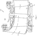
- FIG. 1 is a cross-sectional side view of a portion of a turbine section 100 of an engine, according to an embodiment.
- the turbine section 100 receives high temperature gases (e.g., gases having a temperature greater than 1100 °C) from an upstream engine combustor (not shown) to produce energy for the engine and/or components coupled to the engine.
- the turbine section 100 includes a turbine nozzle 104 that has a plurality of static vanes 106 mounted circumferentially around a ring 108. The static vanes 106 direct the gases from the combustor to a turbine rotor 110.
- the turbine rotor 110 includes a plurality of blades 112 (only one of which is shown) that are attached to a hub 114 and retained in axial position by a retention plate 116. When the blades 112 are impinged upon by the gases, the gases cause the turbine rotor 110 to spin.
- an outer circumferential wall 118 surrounds the static vanes 106 and the plurality of blades 112 to define a flowpath 122.
- the outer circumferential wall 118 can include a first annular section 122 disposed around the static vanes 106 and a shroud 124 surrounding the plurality of blades 112, in an embodiment.
- the outer circumferential wall 118 defines a portion of a compressor discharge plenum 120 that is disposed radially outwardly relative to the flowpath 122.
- the compressor discharge plenum 120 receives bleed air from a compressor section (not shown), which may be directed through one or more openings in the outer circumferential wall 118 towards the plurality of blades 112 to cool the blades 112.
- FIG. 2 is a perspective view of a blade 200, according to an embodiment.
- the blade 200 may be implemented into a turbine rotor (e.g., turbine rotor 110 in FIG. 1 ) and includes a blade attachment section 202, an airfoil 204, and a platform 206.
- the blade attachment section 202 provides an area in which a shape is machined.
- the shape corresponds with a shape formed in a respective blade attachment slot (not shown) of the turbine hub (e.g., hub 114 in FIG. 1 ).
- the shape may be a firtree shape.
- the shape may be a beveled shape.
- any one of numerous other shapes suitable for attaching the blade 200 to the turbine may be alternatively machined therein.
- the airfoil 204 has a root 208 and two outer walls 210, 212.
- the root 208 is attached to the platform 206 and is integrally formed with each outer wall 210, 212.
- the outer walls 210, 212 have outer surfaces that define an airfoil shape.
- the airfoil shape includes a leading edge 214, a trailing edge 216, a pressure side 218 along the first concave outer wall 210, a suction side 220 along the second convex outer wall 212, a tip 222, a pressure side discharge trailing edge slot 224, and an airfoil platform fillet 226.
- the tip 222 serves as a wall that extends between the concave pressure side wall 210 and the convex suction side wall 212.
- a parapet 228 extends from the tip 222 to form a well 230 with a top surface of the tip 222.
- the parapet 228 may be configured to extend substantially parallel to the concave pressure side wall 210 and the convex suction side wall 212 beyond the tip 222 a particular height.
- the parapet 228 extends an entire length of one or both of the concave pressure side wall 210 and the convex suction side wall 212.
- the parapet 228 may extend a portion of the lengths of one or both of the concave pressure side wall 210 and the convex suction side wall 212.
- the parapet 228 may have height in a range of about 0.38 mm to about 1.14 mm, in an embodiment. In other embodiments, the height may be greater or less than the aforementioned range. Although depicted as substantially uniform in height, the parapet 228 may be shorter at some locations than at others.
- the blade 200 may be actively cooled by an internal cooling circuit formed therein.
- the internal cooling circuit may extend from an opening in the platform 206 through the blade 200 and may include various passages that eventually communicate with the trailing edge slot 224 or other openings that may be formed in the blade 200.
- the convex suction side wall 212, the concave pressure side wall 210, and the tip 222 each include interior surfaces defining the internal cooling circuit.
- the blade 200 comprises a single crystal superalloy material.
- a "single crystal superalloy material” may be defined as a superalloy material formed to have a single crystallographic orientation throughout its entirety and to be substantially free of high angle boundaries.
- an incidental amount of low angle boundaries which are commonly defined as the boundaries between adjacent grains whose crystallographic orientation differs by less than about 5 degrees, such as tilt or twist boundaries, may be present within the single crystal superalloy material after solidification and formation of the single crystal superalloy material, or after some deformation of the component during creep or other deformation process.
- low angle boundaries are not present in the single crystal superalloy component.
- the single crystal superalloy material may be composed of, but is not limited to, a base material, such as a nickel-based superalloy, in an embodiment.
- a nickel-based superalloy include, but are not limited to, MAR-M-247EA, MAR-M-247DS or SC180.
- the blade 200 may comprise a different base material, such as a cobalt-based superalloy.
- the blade 200 may be cast as an equiaxed, directionally solidified, or single crystal blade.
- the blade 200 includes one or more coatings to reduce thermal mechanical fatigue resulting from cyclic and prolonged exposure to the high temperatures. According to an embodiment, an entirety of the blade 200 can be substantially uniformly covered with one or more coatings. In another embodiment, certain portions of the blade 200 include different coatings tailored to provide particular desired properties to the blade 200.
- the pressure side wall 210 and the suction side wall 212 may include a first set of coatings formulated to provide oxidation resistance properties and to form a thermal conductivity barrier for maintaining temperatures low in concert with the temperature of the cooling gas flowing through the internal cooling circuit, while the tip 222 includes a second set of coatings formulated primarily to provide creep resistance properties as well as oxidation resistance.
- FIGs. 3 and 4 are cross section views of the pressure side wall 210 of the blade 200 of FIG. 2 taken along line 3-3 and the tip 222 of the blade 200 of FIG. 2 taken along line 4-4, according to an embodiment.
- the pressure side wall 210 may include a bond coating 234, a thermal barrier coating 236, and one or more intermediate layers 238 (shown in phantom).
- the coatings and layers 234, 236, 238 are described in conjunction with the pressure side wall 210, it will be appreciated that the same may be applied to the suction side wall 212 and other portions of the blade 200, including but not limited to the leading edge 214 and the trailing edge 216 of the blade 200.
- the coatings and layers 234, 236, 238 are disposed over a base material 248.
- the base material 248 is selected from one or more of the single crystal superalloy material mentioned previously.
- the bond coating 234 is included to provide improved adherence of the thermal barrier coating 236 to the base material 248.
- the bond coating 234 comprises a diffusion aluminide coating that is formed by depositing an aluminum layer over the component blade, and by interdiffusing the aluminum layer with the superalloy substrate.
- the bond coating is a simple diffusion aluminide.
- the bond coating is a more complex diffusion aluminide that includes other metallic layers.
- the other metallic layer is a platinum layer.
- the other metallic layer is a hafnium and/or a zirconium layer. In yet another embodiment, the other metallic layer is a co-deposited hafnium, zirconium, and platinum layer.
- the bond coating 234 is an overlay coating known as an MCrAlX coating, wherein M is cobalt, nickel, or combinations thereof.
- the X is hafnium, zirconium, yttrium, tantalum, rhenium, ruthenium, palladium, platinum, silicon, or combinations thereof.
- Some examples of MCrAlX compositions include NiCoCrAlY and CoNiCrAlY.
- the bond coating 234 is a combination of two types of bond coatings, a diffusion aluminide coating formed on an MCrA1X coating.
- Thermal barrier coating 236 protects the blade 200 from the extremely high temperatures.
- Thermal barrier coating 236 may comprise, for example, a partially stabilized zirconia-based thermal barrier coating, such as yttria stabilized zirconia (YSZ).
- YSZ yttria stabilized zirconia
- intermediate layers 238 may be included between the bond coating 234 and the thermal barrier coating 236.
- the thermal barrier coating 236 is not included over the tip 222, in an embodiment.
- the intermediate layers 238 can be formulated to reduce the effect of impurities in the bond coating 234 and to minimize the growth of oxides on the bond coating 234 to thereby improve the adherence of the thermal barrier coating 236 to the bond coating 234 and reduce thermal mismatch stress due to growth of an alumina scale.
- the tip 222 comprises the base material 248 and a cladding layer 250, as shown in FIG. 4 .
- the base material 248 is formed from the single crystal superalloy material mentioned above in relation to the blade 200 and includes the cladding layer 250 disposed thereover, in an embodiment.
- the cladding layer 250 is formulated to have improved creep resistance and stress properties over those of the base material 248 as portions of the tip 222, such as the parapet 224, may not be actively cooled by the internal cooling circuit resulting in undesirably higher temperatures and may be more susceptible to unwanted deformation resulting from creep.
- the cladding layer 250 comprises a platinum alloy having a coefficient of thermal expansion that is lower than a coefficient of thermal expansion of the base material 248.
- the ZGS platinum alloy of the cladding layer 250 maintains structural integrity at temperatures above 1150 °C, while the base material 248 resists creep at the cooled lower temperatures.
- the ZGS platinum alloy of the cladding layer 250 protects the base material 248 from deformation to resist creeping, due to the lower coefficient of thermal expansion of the ZGS platinum alloy. Specifically, the ZGS platinum alloy does not expand as quickly as the base material 248 and, thus does not impart as much of a strain on the base material as compared to other materials at the elevated temperatures.
- ZGS platinum alloys are oxide dispersion strengthened (ODS) and include up to about 1.0%, by weight, of zirconium oxide or zirconium oxide and yttrium oxide.
- ODS ZGS platinum alloys may comprise one or more additional elements, including but not limited to rhodium, iridium, aluminum, chromium, ruthenium, cobalt, and nickel.
- the one or more additional elements may be present at about 10% by weight.
- the one or more additional elements can also increase creep resistance by solid solution strengthening or by the forming intermetallic precipitates.
- the cladding layer 250 has a thickness in a range of about 0.1 mm to about 0.7 mm, in an embodiment. In other embodiments, the cladding layer 250 may be thicker or thinner than the aforementioned range.
- a bond coating 252 may be included between the cladding layer 250 and the base material 248 to provide improved adhesion of the cladding layer 250 to the base material 258, in an embodiment.
- the bond coating 252 may be formed from a noble metal, including but not limited to platinum, palladium, and ruthenium.
- the bond coating 252 has a thickness in a range of about 0.006 mm to about 0.05 mm, in an embodiment. In another embodiment, the bond coating 252 may be thicker or thinner than the aforementioned range.
- FIG. 5 is a flow diagram of a method 500 of forming the cladding layer 250 over the blade 200, according to an embodiment.
- the method 500 includes forming a blade airfoil from a single crystal superalloy material, step 502.
- the single crystal superalloy material may comprise a base material having a formulation that is substantially similar to base material 248 of blade 200 described above.
- vacuum-induction melting and casting processes may be used.
- a thermal gradient solidification method may be employed.
- molten metal having a composition of the base material e.g., a metal, such as a nickel-based superalloy
- a heat resistant ceramic mold having a shape corresponding to that of the final fabricated component.
- the desired shape of the final fabricated component may be a blade airfoil.
- the mold and molten metal contained therein are placed in a furnace, induction heating coil or other heating device to melt the metal, and the mold and molten metal are gradually cooled.
- metal adjacent a cooler end of the mold initially solidifies, and an interface between the solidified and liquid metal gradually moves through the metal as cooling continues.
- Thermal gradient solidification can be performed by placing a chill block adjacent one end of the mold and then turning off the heat source to allow the mold and molten metal to cool and solidify in a controlled desirable temperature gradient. Alternatively, the mold and molten metal can be gradually withdrawn from the heat source.
- the thermal gradient solidification process causes certain crystallographic orientations such as ⁇ 001> to grow to the exclusion of other crystallographic orientations so that a single grain becomes dominant throughout the blade airfoil.
- Techniques may be employed to promote the formation of the single crystal orientation. For example, an oriented single crystal starting material can be positioned adjacent the metal first solidified so that the metal initially develops that orientation. In other embodiments, other techniques for forming the base material into the single crystal superalloy material may be used.
- a liquid metal cooling process or casting process may be used to fabricate the airfoil.
- the base material is melted and poured into a ceramic mold placed inside a multi-zone heater.
- the cast components are immersed at a constant rate into a liquid tin bath.
- the bond coating may include a precious metal, such as platinum, palladium, or ruthenium.
- the bond coating comprises pure platinum.
- the term "pure platinum” may be defined as platinum having a purity of greater than about 99%.
- the bond coating is applied directly to the surface of the blade airfoil.
- the bond coating may be applied to the blade airfoil by a plating process. For example, electroplating, electroless plating or other plating processes may be employed.
- the bond coating may be deposited by a deposition process, such as by laser deposition, and the like.
- the bond coating may be applied to the tip by a sputtering process.
- the bond coating may be applied to a thickness in a range of from about 6 ⁇ m to about 14 ⁇ m, in an embodiment.
- the bond coating may be thicker or thinner than the aforementioned range.
- the bond coating may be applied to other portions of the blade in preparation of forming other coatings, such as thermal barrier coatings or intermediate layers (e.g., thermal barrier coating 236 or intermediate layer 238), in other embodiments.
- the cladding layer comprises one or more of the platinum alloys as described above in relation to cladding layer 250.
- the cladding layer is formed from the ZGS platinum alloy.
- the ZGS platinum alloy may be obtained as a sheet and machined to desired dimensions.
- the sheet may be selected for a thickness that is greater than a final desired thickness of the cladding layer.
- the thickness of the sheet may be in a range of about 0.2 mm to about 0.5 mm. In other embodiments, the sheet thickness may be greater or less than the aforementioned range.
- the sheet may be machined or cut to have a particular area depending on an area of the blade airfoil to be covered.
- the ZGS platinum alloy sheet is bonded to the bond coating.
- the sheet is diffusion bonded to the base material.
- surfaces of the airfoil are cleaned to thereby remove contaminants, such as oxides, that may disrupt or interfere with the bonding.
- the cleaned airfoil is then contacted with the ZGS platinum alloy sheet, and a vacuum seal is affected therebetween.
- the two are held under a hot isostatic pressure load at an elevated temperature.
- Suitable pressures which may be applied to the airfoil and the sheet are in a range of about 15 to about 30 ksi.
- Suitable temperatures which may be employed for the diffusion bonding process may be in a range of between about 1035°C to about 1110° C.
- Other forms of diffusion bonding may alternatively be employed such as by the application of an axial force in a vacuum atmosphere.
- the cladding layer is machined to a final desired thickness and shape, step 508.
- one or more blades are attached to a hub.
- the hub is positioned within a ring having an inner diameter that is substantially equal to a desired inner diameter dimension of a shroud component within which the blade will be disposed.
- the inner diameter of the ring may be slightly greater than a largest diameter of the hub measured from blade to blade.
- the hub is rotated at a speed that is equal to or greater than a speed at which the blade may be rotated when disposed in an engine.
- the tip of the blade airfoil is abraded by an inner surface of the ring resulting in the final desired thickness of the cladding layer.
- grinding or another machining process may be employed to obtain the final desired thickness of the cladding layer.
- the blade airfoil may undergo further coating processes, in an embodiment. In other embodiments, the blade airfoil may be readied for inclusion into an engine component.
- improved blades suitable for use in operating temperatures greater than 1150 °C have been provided.
- thermal mechanical fatigue of the blades may be reduced and oxidation resistance improved and service lives of the blades may be improved over those of conventional blades.
- the improved blades may be more creep-resistant than blades formed from traditional superalloy and coating materials.
- the improved blades are relatively simple and inexpensive to manufacture.
Landscapes
- Engineering & Computer Science (AREA)
- Chemical & Material Sciences (AREA)
- Materials Engineering (AREA)
- Crystallography & Structural Chemistry (AREA)
- Metallurgy (AREA)
- Organic Chemistry (AREA)
- Mechanical Engineering (AREA)
- General Engineering & Computer Science (AREA)
- Inorganic Chemistry (AREA)
- Turbine Rotor Nozzle Sealing (AREA)
Claims (7)
- Aube (200), comprenant :un profil aérodynamique (204) comportant une paroi extrados convexe (212), une paroi intrados concave (210), un bord d'attaque (214), un bord de fuite (216), un talon (208) et un bout (222), la paroi extrados convexe (212), la paroi intrados concave (210) et le bout (222) comportant chacun des surfaces intérieures qui, ensemble, définissent un circuit de refroidissement interne, le profil aérodynamique (204) comprenant un superalliage monocristallin ;un premier ensemble de revêtements (234, 236, 238) appliqués par-dessus la paroi intrados (210) et la paroi extrados (212), le premier ensemble de revêtements comportant un revêtement de liaison (234) appliqué par-dessus le superalliage monocristallin de la paroi intrados (210) et de la paroi extrados (212), et un revêtement formant barrière thermique (236) appliqué par-dessus le revêtement de liaison (234) sur la paroi intrados (210) et la paroi extrados (212) ; l'aube étant caractérisée en ce qu'elle comprend en outre :
un deuxième ensemble de revêtements (250, 252) appliqué par-dessus le bout (222), le deuxième ensemble de revêtements (250, 252) étant différent du premier ensemble de revêtements et comportant un revêtement de liaison (252) comprenant un métal noble appliqué par-dessus le superalliage monocristallin du bout (222) et une couche de placage (250) appliquée par-dessus le revêtement de liaison (252) du bout (222), la couche de placage (250) comprenant un alliage de platine stabilisé aux grains de zircone. - Aube (200) selon la revendication 1, dans laquelle le superalliage monocristallin comprend un superalliage à base de nickel.
- Aube (200) selon la revendication 1, dans laquelle la couche de placage (250) présente une épaisseur comprise entre environ 0,1 mm et environ 0,4 mm.
- Aube (200) selon la revendication 1, dans laquelle le bout (222) comporte un parapet (228) et la couche de placage (250) est formée par-dessus le parapet (228).
- Aube (200) selon la revendication 1, dans laquelle la couche de placage (250) est liée par diffusion au bout (222).
- Ensemble aube de turbine, comprenant :une turbine comportant un moyeu (114) et une pluralité d'aubes (112) s'étendant depuis le moyeu (114), chaque aube (112) comprenant l'aube (200) selon la revendication 1 ; etune enveloppe (124) placée autour de la turbine.
- Procédé de formation de l'aube (200) selon la revendication 1, le procédé comprenant les étapes de :liaison par diffusion d'une feuille de la couche de placage (250) par-dessus le revêtement de liaison comprenant le métal noble au niveau du bout (222) du profil aérodynamique (204) de l'aube, la couche de placage (250) présentant une épaisseur initiale ; etusinage de la couche de placage (250) jusqu'à une épaisseur finale souhaitée.
Applications Claiming Priority (1)
| Application Number | Priority Date | Filing Date | Title |
|---|---|---|---|
| US12/771,789 US8535005B2 (en) | 2010-04-30 | 2010-04-30 | Blades, turbine blade assemblies, and methods of forming blades |
Publications (3)
| Publication Number | Publication Date |
|---|---|
| EP2383438A2 EP2383438A2 (fr) | 2011-11-02 |
| EP2383438A3 EP2383438A3 (fr) | 2017-06-14 |
| EP2383438B1 true EP2383438B1 (fr) | 2019-03-27 |
Family
ID=44279806
Family Applications (1)
| Application Number | Title | Priority Date | Filing Date |
|---|---|---|---|
| EP11163618.9A Active EP2383438B1 (fr) | 2010-04-30 | 2011-04-25 | Aube en superalliage monocristallin |
Country Status (2)
| Country | Link |
|---|---|
| US (1) | US8535005B2 (fr) |
| EP (1) | EP2383438B1 (fr) |
Families Citing this family (13)
| Publication number | Priority date | Publication date | Assignee | Title |
|---|---|---|---|---|
| US8371814B2 (en) * | 2009-06-24 | 2013-02-12 | Honeywell International Inc. | Turbine engine components |
| US8529193B2 (en) * | 2009-11-25 | 2013-09-10 | Honeywell International Inc. | Gas turbine engine components with improved film cooling |
| US8628293B2 (en) | 2010-06-17 | 2014-01-14 | Honeywell International Inc. | Gas turbine engine components with cooling hole trenches |
| DE102011081112A1 (de) * | 2011-08-17 | 2013-02-21 | Rolls-Royce Deutschland Ltd & Co Kg | Verfahren zur Herstellung eines Bauteils für hohe thermische Belastungen, ein Bauteil herstellbar mit dem Verfahren und ein Flugzeugtriebwerk mit dem Bauteil |
| US9145775B2 (en) | 2012-03-02 | 2015-09-29 | United Technologies Corporation | Tapered thermal coating for airfoil |
| US9650900B2 (en) | 2012-05-07 | 2017-05-16 | Honeywell International Inc. | Gas turbine engine components with film cooling holes having cylindrical to multi-lobe configurations |
| US10113433B2 (en) | 2012-10-04 | 2018-10-30 | Honeywell International Inc. | Gas turbine engine components with lateral and forward sweep film cooling holes |
| DE102012110750A1 (de) * | 2012-11-09 | 2014-05-15 | Heraeus Materials Technology Gmbh & Co. Kg | Einkristalline Zündelektrode |
| US11021965B2 (en) | 2016-05-19 | 2021-06-01 | Honeywell International Inc. | Engine components with cooling holes having tailored metering and diffuser portions |
| EP3507558A4 (fr) * | 2016-09-01 | 2020-04-22 | Additive Rocket Corporation | Échangeur de chaleur structurel |
| FR3063663B1 (fr) * | 2017-03-13 | 2021-02-26 | Mecachrome France | Procede de fabrication de pieces en alliage metallique de forme complexe |
| CN110662884B (zh) * | 2017-05-30 | 2022-11-18 | 西门子能源全球两合公司 | 具有凹槽尖端和致密的氧化物弥散强化层的涡轮机叶片 |
| US10738644B2 (en) * | 2017-08-30 | 2020-08-11 | General Electric Company | Turbine blade and method of forming blade tip for eliminating turbine blade tip wear in rubbing |
Family Cites Families (16)
| Publication number | Priority date | Publication date | Assignee | Title |
|---|---|---|---|---|
| DE3151413A1 (de) * | 1981-12-24 | 1983-07-14 | MTU Motoren- und Turbinen-Union München GmbH, 8000 München | "schaufel einer stroemungsmaschine, insbesondere gasturbine" |
| GB8629728D0 (en) | 1986-12-12 | 1987-01-21 | Johnson Matthey Plc | Scratch resistant surface layer |
| US5288205A (en) | 1990-09-26 | 1994-02-22 | The United States Of America As Represented By The Secretary Of The Navy | India-stabilized zirconia coating for composites |
| GB9203394D0 (en) * | 1992-02-18 | 1992-04-01 | Johnson Matthey Plc | Coated article |
| JPH1088368A (ja) | 1996-09-19 | 1998-04-07 | Toshiba Corp | 遮熱コーティング部材およびその作製方法 |
| US20080311306A1 (en) | 1997-08-22 | 2008-12-18 | Inframat Corporation | Superfine ceramic thermal spray feedstock comprising ceramic oxide grain growth inhibitor and methods of making |
| US5997248A (en) * | 1998-12-03 | 1999-12-07 | Sulzer Metco (Us) Inc. | Silicon carbide composition for turbine blade tips |
| US6755619B1 (en) | 2000-11-08 | 2004-06-29 | General Electric Company | Turbine blade with ceramic foam blade tip seal, and its preparation |
| US6502304B2 (en) * | 2001-05-15 | 2003-01-07 | General Electric Company | Turbine airfoil process sequencing for optimized tip performance |
| US6616410B2 (en) * | 2001-11-01 | 2003-09-09 | General Electric Company | Oxidation resistant and/or abrasion resistant squealer tip and method for casting same |
| US6933052B2 (en) | 2003-10-08 | 2005-08-23 | General Electric Company | Diffusion barrier and protective coating for turbine engine component and method for forming |
| US6979498B2 (en) | 2003-11-25 | 2005-12-27 | General Electric Company | Strengthened bond coats for thermal barrier coatings |
| US7316850B2 (en) * | 2004-03-02 | 2008-01-08 | Honeywell International Inc. | Modified MCrAlY coatings on turbine blade tips with improved durability |
| US7645123B1 (en) * | 2006-11-16 | 2010-01-12 | Florida Turbine Technologies, Inc. | Turbine blade with TBC removed from blade tip region |
| GB2449862B (en) * | 2007-06-05 | 2009-09-16 | Rolls Royce Plc | Method for producing abrasive tips for gas turbine blades |
| US20090317287A1 (en) * | 2008-06-24 | 2009-12-24 | Honeywell International Inc. | Single crystal nickel-based superalloy compositions, components, and manufacturing methods therefor |
-
2010
- 2010-04-30 US US12/771,789 patent/US8535005B2/en active Active
-
2011
- 2011-04-25 EP EP11163618.9A patent/EP2383438B1/fr active Active
Non-Patent Citations (1)
| Title |
|---|
| None * |
Also Published As
| Publication number | Publication date |
|---|---|
| US20110268584A1 (en) | 2011-11-03 |
| US8535005B2 (en) | 2013-09-17 |
| EP2383438A3 (fr) | 2017-06-14 |
| EP2383438A2 (fr) | 2011-11-02 |
Similar Documents
| Publication | Publication Date | Title |
|---|---|---|
| EP2383438B1 (fr) | Aube en superalliage monocristallin | |
| US8449262B2 (en) | Nickel-based superalloys, turbine blades, and methods of improving or repairing turbine engine components | |
| EP2002030B1 (fr) | Revetement de barriere thermique en couches a forte porosite et composant | |
| RU2515869C2 (ru) | Сотовое уплотнение и способ его изготовления | |
| EP0816526B1 (fr) | Système de revêtement barrière thermique isolant | |
| US20090202814A1 (en) | Matrix and Layer System | |
| US20090162692A1 (en) | Coated Superalloy Articles | |
| US20090185944A1 (en) | Superalloy compositions with improved oxidation performance and gas turbine components made therefrom | |
| CN101618610A (zh) | 具有两层陶瓷层的陶瓷热障涂层系统 | |
| JP5905336B2 (ja) | 発電用ガスタービン翼、発電用ガスタービン | |
| US20030148141A1 (en) | Materials for protection of substrates at high temperature, articles made therefrom, and method for protecting substrates | |
| EP2138612A2 (fr) | Composant à base de superalliage à base de nickel monocristallin et procédé de fabrication correspondant | |
| EP2730669B1 (fr) | Superalliages à base de nickel | |
| US20090162690A1 (en) | Thermal barrier coating systems | |
| CN106150564B (zh) | 燃气涡轮机的可磨耗唇部 | |
| JP4463915B2 (ja) | 一部外側部分を有する空気力学的物品および製法 | |
| EP2236770B1 (fr) | Elément d'un turboréacteur avec une microstructure cristalline | |
| KR20200084909A (ko) | 합금, 보호층 및 부품 | |
| KR101597924B1 (ko) | 2겹 금속층을 포함하는 층 시스템 | |
| EP1666629A2 (fr) | Pièce protégée par une barrière de diffusion et une couche de groupe platine | |
| JP2009013452A (ja) | 機械部品及び製造方法 | |
| EP3860781B1 (fr) | Microstructures de grains contrôlées dans des alliages coulés | |
| US12454891B2 (en) | Protection against oxidation or corrosion of a hollow part made of a superalloy | |
| US20080138648A1 (en) | Layer system with blocking layer, and production process | |
| EP4397788A1 (fr) | Article résistant à l'usure et procédé de fabrication |
Legal Events
| Date | Code | Title | Description |
|---|---|---|---|
| 17P | Request for examination filed |
Effective date: 20110425 |
|
| AK | Designated contracting states |
Kind code of ref document: A2 Designated state(s): AL AT BE BG CH CY CZ DE DK EE ES FI FR GB GR HR HU IE IS IT LI LT LU LV MC MK MT NL NO PL PT RO RS SE SI SK SM TR |
|
| AX | Request for extension of the european patent |
Extension state: BA ME |
|
| PUAI | Public reference made under article 153(3) epc to a published international application that has entered the european phase |
Free format text: ORIGINAL CODE: 0009012 |
|
| RAP1 | Party data changed (applicant data changed or rights of an application transferred) |
Owner name: HONEYWELL INTERNATIONAL INC. |
|
| PUAL | Search report despatched |
Free format text: ORIGINAL CODE: 0009013 |
|
| STAA | Information on the status of an ep patent application or granted ep patent |
Free format text: STATUS: EXAMINATION IS IN PROGRESS |
|
| AK | Designated contracting states |
Kind code of ref document: A3 Designated state(s): AL AT BE BG CH CY CZ DE DK EE ES FI FR GB GR HR HU IE IS IT LI LT LU LV MC MK MT NL NO PL PT RO RS SE SI SK SM TR |
|
| AX | Request for extension of the european patent |
Extension state: BA ME |
|
| RIC1 | Information provided on ipc code assigned before grant |
Ipc: C30B 29/52 20060101ALI20170510BHEP Ipc: F01D 5/28 20060101AFI20170510BHEP Ipc: C30B 11/00 20060101ALI20170510BHEP |
|
| 17Q | First examination report despatched |
Effective date: 20170609 |
|
| GRAP | Despatch of communication of intention to grant a patent |
Free format text: ORIGINAL CODE: EPIDOSNIGR1 |
|
| STAA | Information on the status of an ep patent application or granted ep patent |
Free format text: STATUS: GRANT OF PATENT IS INTENDED |
|
| INTG | Intention to grant announced |
Effective date: 20180823 |
|
| RIN1 | Information on inventor provided before grant (corrected) |
Inventor name: MITTENDORF, DON |
|
| GRAS | Grant fee paid |
Free format text: ORIGINAL CODE: EPIDOSNIGR3 |
|
| GRAJ | Information related to disapproval of communication of intention to grant by the applicant or resumption of examination proceedings by the epo deleted |
Free format text: ORIGINAL CODE: EPIDOSDIGR1 |
|
| GRAL | Information related to payment of fee for publishing/printing deleted |
Free format text: ORIGINAL CODE: EPIDOSDIGR3 |
|
| STAA | Information on the status of an ep patent application or granted ep patent |
Free format text: STATUS: EXAMINATION IS IN PROGRESS |
|
| GRAP | Despatch of communication of intention to grant a patent |
Free format text: ORIGINAL CODE: EPIDOSNIGR1 |
|
| STAA | Information on the status of an ep patent application or granted ep patent |
Free format text: STATUS: GRANT OF PATENT IS INTENDED |
|
| INTC | Intention to grant announced (deleted) | ||
| GRAA | (expected) grant |
Free format text: ORIGINAL CODE: 0009210 |
|
| STAA | Information on the status of an ep patent application or granted ep patent |
Free format text: STATUS: THE PATENT HAS BEEN GRANTED |
|
| INTG | Intention to grant announced |
Effective date: 20190204 |
|
| AK | Designated contracting states |
Kind code of ref document: B1 Designated state(s): AL AT BE BG CH CY CZ DE DK EE ES FI FR GB GR HR HU IE IS IT LI LT LU LV MC MK MT NL NO PL PT RO RS SE SI SK SM TR |
|
| REG | Reference to a national code |
Ref country code: GB Ref legal event code: FG4D |
|
| REG | Reference to a national code |
Ref country code: CH Ref legal event code: EP |
|
| REG | Reference to a national code |
Ref country code: DE Ref legal event code: R096 Ref document number: 602011057455 Country of ref document: DE |
|
| REG | Reference to a national code |
Ref country code: AT Ref legal event code: REF Ref document number: 1113327 Country of ref document: AT Kind code of ref document: T Effective date: 20190415 |
|
| REG | Reference to a national code |
Ref country code: IE Ref legal event code: FG4D |
|
| PG25 | Lapsed in a contracting state [announced via postgrant information from national office to epo] |
Ref country code: NO Free format text: LAPSE BECAUSE OF FAILURE TO SUBMIT A TRANSLATION OF THE DESCRIPTION OR TO PAY THE FEE WITHIN THE PRESCRIBED TIME-LIMIT Effective date: 20190627 Ref country code: FI Free format text: LAPSE BECAUSE OF FAILURE TO SUBMIT A TRANSLATION OF THE DESCRIPTION OR TO PAY THE FEE WITHIN THE PRESCRIBED TIME-LIMIT Effective date: 20190327 Ref country code: SE Free format text: LAPSE BECAUSE OF FAILURE TO SUBMIT A TRANSLATION OF THE DESCRIPTION OR TO PAY THE FEE WITHIN THE PRESCRIBED TIME-LIMIT Effective date: 20190327 Ref country code: LT Free format text: LAPSE BECAUSE OF FAILURE TO SUBMIT A TRANSLATION OF THE DESCRIPTION OR TO PAY THE FEE WITHIN THE PRESCRIBED TIME-LIMIT Effective date: 20190327 |
|
| REG | Reference to a national code |
Ref country code: NL Ref legal event code: MP Effective date: 20190327 |
|
| PG25 | Lapsed in a contracting state [announced via postgrant information from national office to epo] |
Ref country code: LV Free format text: LAPSE BECAUSE OF FAILURE TO SUBMIT A TRANSLATION OF THE DESCRIPTION OR TO PAY THE FEE WITHIN THE PRESCRIBED TIME-LIMIT Effective date: 20190327 Ref country code: NL Free format text: LAPSE BECAUSE OF FAILURE TO SUBMIT A TRANSLATION OF THE DESCRIPTION OR TO PAY THE FEE WITHIN THE PRESCRIBED TIME-LIMIT Effective date: 20190327 Ref country code: HR Free format text: LAPSE BECAUSE OF FAILURE TO SUBMIT A TRANSLATION OF THE DESCRIPTION OR TO PAY THE FEE WITHIN THE PRESCRIBED TIME-LIMIT Effective date: 20190327 Ref country code: GR Free format text: LAPSE BECAUSE OF FAILURE TO SUBMIT A TRANSLATION OF THE DESCRIPTION OR TO PAY THE FEE WITHIN THE PRESCRIBED TIME-LIMIT Effective date: 20190628 Ref country code: BG Free format text: LAPSE BECAUSE OF FAILURE TO SUBMIT A TRANSLATION OF THE DESCRIPTION OR TO PAY THE FEE WITHIN THE PRESCRIBED TIME-LIMIT Effective date: 20190627 Ref country code: RS Free format text: LAPSE BECAUSE OF FAILURE TO SUBMIT A TRANSLATION OF THE DESCRIPTION OR TO PAY THE FEE WITHIN THE PRESCRIBED TIME-LIMIT Effective date: 20190327 |
|
| REG | Reference to a national code |
Ref country code: AT Ref legal event code: MK05 Ref document number: 1113327 Country of ref document: AT Kind code of ref document: T Effective date: 20190327 |
|
| PG25 | Lapsed in a contracting state [announced via postgrant information from national office to epo] |
Ref country code: RO Free format text: LAPSE BECAUSE OF FAILURE TO SUBMIT A TRANSLATION OF THE DESCRIPTION OR TO PAY THE FEE WITHIN THE PRESCRIBED TIME-LIMIT Effective date: 20190327 Ref country code: IT Free format text: LAPSE BECAUSE OF FAILURE TO SUBMIT A TRANSLATION OF THE DESCRIPTION OR TO PAY THE FEE WITHIN THE PRESCRIBED TIME-LIMIT Effective date: 20190327 Ref country code: EE Free format text: LAPSE BECAUSE OF FAILURE TO SUBMIT A TRANSLATION OF THE DESCRIPTION OR TO PAY THE FEE WITHIN THE PRESCRIBED TIME-LIMIT Effective date: 20190327 Ref country code: CZ Free format text: LAPSE BECAUSE OF FAILURE TO SUBMIT A TRANSLATION OF THE DESCRIPTION OR TO PAY THE FEE WITHIN THE PRESCRIBED TIME-LIMIT Effective date: 20190327 Ref country code: ES Free format text: LAPSE BECAUSE OF FAILURE TO SUBMIT A TRANSLATION OF THE DESCRIPTION OR TO PAY THE FEE WITHIN THE PRESCRIBED TIME-LIMIT Effective date: 20190327 Ref country code: SK Free format text: LAPSE BECAUSE OF FAILURE TO SUBMIT A TRANSLATION OF THE DESCRIPTION OR TO PAY THE FEE WITHIN THE PRESCRIBED TIME-LIMIT Effective date: 20190327 Ref country code: PT Free format text: LAPSE BECAUSE OF FAILURE TO SUBMIT A TRANSLATION OF THE DESCRIPTION OR TO PAY THE FEE WITHIN THE PRESCRIBED TIME-LIMIT Effective date: 20190727 Ref country code: AL Free format text: LAPSE BECAUSE OF FAILURE TO SUBMIT A TRANSLATION OF THE DESCRIPTION OR TO PAY THE FEE WITHIN THE PRESCRIBED TIME-LIMIT Effective date: 20190327 |
|
| PG25 | Lapsed in a contracting state [announced via postgrant information from national office to epo] |
Ref country code: PL Free format text: LAPSE BECAUSE OF FAILURE TO SUBMIT A TRANSLATION OF THE DESCRIPTION OR TO PAY THE FEE WITHIN THE PRESCRIBED TIME-LIMIT Effective date: 20190327 Ref country code: SM Free format text: LAPSE BECAUSE OF FAILURE TO SUBMIT A TRANSLATION OF THE DESCRIPTION OR TO PAY THE FEE WITHIN THE PRESCRIBED TIME-LIMIT Effective date: 20190327 |
|
| REG | Reference to a national code |
Ref country code: CH Ref legal event code: PL |
|
| REG | Reference to a national code |
Ref country code: BE Ref legal event code: MM Effective date: 20190430 |
|
| PG25 | Lapsed in a contracting state [announced via postgrant information from national office to epo] |
Ref country code: AT Free format text: LAPSE BECAUSE OF FAILURE TO SUBMIT A TRANSLATION OF THE DESCRIPTION OR TO PAY THE FEE WITHIN THE PRESCRIBED TIME-LIMIT Effective date: 20190327 Ref country code: LU Free format text: LAPSE BECAUSE OF NON-PAYMENT OF DUE FEES Effective date: 20190425 Ref country code: IS Free format text: LAPSE BECAUSE OF FAILURE TO SUBMIT A TRANSLATION OF THE DESCRIPTION OR TO PAY THE FEE WITHIN THE PRESCRIBED TIME-LIMIT Effective date: 20190727 |
|
| REG | Reference to a national code |
Ref country code: DE Ref legal event code: R097 Ref document number: 602011057455 Country of ref document: DE |
|
| PG25 | Lapsed in a contracting state [announced via postgrant information from national office to epo] |
Ref country code: CH Free format text: LAPSE BECAUSE OF NON-PAYMENT OF DUE FEES Effective date: 20190430 Ref country code: LI Free format text: LAPSE BECAUSE OF NON-PAYMENT OF DUE FEES Effective date: 20190430 Ref country code: DK Free format text: LAPSE BECAUSE OF FAILURE TO SUBMIT A TRANSLATION OF THE DESCRIPTION OR TO PAY THE FEE WITHIN THE PRESCRIBED TIME-LIMIT Effective date: 20190327 Ref country code: MC Free format text: LAPSE BECAUSE OF FAILURE TO SUBMIT A TRANSLATION OF THE DESCRIPTION OR TO PAY THE FEE WITHIN THE PRESCRIBED TIME-LIMIT Effective date: 20190327 |
|
| PLBE | No opposition filed within time limit |
Free format text: ORIGINAL CODE: 0009261 |
|
| STAA | Information on the status of an ep patent application or granted ep patent |
Free format text: STATUS: NO OPPOSITION FILED WITHIN TIME LIMIT |
|
| GBPC | Gb: european patent ceased through non-payment of renewal fee |
Effective date: 20190627 |
|
| PG25 | Lapsed in a contracting state [announced via postgrant information from national office to epo] |
Ref country code: SI Free format text: LAPSE BECAUSE OF FAILURE TO SUBMIT A TRANSLATION OF THE DESCRIPTION OR TO PAY THE FEE WITHIN THE PRESCRIBED TIME-LIMIT Effective date: 20190327 Ref country code: BE Free format text: LAPSE BECAUSE OF NON-PAYMENT OF DUE FEES Effective date: 20190430 |
|
| 26N | No opposition filed |
Effective date: 20200103 |
|
| PG25 | Lapsed in a contracting state [announced via postgrant information from national office to epo] |
Ref country code: TR Free format text: LAPSE BECAUSE OF FAILURE TO SUBMIT A TRANSLATION OF THE DESCRIPTION OR TO PAY THE FEE WITHIN THE PRESCRIBED TIME-LIMIT Effective date: 20190327 |
|
| PG25 | Lapsed in a contracting state [announced via postgrant information from national office to epo] |
Ref country code: GB Free format text: LAPSE BECAUSE OF NON-PAYMENT OF DUE FEES Effective date: 20190627 Ref country code: IE Free format text: LAPSE BECAUSE OF NON-PAYMENT OF DUE FEES Effective date: 20190425 |
|
| PG25 | Lapsed in a contracting state [announced via postgrant information from national office to epo] |
Ref country code: FR Free format text: LAPSE BECAUSE OF NON-PAYMENT OF DUE FEES Effective date: 20190527 |
|
| PG25 | Lapsed in a contracting state [announced via postgrant information from national office to epo] |
Ref country code: CY Free format text: LAPSE BECAUSE OF FAILURE TO SUBMIT A TRANSLATION OF THE DESCRIPTION OR TO PAY THE FEE WITHIN THE PRESCRIBED TIME-LIMIT Effective date: 20190327 |
|
| PG25 | Lapsed in a contracting state [announced via postgrant information from national office to epo] |
Ref country code: HU Free format text: LAPSE BECAUSE OF FAILURE TO SUBMIT A TRANSLATION OF THE DESCRIPTION OR TO PAY THE FEE WITHIN THE PRESCRIBED TIME-LIMIT; INVALID AB INITIO Effective date: 20110425 Ref country code: MT Free format text: LAPSE BECAUSE OF FAILURE TO SUBMIT A TRANSLATION OF THE DESCRIPTION OR TO PAY THE FEE WITHIN THE PRESCRIBED TIME-LIMIT Effective date: 20190327 |
|
| PG25 | Lapsed in a contracting state [announced via postgrant information from national office to epo] |
Ref country code: MK Free format text: LAPSE BECAUSE OF FAILURE TO SUBMIT A TRANSLATION OF THE DESCRIPTION OR TO PAY THE FEE WITHIN THE PRESCRIBED TIME-LIMIT Effective date: 20190327 |
|
| P01 | Opt-out of the competence of the unified patent court (upc) registered |
Effective date: 20230525 |
|
| PGFP | Annual fee paid to national office [announced via postgrant information from national office to epo] |
Ref country code: DE Payment date: 20250428 Year of fee payment: 15 |