EP2384255B1 - Procédé dôbtention d'un joint de soudure à recouvrement et joint obtenu - Google Patents
Procédé dôbtention d'un joint de soudure à recouvrement et joint obtenu Download PDFInfo
- Publication number
- EP2384255B1 EP2384255B1 EP09759933.6A EP09759933A EP2384255B1 EP 2384255 B1 EP2384255 B1 EP 2384255B1 EP 09759933 A EP09759933 A EP 09759933A EP 2384255 B1 EP2384255 B1 EP 2384255B1
- Authority
- EP
- European Patent Office
- Prior art keywords
- components
- weld
- component
- overlapping
- base
- Prior art date
- Legal status (The legal status is an assumption and is not a legal conclusion. Google has not performed a legal analysis and makes no representation as to the accuracy of the status listed.)
- Not-in-force
Links
- 238000004519 manufacturing process Methods 0.000 title claims description 10
- 238000003466 welding Methods 0.000 claims description 37
- 238000000034 method Methods 0.000 claims description 26
- 239000000463 material Substances 0.000 claims description 23
- 238000003756 stirring Methods 0.000 claims description 14
- 238000003754 machining Methods 0.000 claims description 2
- 238000003801 milling Methods 0.000 claims 1
- 230000007797 corrosion Effects 0.000 description 8
- 238000005260 corrosion Methods 0.000 description 8
- 230000008569 process Effects 0.000 description 7
- 210000001503 joint Anatomy 0.000 description 6
- 238000005304 joining Methods 0.000 description 4
- 229910052751 metal Inorganic materials 0.000 description 4
- 239000002184 metal Substances 0.000 description 4
- 230000008901 benefit Effects 0.000 description 3
- 239000011248 coating agent Substances 0.000 description 3
- 238000000576 coating method Methods 0.000 description 3
- 238000005520 cutting process Methods 0.000 description 3
- 239000000945 filler Substances 0.000 description 3
- 229910000831 Steel Inorganic materials 0.000 description 1
- 239000004809 Teflon Substances 0.000 description 1
- 229920006362 Teflon® Polymers 0.000 description 1
- RTAQQCXQSZGOHL-UHFFFAOYSA-N Titanium Chemical compound [Ti] RTAQQCXQSZGOHL-UHFFFAOYSA-N 0.000 description 1
- 230000009471 action Effects 0.000 description 1
- 229910052782 aluminium Inorganic materials 0.000 description 1
- XAGFODPZIPBFFR-UHFFFAOYSA-N aluminium Chemical compound [Al] XAGFODPZIPBFFR-UHFFFAOYSA-N 0.000 description 1
- 238000013459 approach Methods 0.000 description 1
- 238000005524 ceramic coating Methods 0.000 description 1
- 230000008859 change Effects 0.000 description 1
- 150000001875 compounds Chemical class 0.000 description 1
- 230000000694 effects Effects 0.000 description 1
- 238000007654 immersion Methods 0.000 description 1
- 238000002844 melting Methods 0.000 description 1
- 230000008018 melting Effects 0.000 description 1
- 150000002739 metals Chemical class 0.000 description 1
- 238000002156 mixing Methods 0.000 description 1
- NJPPVKZQTLUDBO-UHFFFAOYSA-N novaluron Chemical compound C1=C(Cl)C(OC(F)(F)C(OC(F)(F)F)F)=CC=C1NC(=O)NC(=O)C1=C(F)C=CC=C1F NJPPVKZQTLUDBO-UHFFFAOYSA-N 0.000 description 1
- 230000000149 penetrating effect Effects 0.000 description 1
- 230000003678 scratch resistant effect Effects 0.000 description 1
- 238000007789 sealing Methods 0.000 description 1
- 239000010959 steel Substances 0.000 description 1
- 229920001169 thermoplastic Polymers 0.000 description 1
- 229920005992 thermoplastic resin Polymers 0.000 description 1
- 239000004416 thermosoftening plastic Substances 0.000 description 1
- 239000010936 titanium Substances 0.000 description 1
- 229910052719 titanium Inorganic materials 0.000 description 1
Images

Classifications
-
- B—PERFORMING OPERATIONS; TRANSPORTING
- B23—MACHINE TOOLS; METAL-WORKING NOT OTHERWISE PROVIDED FOR
- B23K—SOLDERING OR UNSOLDERING; WELDING; CLADDING OR PLATING BY SOLDERING OR WELDING; CUTTING BY APPLYING HEAT LOCALLY, e.g. FLAME CUTTING; WORKING BY LASER BEAM
- B23K20/00—Non-electric welding by applying impact or other pressure, with or without the application of heat, e.g. cladding or plating
- B23K20/12—Non-electric welding by applying impact or other pressure, with or without the application of heat, e.g. cladding or plating the heat being generated by friction; Friction welding
- B23K20/122—Non-electric welding by applying impact or other pressure, with or without the application of heat, e.g. cladding or plating the heat being generated by friction; Friction welding using a non-consumable tool, e.g. friction stir welding
- B23K20/1265—Non-butt welded joints, e.g. overlap-joints, T-joints or spot welds
-
- B—PERFORMING OPERATIONS; TRANSPORTING
- B23—MACHINE TOOLS; METAL-WORKING NOT OTHERWISE PROVIDED FOR
- B23K—SOLDERING OR UNSOLDERING; WELDING; CLADDING OR PLATING BY SOLDERING OR WELDING; CUTTING BY APPLYING HEAT LOCALLY, e.g. FLAME CUTTING; WORKING BY LASER BEAM
- B23K37/00—Auxiliary devices or processes, not specially adapted for a procedure covered by only one of the other main groups of this subclass
- B23K37/06—Auxiliary devices or processes, not specially adapted for a procedure covered by only one of the other main groups of this subclass for positioning the molten material, e.g. confining it to a desired area
-
- Y—GENERAL TAGGING OF NEW TECHNOLOGICAL DEVELOPMENTS; GENERAL TAGGING OF CROSS-SECTIONAL TECHNOLOGIES SPANNING OVER SEVERAL SECTIONS OF THE IPC; TECHNICAL SUBJECTS COVERED BY FORMER USPC CROSS-REFERENCE ART COLLECTIONS [XRACs] AND DIGESTS
- Y10—TECHNICAL SUBJECTS COVERED BY FORMER USPC
- Y10T—TECHNICAL SUBJECTS COVERED BY FORMER US CLASSIFICATION
- Y10T156/00—Adhesive bonding and miscellaneous chemical manufacture
- Y10T156/10—Methods of surface bonding and/or assembly therefor
-
- Y—GENERAL TAGGING OF NEW TECHNOLOGICAL DEVELOPMENTS; GENERAL TAGGING OF CROSS-SECTIONAL TECHNOLOGIES SPANNING OVER SEVERAL SECTIONS OF THE IPC; TECHNICAL SUBJECTS COVERED BY FORMER USPC CROSS-REFERENCE ART COLLECTIONS [XRACs] AND DIGESTS
- Y10—TECHNICAL SUBJECTS COVERED BY FORMER USPC
- Y10T—TECHNICAL SUBJECTS COVERED BY FORMER US CLASSIFICATION
- Y10T156/00—Adhesive bonding and miscellaneous chemical manufacture
- Y10T156/10—Methods of surface bonding and/or assembly therefor
- Y10T156/1052—Methods of surface bonding and/or assembly therefor with cutting, punching, tearing or severing
- Y10T156/108—Flash, trim or excess removal
-
- Y—GENERAL TAGGING OF NEW TECHNOLOGICAL DEVELOPMENTS; GENERAL TAGGING OF CROSS-SECTIONAL TECHNOLOGIES SPANNING OVER SEVERAL SECTIONS OF THE IPC; TECHNICAL SUBJECTS COVERED BY FORMER USPC CROSS-REFERENCE ART COLLECTIONS [XRACs] AND DIGESTS
- Y10—TECHNICAL SUBJECTS COVERED BY FORMER USPC
- Y10T—TECHNICAL SUBJECTS COVERED BY FORMER US CLASSIFICATION
- Y10T403/00—Joints and connections
- Y10T403/47—Molded joint
- Y10T403/477—Fusion bond, e.g., weld, etc.
Definitions
- the present invention relates to a method for producing lap joint welds of US-A-2005/0139640 known type and such a lap joint weld.
- Welding means (in accordance with DIN standard DIN EN 14610 and DIN 1910-100) the non-detachable joining of components using heat or pressure - with or without welding consumables.
- the connection is made depending on the welding process in a weld or a spot weld, in friction welding in a surface.
- the energy required for welding is supplied from the outside.
- Overlapping impacts can be welded edge-wise by fillet welds as well as by various methods, such as Spot welding or friction stir welding together through the layers of material.
- connecting projections are provided on the two components to be connected in their overlapping area.
- the two components are then welded together in the region of the connecting projections by means of friction stir welding.
- the method according to the invention for the production of overlap butt joints shall make it possible to produce lap joints with high strength and low corrosion susceptibility.
- first two two-dimensional components to be connected each having at least one base
- the method is preferred to use in sheet metal parts.
- the sheet metal parts are particularly preferably made of steel, preferably of titanium, aluminum or other weldable materials such as e.g. Thermoplastic resins.
- the components are arranged so that the pedestals face each other and the components overlap in an overlapping region which extends at least partially over both pedestals.
- the pedestals can be thought of as substantially flat plateau-shaped elevations emanating from the sheet-like base material. If the two components with the sockets facing each other are arranged one on top of the other, the remaining flat area of the components is therefore generally different from one another spaced.
- the bases preferably merge with a radius in the flat base material.
- the components are joined to one another by welding in the overlapping region to form at least one weld seam, non-welded regions being formed along the weld seam at the edge of the overlapping region.
- the welding thus takes place in the area in which the pedestals adjoin one another.
- extend along the weld unwelded areas in the region of the base abut each other or form a gap.
- the non-welded areas are removed from the overlapping component material in the overlapping area, whereby outer sectional areas are formed on the components which are arranged at an obtuse angle to the overlapping area.
- outer sectional areas are formed on the components which are arranged at an obtuse angle to the overlapping area.
- non-welded areas remain in which the components abut one another or form a gap.
- the non-welded material is removed next to the weld seam.
- the plinths advantageously allow material to be removed without damaging the base material outside the plinth during removal.
- At least two substantially parallel welds are formed when welding the two components.
- the individual welds are arranged side by side without a gap.
- the individual overlap Welds This prevents moisture from penetrating between the individual welds arranged next to one another and causing corrosion there.
- friction stir welding is used as the welding method, in which a rotary welding tool is pressed against at least one of the frictional heat generating members.
- a rotating tool with sufficiently high force is preferably pressed into the joint gap of the two components in this welding process until a tool shoulder comes to rest on the component surface.
- the rotating tool lingers for a few seconds at the point of immersion. Due to the friction between the tool shoulder and the joining partners, the material heats under the shoulder to just below the melting point. This increase in temperature results in a decrease in strength, whereby the material is plasticized and a mixing of the joining zone is possible.
- the rotating tool With the onset of the feed movement begins the third step, in which the rotating tool is moved with high contact pressure along the joint line.
- the pressure gradient between the front and rear sides of the tool and its rotational movement caused by the advancing movement cause the transport of plasticized material around the tool, which mixes there and forms the seam.
- the tool is pulled out of the joining zone.
- the advantages of the friction stir welding method are that no filler metals are required, high weld strengths are achieved, no shielding gas is needed, the process flow is relatively simple, a wide range of mixed compounds can be realized and it can be carried out at relatively low process temperatures, resulting in a low distortion yields and the structural properties of the components to be welded are little influenced.
- an auxiliary tool is arranged in the welding process so that one of the components is clamped between the auxiliary tool and the welding tool and abut both sockets on the auxiliary tool.
- material from both sockets is then pressed into a recess on the auxiliary tool adjacent to both sockets.
- the pressed-in material closes the parting line between the two components outside the actual weld seam. As a result, a seal of the joined components is achieved.
- a gap adjacent to the weld in which a corrosion-causing moisture can be stored, is thus advantageously closed.
- the auxiliary tool is at least partially provided with a scratch-resistant non-stick coating.
- a Teflon coating or preferably a ceramic coating is provided. This has the advantage that the heated weld metal does not adhere to the auxiliary tool or damage it.
- An overlapping butt joint according to the invention has at least two components overlapping in an overlapping area, each having at least one pedestal, the pedestals aligned with each other and extending at least partially into the overlap area and at least one weld in the overlap area providing the two components with each other connects and on both sides of the weld side formed by removing welding material outer cut surfaces are formed, which are arranged along the weld at obtuse angles to the overlap region of the two components, wherein both components are interconnected by a friction stir weld.
- the method according to the invention for producing lap joint welds and the lap joint weld joint according to the invention offer the advantage of a gap-free design Joint joint of the welded joint.
- the durability of the welded joint according to the invention is higher than in prior art lap joint welds. There is no need for additional fillers between the components to be joined.
- the corrosion resistance of the welded joint according to the invention is higher than that of the prior art, especially since no gaps are formed in the lap joint adjacent to the weld, which are difficult to preserve and provide a point of attack for corrosion.
- Fig. 1 shows a schematic sectional view of a lap joint according to the invention according to a first embodiment in a first manufacturing state.
- the sectional view is selected such that friction stir welds 1, 2, 3, 4 extend into the plane of the paper along a first component 10 and a second component 20 to be connected thereto.
- the first component 10 has a pedestal-shaped elevation 16, which is shown here below on the component 10.
- the second component 20 also has a pedestal-shaped elevation 26, which is shown here on its upper side.
- the components 10, 20 overlap with the pedestals 16, 26 in an overlap region 30, shown here as a dotted line.
- Four friction stir welds 1, 2, 3, 4 are introduced side by side in this illustration from top to bottom through the first component 10 in the second component 20.
- the friction stir welds 1, 2, 3, 4 adjoin each other overlapping each other and extend in this illustration substantially perpendicular to the paper plane.
- a weld-free region 32, 34 is provided on both sides of the welds 1, 2, 3, 4, in which no welding of the two components 10, 20 takes place with each other.
- Fig. 2 shows a schematic sectional view of a lap joint weld joint according to the invention according to the embodiment Fig. 1 in finished condition.
- the components 10, 20 are welded together by four overlapping welds 1, 2, 3, 4.
- the non-welded areas 32 and 34 are made Fig. 1 are no longer given, because they were separated or removed.
- a first section 42 and a second section 44 are shown schematically as rectangles. In these cutting areas 42, 44, material was separated from the two components 10, 20 such that no non-welded areas 32, 34 are left in the overlapping area 30 of the two components 10, 20, but the two components 10, 20 only in the area of Welds 1, 2, 3, 4 lie one above the other.
- a first outer cut surface 7 and a second outer cut surface 9 have been formed which are each arranged at an obtuse angle ⁇ or ⁇ to the overlapping region 30 and along an end face 12 on the first component 10 or an end face 22 on the second component 20 along the respectively opposite base 16 and 26 of the other component 10 and 20 extend.
- the weld joint is clear of gaps. Moisture can thus no longer settle in the overlap area of the two components and lead to corrosion here. As a result, the durability of the weld can be significantly increased.
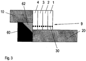
- Fig. 3 shows a schematic sectional view of a lap joint weld joint according to an embodiment.
- Two overlapping arranged components 10, 20, an analogous structure, to the components in Fig. 1 and Fig. 2 are welded together by four friction stir welds 1, 2, 3, 4.
- the overlapping area 30 has been removed to the weld 1 by means of a machining operation in order to produce a gap-free connection.
- an auxiliary tool 60 is shown, which has a recess 62 at the top right. The auxiliary tool is arranged so that the component 10 is clamped between the auxiliary tool 60 and the welding tool 50 and both components 10, 20 rest against the auxiliary tool 60. Material of both components 10, 20 is in a recess 62 on the auxiliary tool 60, which is adjacent to both components 16, 26, pressed.
- a gap-free welded joint 1 is also produced according to this embodiment.
- the component material is pressed into the recess 62, that it is integrally formed on the first and second components 10, 20 and thereby closes the overlapping area 30 between the two components 10, 20.
Landscapes
- Engineering & Computer Science (AREA)
- Mechanical Engineering (AREA)
- Physics & Mathematics (AREA)
- Optics & Photonics (AREA)
- Pressure Welding/Diffusion-Bonding (AREA)
- Arc Welding In General (AREA)
- Butt Welding And Welding Of Specific Article (AREA)
Claims (9)
- Procédé de fabrication de joints de soudure à recouvrement comprenant les étapes de procédé suivantes :(a) fournir deux composants à relier (10, 20) et qui présentent chacun au moins un socle (16, 26) ;(b) disposer les composants (10, 20) de telle sorte que les socles (16, 26) sont en regard les uns des autres et que les composants (10, 20) se chevauchent dans une zone de recouvrement (30) qui s'étend au moins en partie sur les deux socles (16, 26) ;(c) relier les composants (10, 20) par soudage dans la zone de recouvrement (30) en formant au moins un cordon de soudure (1), dans lequel les zones non soudées (32, 34) en bordure de la zone de recouvrement (30) sont formées le long du cordon de soudure (1), dans lequel pendant l'étape consistant à relier les composants (10, 20), un soudage par friction et malaxage est utilisé comme procédé de soudage, dans lequel un outil à souder rotatif (50) est pressé contre au moins un des composants (10, 20) pour générer une chaleur de frottement, caractérisé par l'étape consistant à :(d) enlever les zones non soudées (32, 34) pour former des surfaces découpées extérieures (7, 9) sur les composants (10, 20) et qui sont disposées avec des angles obtus (α, β) par rapport à la zone de recouvrement (30).
- Procédé selon la revendication 1,
caractérisé en ce
que l'étape consistant à enlever les zones non soudées (32, 34) dans l'étape de procédé (d) se fait par un procédé de traitement par usinage, en particulier par un traitement par fraisage. - Procédé selon la revendication 1 ou la revendication 2,
caractérisé en ce
que, pendant l'étape consistant à relier les composants (10, 20), au moins deux cordons de soudure (1, 2) s'étendant sensiblement parallèlement sont formés et son adjacents les uns aux autres sans espace intermédiaire ou se chevauchent les uns sur les autres. - Procédé selon une des revendications précédentes,
caractérisé en ce
que le socle (16) sur le premier composant (10) est disposé en bordure du premier composant (10) et la première surface découpée extérieure (7) est formée de telle sorte qu'elle s'étend depuis le socle (16) au-dessus d'une face frontale (22) du composant opposé (20) et/ou le socle (26) sur le second composant (20) est disposé en bordure du second composant (20) et la seconde surface découpée extérieure (9) est formée de telle sorte qu'elle s'étend depuis le socle (26) au-dessus d'une face frontale (12) du composant opposé (10). - Joint de soudure à recouvrement comprenant au moins deux composants se chevauchant dans une zone de recouvrement (30) et qui présentent chacun au moins un socle (16, 26) avant le soudage des composants (10, 20), les socles (16, 26) étant orientés l'un par rapport à l'autre avant le soudage des composants (10, 20) et s'étendant au moins en partie dans la zone de recouvrement (30) et au moins un cordon de soudure par friction et malaxage (1) est prévu dans la zone de recouvrement (30) pour relier les deux composants (10, 20) l'un à l'autre,
caractérisé en ce
que des deux côtés du cordon de soudure (1) des surfaces découpées extérieures (7, 9) sont formées latéralement en enlevant le matériau de structure de soudage et sont disposées le long du cordon de soudure (1) avec des angles obtus (a, β) par rapport à la zone de recouvrement (30) des deux composants (10, 20) de telle sorte que l'au moins un cordon de soudure (10) ne présente pas d'interstices dans la zone de recouvrement (30). - Joint de soudure à recouvrement selon une des revendications 5 ou 6,
caractérisé en ce
qu'au moins deux cordons de soudure (1, 2) s'étendant sensiblement parallèlement sont prévus. - Joint de soudure à recouvrement selon la revendication 6,
caractérisé en ce
que les cordons de soudure (1, 2) sont adjacents les uns aux autres. - Joint de soudure à recouvrement selon une des revendications 5 à 7,
caractérisé en ce
que les surfaces découpées extérieures (7, 9) sont uniquement prévues au niveau du socle (16, 26). - Joint de soudure à recouvrement selon une des revendications 5 à 8,
caractérisé en ce
que le socle (16) sur le premier composant (10) est disposé en bordure du premier composant (10) et la première surface découpée extérieure (7) est formée de telle sorte qu'elle s'étend depuis le socle (16) au-dessus d'une face frontale (22) du composant opposé (20) et/ou le socle (26) sur le second composant (20) est disposé en bordure du second composant (20) et la seconde surface découpée extérieure (9) est formée de telle sorte qu'elle s'étend depuis le socle (26) au-dessus d'une face frontale (12) du composant opposé (10).
Priority Applications (1)
| Application Number | Priority Date | Filing Date | Title |
|---|---|---|---|
| EP16185338.7A EP3124162B1 (fr) | 2008-11-26 | 2009-11-19 | Procédé de fabrication d'un joint de soudure par recouvrement et joint de soudure par recouvrement |
Applications Claiming Priority (3)
| Application Number | Priority Date | Filing Date | Title |
|---|---|---|---|
| US11825508P | 2008-11-26 | 2008-11-26 | |
| DE102008044087A DE102008044087A1 (de) | 2008-11-26 | 2008-11-26 | Verfahren zum Herstellen von Überlappungsstoßschweißverbindungen und Überlappungsstoßschweißverbindung |
| PCT/EP2009/065505 WO2010060860A2 (fr) | 2008-11-26 | 2009-11-19 | Procédé de réalisation de joints soudés à recouvrement et joint soudé à recouvrement |
Related Child Applications (2)
| Application Number | Title | Priority Date | Filing Date |
|---|---|---|---|
| EP16185338.7A Division EP3124162B1 (fr) | 2008-11-26 | 2009-11-19 | Procédé de fabrication d'un joint de soudure par recouvrement et joint de soudure par recouvrement |
| EP16185338.7A Division-Into EP3124162B1 (fr) | 2008-11-26 | 2009-11-19 | Procédé de fabrication d'un joint de soudure par recouvrement et joint de soudure par recouvrement |
Publications (2)
| Publication Number | Publication Date |
|---|---|
| EP2384255A2 EP2384255A2 (fr) | 2011-11-09 |
| EP2384255B1 true EP2384255B1 (fr) | 2018-04-04 |
Family
ID=42114351
Family Applications (2)
| Application Number | Title | Priority Date | Filing Date |
|---|---|---|---|
| EP09759933.6A Not-in-force EP2384255B1 (fr) | 2008-11-26 | 2009-11-19 | Procédé dôbtention d'un joint de soudure à recouvrement et joint obtenu |
| EP16185338.7A Active EP3124162B1 (fr) | 2008-11-26 | 2009-11-19 | Procédé de fabrication d'un joint de soudure par recouvrement et joint de soudure par recouvrement |
Family Applications After (1)
| Application Number | Title | Priority Date | Filing Date |
|---|---|---|---|
| EP16185338.7A Active EP3124162B1 (fr) | 2008-11-26 | 2009-11-19 | Procédé de fabrication d'un joint de soudure par recouvrement et joint de soudure par recouvrement |
Country Status (9)
| Country | Link |
|---|---|
| US (1) | US8770464B2 (fr) |
| EP (2) | EP2384255B1 (fr) |
| JP (1) | JP2012509772A (fr) |
| CN (1) | CN102227285B (fr) |
| BR (1) | BRPI0921227A2 (fr) |
| CA (1) | CA2747984A1 (fr) |
| DE (1) | DE102008044087A1 (fr) |
| RU (1) | RU2497642C2 (fr) |
| WO (1) | WO2010060860A2 (fr) |
Families Citing this family (7)
| Publication number | Priority date | Publication date | Assignee | Title |
|---|---|---|---|---|
| JP5144856B2 (ja) * | 2009-09-17 | 2013-02-13 | 豊田鉄工株式会社 | 操作ペダル、および重ね合わせ溶接方法 |
| DE102010017269B3 (de) * | 2010-06-08 | 2011-12-08 | Andreas Martin Hofer | Wärmekollektormodul zur deckseitigen Montage auf einer Dachplatte |
| FR2995237B1 (fr) | 2012-09-07 | 2015-05-01 | Airbus Operations Sas | Systeme ameliore de soudage par friction malaxage comprenant un contre-appui mobile. |
| FR2995236B1 (fr) | 2012-09-07 | 2015-05-01 | Airbus Operations Sas | Procede et systeme ameliores de soudage par friction malaxage d'un raidisseur sur un panneau d'aeronef. |
| JP6216764B2 (ja) * | 2015-12-24 | 2017-10-18 | 本田技研工業株式会社 | 異種金属接合方法及び異種金属接合部材 |
| WO2020075802A1 (fr) * | 2018-10-12 | 2020-04-16 | Dic株式会社 | Composite métal/résine et son procédé de production |
| FR3089442B1 (fr) * | 2018-12-05 | 2020-12-18 | Airbus Operations Sas | Procédé d’assemblage d’au moins deux pièces par soudage par transparence, procédé d’assemblage d’une structure primaire d’un mât d’aéronef par soudage par transparence, structure primaire d’un mât d’aéronef ainsi obtenue et aéronef comprenant ladite structure primaire |
Family Cites Families (12)
| Publication number | Priority date | Publication date | Assignee | Title |
|---|---|---|---|---|
| SU837679A1 (ru) * | 1979-09-05 | 1981-06-15 | Предприятие П/Я М-5671 | Способ сварки деталей |
| SU941086A1 (ru) * | 1980-10-20 | 1982-07-07 | Всесоюзный научно-исследовательский, проектно-конструкторский и технологический институт электросварочного оборудования | Способ контактной рельефной сварки |
| JP3070735B2 (ja) | 1997-07-23 | 2000-07-31 | 株式会社日立製作所 | 摩擦攪拌接合方法 |
| JPH1158039A (ja) * | 1997-08-18 | 1999-03-02 | Showa Alum Corp | 摩擦撹拌接合による重ね継手及びその形成方法 |
| JP3553012B2 (ja) * | 2000-11-17 | 2004-08-11 | 株式会社日立製作所 | 摩擦攪拌接合方法 |
| US6676008B1 (en) * | 2002-04-30 | 2004-01-13 | Edison Welding Institute | Friction stir welding of corner configurations |
| JP2004042049A (ja) * | 2002-07-08 | 2004-02-12 | Sumitomo Light Metal Ind Ltd | 流体圧成形管の製造方法 |
| DE10336668A1 (de) | 2003-08-09 | 2005-02-24 | Daimlerchrysler Ag | Fügestellenstruktur für ein Reibschweißverfahren und Verfahren zu deren Herstellung |
| US7455211B2 (en) * | 2003-12-29 | 2008-11-25 | The Boeing Company | Multi-pass friction stir welding |
| KR100780019B1 (ko) * | 2005-02-01 | 2007-11-27 | 가부시끼가이샤 히다치 세이사꾸쇼 | 마찰교반접합방법 |
| US7732033B2 (en) * | 2005-08-26 | 2010-06-08 | The Curators Of The University Of Missouri | Sealants for structural member joints and methods of using same |
| JP2007301573A (ja) * | 2006-05-08 | 2007-11-22 | Honda Motor Co Ltd | 摩擦攪拌接合方法および摩擦攪拌接合構造体 |
-
2008
- 2008-11-26 DE DE102008044087A patent/DE102008044087A1/de not_active Withdrawn
-
2009
- 2009-11-19 EP EP09759933.6A patent/EP2384255B1/fr not_active Not-in-force
- 2009-11-19 BR BRPI0921227A patent/BRPI0921227A2/pt not_active Application Discontinuation
- 2009-11-19 CA CA2747984A patent/CA2747984A1/fr not_active Abandoned
- 2009-11-19 JP JP2011537942A patent/JP2012509772A/ja active Pending
- 2009-11-19 EP EP16185338.7A patent/EP3124162B1/fr active Active
- 2009-11-19 RU RU2011123696/02A patent/RU2497642C2/ru not_active IP Right Cessation
- 2009-11-19 WO PCT/EP2009/065505 patent/WO2010060860A2/fr not_active Ceased
- 2009-11-19 CN CN200980147496.2A patent/CN102227285B/zh not_active Expired - Fee Related
-
2011
- 2011-05-05 US US13/101,230 patent/US8770464B2/en active Active
Also Published As
| Publication number | Publication date |
|---|---|
| EP3124162B1 (fr) | 2020-04-29 |
| JP2012509772A (ja) | 2012-04-26 |
| WO2010060860A2 (fr) | 2010-06-03 |
| CN102227285B (zh) | 2014-03-12 |
| BRPI0921227A2 (pt) | 2016-02-23 |
| RU2011123696A (ru) | 2013-01-10 |
| CA2747984A1 (fr) | 2010-06-03 |
| WO2010060860A4 (fr) | 2010-11-25 |
| US20110268494A1 (en) | 2011-11-03 |
| US8770464B2 (en) | 2014-07-08 |
| CN102227285A (zh) | 2011-10-26 |
| WO2010060860A3 (fr) | 2010-09-23 |
| EP2384255A2 (fr) | 2011-11-09 |
| EP3124162A1 (fr) | 2017-02-01 |
| RU2497642C2 (ru) | 2013-11-10 |
| DE102008044087A1 (de) | 2010-05-27 |
Similar Documents
| Publication | Publication Date | Title |
|---|---|---|
| EP3600746B1 (fr) | Procédé servant à fabriquer un composant pour une application de véhicule | |
| DE60310020T2 (de) | Verbinden von strukturkomponenten mittels reibschweissen mit einem verbindungsstift | |
| EP3124162B1 (fr) | Procédé de fabrication d'un joint de soudure par recouvrement et joint de soudure par recouvrement | |
| DE102013000574B4 (de) | Rührreibschweißvorrichtung sowie Verfahren zum Rührreibschweißen | |
| DE102013106692B4 (de) | Rührreibschweissverfahren für metallwerkstück | |
| DE102012200420A1 (de) | Verbindungsverfahren und verbindungswerkzeug | |
| AT525908B1 (de) | Rührschweißvorrichtung zur Herstellung einer Schweißverbindung | |
| WO2017167964A1 (fr) | Procédé de soudage par friction-malaxage, tige et dispositif d'usinage pour l'assemblage de pièces composées de matériaux différents, ainsi que joint soudé afférent | |
| DE102010032402A1 (de) | Verfahren zum Verbinden von zwei Luftfahrzeugrumpfsegmenten mittels Rührreibschweißen | |
| DE60102997T2 (de) | Reibrührschweißverfahren | |
| EP3600756B1 (fr) | Procédé de fabrication d'une pièce composite et pièce composite | |
| DE102006000277B4 (de) | Verfahren zum miteinander erfolgenden Verbinden von Endabschnitten von übereinander angeordneten Elementen | |
| DE10345105B4 (de) | Konusverschluss für Laserschweissnaht an einem Bestandteil einer Luftansaugung | |
| EP1518633B1 (fr) | Procédé de soudage et article assemblé | |
| DE102010049872A1 (de) | Reibschweißverbindung | |
| DE102015001151A1 (de) | Verfahren zum Herstellen einer Schweißverbindung | |
| DE102005037134A1 (de) | Reibschweiß-basiertes Verfahren zum Verbinden zweier flächiger Fügepartner | |
| WO2019038334A1 (fr) | Procédé de soudage pour un composite multicouche comprenant une couche barrière | |
| DE10131883B4 (de) | Verfahren zum Verschweißen von Metallbauteilen | |
| DE102016119062A1 (de) | Rührreibschweißtechnologie zum Verbinden von Bauteilen aus unterschiedlichen Materialien | |
| DE102004008108B4 (de) | Überlappstoß zum Schweißen von beschichteten Werkstücken | |
| DE69601293T2 (de) | Verfahren zum Regeln von Schweissparametern zum Schweissen von zwei metallischen Werkstücken | |
| EP3569341B1 (fr) | Assemblage de pièces avec un matériau thermiquement expansible | |
| DE102015002427A1 (de) | Verfahren zum Herstellen einer Fügeverbindung und Fügeverbindung | |
| WO2020126197A1 (fr) | Procédé pour assembler deux éléments structuraux, notamment pour un véhicule automobile, ainsi qu'unité modulaire |
Legal Events
| Date | Code | Title | Description |
|---|---|---|---|
| PUAI | Public reference made under article 153(3) epc to a published international application that has entered the european phase |
Free format text: ORIGINAL CODE: 0009012 |
|
| 17P | Request for examination filed |
Effective date: 20110622 |
|
| AK | Designated contracting states |
Kind code of ref document: A2 Designated state(s): AT BE BG CH CY CZ DE DK EE ES FI FR GB GR HR HU IE IS IT LI LT LU LV MC MK MT NL NO PL PT RO SE SI SK SM TR |
|
| DAX | Request for extension of the european patent (deleted) | ||
| 17Q | First examination report despatched |
Effective date: 20151111 |
|
| STAA | Information on the status of an ep patent application or granted ep patent |
Free format text: STATUS: EXAMINATION IS IN PROGRESS |
|
| GRAP | Despatch of communication of intention to grant a patent |
Free format text: ORIGINAL CODE: EPIDOSNIGR1 |
|
| STAA | Information on the status of an ep patent application or granted ep patent |
Free format text: STATUS: GRANT OF PATENT IS INTENDED |
|
| INTG | Intention to grant announced |
Effective date: 20171206 |
|
| GRAS | Grant fee paid |
Free format text: ORIGINAL CODE: EPIDOSNIGR3 |
|
| GRAA | (expected) grant |
Free format text: ORIGINAL CODE: 0009210 |
|
| STAA | Information on the status of an ep patent application or granted ep patent |
Free format text: STATUS: THE PATENT HAS BEEN GRANTED |
|
| AK | Designated contracting states |
Kind code of ref document: B1 Designated state(s): AT BE BG CH CY CZ DE DK EE ES FI FR GB GR HR HU IE IS IT LI LT LU LV MC MK MT NL NO PL PT RO SE SI SK SM TR |
|
| REG | Reference to a national code |
Ref country code: GB Ref legal event code: FG4D Free format text: NOT ENGLISH |
|
| REG | Reference to a national code |
Ref country code: CH Ref legal event code: EP |
|
| REG | Reference to a national code |
Ref country code: AT Ref legal event code: REF Ref document number: 985071 Country of ref document: AT Kind code of ref document: T Effective date: 20180415 |
|
| REG | Reference to a national code |
Ref country code: IE Ref legal event code: FG4D Free format text: LANGUAGE OF EP DOCUMENT: GERMAN |
|
| REG | Reference to a national code |
Ref country code: DE Ref legal event code: R096 Ref document number: 502009014870 Country of ref document: DE |
|
| REG | Reference to a national code |
Ref country code: NL Ref legal event code: MP Effective date: 20180404 |
|
| REG | Reference to a national code |
Ref country code: LT Ref legal event code: MG4D |
|
| PG25 | Lapsed in a contracting state [announced via postgrant information from national office to epo] |
Ref country code: NL Free format text: LAPSE BECAUSE OF FAILURE TO SUBMIT A TRANSLATION OF THE DESCRIPTION OR TO PAY THE FEE WITHIN THE PRESCRIBED TIME-LIMIT Effective date: 20180404 |
|
| PG25 | Lapsed in a contracting state [announced via postgrant information from national office to epo] |
Ref country code: NO Free format text: LAPSE BECAUSE OF FAILURE TO SUBMIT A TRANSLATION OF THE DESCRIPTION OR TO PAY THE FEE WITHIN THE PRESCRIBED TIME-LIMIT Effective date: 20180704 Ref country code: BG Free format text: LAPSE BECAUSE OF FAILURE TO SUBMIT A TRANSLATION OF THE DESCRIPTION OR TO PAY THE FEE WITHIN THE PRESCRIBED TIME-LIMIT Effective date: 20180704 Ref country code: FI Free format text: LAPSE BECAUSE OF FAILURE TO SUBMIT A TRANSLATION OF THE DESCRIPTION OR TO PAY THE FEE WITHIN THE PRESCRIBED TIME-LIMIT Effective date: 20180404 Ref country code: SE Free format text: LAPSE BECAUSE OF FAILURE TO SUBMIT A TRANSLATION OF THE DESCRIPTION OR TO PAY THE FEE WITHIN THE PRESCRIBED TIME-LIMIT Effective date: 20180404 Ref country code: ES Free format text: LAPSE BECAUSE OF FAILURE TO SUBMIT A TRANSLATION OF THE DESCRIPTION OR TO PAY THE FEE WITHIN THE PRESCRIBED TIME-LIMIT Effective date: 20180404 Ref country code: LT Free format text: LAPSE BECAUSE OF FAILURE TO SUBMIT A TRANSLATION OF THE DESCRIPTION OR TO PAY THE FEE WITHIN THE PRESCRIBED TIME-LIMIT Effective date: 20180404 Ref country code: PL Free format text: LAPSE BECAUSE OF FAILURE TO SUBMIT A TRANSLATION OF THE DESCRIPTION OR TO PAY THE FEE WITHIN THE PRESCRIBED TIME-LIMIT Effective date: 20180404 |
|
| PG25 | Lapsed in a contracting state [announced via postgrant information from national office to epo] |
Ref country code: LV Free format text: LAPSE BECAUSE OF FAILURE TO SUBMIT A TRANSLATION OF THE DESCRIPTION OR TO PAY THE FEE WITHIN THE PRESCRIBED TIME-LIMIT Effective date: 20180404 Ref country code: HR Free format text: LAPSE BECAUSE OF FAILURE TO SUBMIT A TRANSLATION OF THE DESCRIPTION OR TO PAY THE FEE WITHIN THE PRESCRIBED TIME-LIMIT Effective date: 20180404 Ref country code: GR Free format text: LAPSE BECAUSE OF FAILURE TO SUBMIT A TRANSLATION OF THE DESCRIPTION OR TO PAY THE FEE WITHIN THE PRESCRIBED TIME-LIMIT Effective date: 20180705 |
|
| PG25 | Lapsed in a contracting state [announced via postgrant information from national office to epo] |
Ref country code: PT Free format text: LAPSE BECAUSE OF FAILURE TO SUBMIT A TRANSLATION OF THE DESCRIPTION OR TO PAY THE FEE WITHIN THE PRESCRIBED TIME-LIMIT Effective date: 20180806 |
|
| REG | Reference to a national code |
Ref country code: DE Ref legal event code: R097 Ref document number: 502009014870 Country of ref document: DE |
|
| PG25 | Lapsed in a contracting state [announced via postgrant information from national office to epo] |
Ref country code: EE Free format text: LAPSE BECAUSE OF FAILURE TO SUBMIT A TRANSLATION OF THE DESCRIPTION OR TO PAY THE FEE WITHIN THE PRESCRIBED TIME-LIMIT Effective date: 20180404 Ref country code: RO Free format text: LAPSE BECAUSE OF FAILURE TO SUBMIT A TRANSLATION OF THE DESCRIPTION OR TO PAY THE FEE WITHIN THE PRESCRIBED TIME-LIMIT Effective date: 20180404 Ref country code: CZ Free format text: LAPSE BECAUSE OF FAILURE TO SUBMIT A TRANSLATION OF THE DESCRIPTION OR TO PAY THE FEE WITHIN THE PRESCRIBED TIME-LIMIT Effective date: 20180404 Ref country code: SK Free format text: LAPSE BECAUSE OF FAILURE TO SUBMIT A TRANSLATION OF THE DESCRIPTION OR TO PAY THE FEE WITHIN THE PRESCRIBED TIME-LIMIT Effective date: 20180404 Ref country code: DK Free format text: LAPSE BECAUSE OF FAILURE TO SUBMIT A TRANSLATION OF THE DESCRIPTION OR TO PAY THE FEE WITHIN THE PRESCRIBED TIME-LIMIT Effective date: 20180404 |
|
| PLBE | No opposition filed within time limit |
Free format text: ORIGINAL CODE: 0009261 |
|
| STAA | Information on the status of an ep patent application or granted ep patent |
Free format text: STATUS: NO OPPOSITION FILED WITHIN TIME LIMIT |
|
| PG25 | Lapsed in a contracting state [announced via postgrant information from national office to epo] |
Ref country code: SM Free format text: LAPSE BECAUSE OF FAILURE TO SUBMIT A TRANSLATION OF THE DESCRIPTION OR TO PAY THE FEE WITHIN THE PRESCRIBED TIME-LIMIT Effective date: 20180404 Ref country code: IT Free format text: LAPSE BECAUSE OF FAILURE TO SUBMIT A TRANSLATION OF THE DESCRIPTION OR TO PAY THE FEE WITHIN THE PRESCRIBED TIME-LIMIT Effective date: 20180404 |
|
| 26N | No opposition filed |
Effective date: 20190107 |
|
| PG25 | Lapsed in a contracting state [announced via postgrant information from national office to epo] |
Ref country code: SI Free format text: LAPSE BECAUSE OF FAILURE TO SUBMIT A TRANSLATION OF THE DESCRIPTION OR TO PAY THE FEE WITHIN THE PRESCRIBED TIME-LIMIT Effective date: 20180404 |
|
| REG | Reference to a national code |
Ref country code: CH Ref legal event code: PL |
|
| PG25 | Lapsed in a contracting state [announced via postgrant information from national office to epo] |
Ref country code: LU Free format text: LAPSE BECAUSE OF NON-PAYMENT OF DUE FEES Effective date: 20181119 Ref country code: MC Free format text: LAPSE BECAUSE OF FAILURE TO SUBMIT A TRANSLATION OF THE DESCRIPTION OR TO PAY THE FEE WITHIN THE PRESCRIBED TIME-LIMIT Effective date: 20180404 |
|
| REG | Reference to a national code |
Ref country code: BE Ref legal event code: MM Effective date: 20181130 |
|
| REG | Reference to a national code |
Ref country code: IE Ref legal event code: MM4A |
|
| PG25 | Lapsed in a contracting state [announced via postgrant information from national office to epo] |
Ref country code: LI Free format text: LAPSE BECAUSE OF NON-PAYMENT OF DUE FEES Effective date: 20181130 Ref country code: CH Free format text: LAPSE BECAUSE OF NON-PAYMENT OF DUE FEES Effective date: 20181130 |
|
| PG25 | Lapsed in a contracting state [announced via postgrant information from national office to epo] |
Ref country code: IE Free format text: LAPSE BECAUSE OF NON-PAYMENT OF DUE FEES Effective date: 20181119 |
|
| PG25 | Lapsed in a contracting state [announced via postgrant information from national office to epo] |
Ref country code: BE Free format text: LAPSE BECAUSE OF NON-PAYMENT OF DUE FEES Effective date: 20181130 |
|
| REG | Reference to a national code |
Ref country code: AT Ref legal event code: MM01 Ref document number: 985071 Country of ref document: AT Kind code of ref document: T Effective date: 20181119 |
|
| PG25 | Lapsed in a contracting state [announced via postgrant information from national office to epo] |
Ref country code: AT Free format text: LAPSE BECAUSE OF NON-PAYMENT OF DUE FEES Effective date: 20181119 Ref country code: MT Free format text: LAPSE BECAUSE OF FAILURE TO SUBMIT A TRANSLATION OF THE DESCRIPTION OR TO PAY THE FEE WITHIN THE PRESCRIBED TIME-LIMIT Effective date: 20180404 |
|
| PGFP | Annual fee paid to national office [announced via postgrant information from national office to epo] |
Ref country code: DE Payment date: 20191121 Year of fee payment: 11 |
|
| PGFP | Annual fee paid to national office [announced via postgrant information from national office to epo] |
Ref country code: FR Payment date: 20191120 Year of fee payment: 11 |
|
| PG25 | Lapsed in a contracting state [announced via postgrant information from national office to epo] |
Ref country code: TR Free format text: LAPSE BECAUSE OF FAILURE TO SUBMIT A TRANSLATION OF THE DESCRIPTION OR TO PAY THE FEE WITHIN THE PRESCRIBED TIME-LIMIT Effective date: 20180404 |
|
| PGFP | Annual fee paid to national office [announced via postgrant information from national office to epo] |
Ref country code: GB Payment date: 20191120 Year of fee payment: 11 |
|
| PG25 | Lapsed in a contracting state [announced via postgrant information from national office to epo] |
Ref country code: HU Free format text: LAPSE BECAUSE OF FAILURE TO SUBMIT A TRANSLATION OF THE DESCRIPTION OR TO PAY THE FEE WITHIN THE PRESCRIBED TIME-LIMIT; INVALID AB INITIO Effective date: 20091119 Ref country code: CY Free format text: LAPSE BECAUSE OF FAILURE TO SUBMIT A TRANSLATION OF THE DESCRIPTION OR TO PAY THE FEE WITHIN THE PRESCRIBED TIME-LIMIT Effective date: 20180404 Ref country code: MK Free format text: LAPSE BECAUSE OF NON-PAYMENT OF DUE FEES Effective date: 20180404 |
|
| PG25 | Lapsed in a contracting state [announced via postgrant information from national office to epo] |
Ref country code: IS Free format text: LAPSE BECAUSE OF FAILURE TO SUBMIT A TRANSLATION OF THE DESCRIPTION OR TO PAY THE FEE WITHIN THE PRESCRIBED TIME-LIMIT Effective date: 20180804 |
|
| REG | Reference to a national code |
Ref country code: DE Ref legal event code: R119 Ref document number: 502009014870 Country of ref document: DE |
|
| GBPC | Gb: european patent ceased through non-payment of renewal fee |
Effective date: 20201119 |
|
| PG25 | Lapsed in a contracting state [announced via postgrant information from national office to epo] |
Ref country code: FR Free format text: LAPSE BECAUSE OF NON-PAYMENT OF DUE FEES Effective date: 20201130 |
|
| PG25 | Lapsed in a contracting state [announced via postgrant information from national office to epo] |
Ref country code: GB Free format text: LAPSE BECAUSE OF NON-PAYMENT OF DUE FEES Effective date: 20201119 Ref country code: DE Free format text: LAPSE BECAUSE OF NON-PAYMENT OF DUE FEES Effective date: 20210601 |