EP2384676B1 - Mit einer Sicherheitsvorrichtung verschließbares Elektro-Haushaltsgerät zur Essenszubereitung - Google Patents
Mit einer Sicherheitsvorrichtung verschließbares Elektro-Haushaltsgerät zur Essenszubereitung Download PDFInfo
- Publication number
- EP2384676B1 EP2384676B1 EP20110305539 EP11305539A EP2384676B1 EP 2384676 B1 EP2384676 B1 EP 2384676B1 EP 20110305539 EP20110305539 EP 20110305539 EP 11305539 A EP11305539 A EP 11305539A EP 2384676 B1 EP2384676 B1 EP 2384676B1
- Authority
- EP
- European Patent Office
- Prior art keywords
- cup
- motorised
- box
- household electrical
- food preparation
- Prior art date
- Legal status (The legal status is an assumption and is not a legal conclusion. Google has not performed a legal analysis and makes no representation as to the accuracy of the status listed.)
- Not-in-force
Links
- 238000001514 detection method Methods 0.000 claims description 24
- 230000000903 blocking effect Effects 0.000 claims description 4
- 238000007373 indentation Methods 0.000 description 5
- 238000010276 construction Methods 0.000 description 3
- 230000002093 peripheral effect Effects 0.000 description 2
- 238000010411 cooking Methods 0.000 description 1
- 238000006073 displacement reaction Methods 0.000 description 1
- 238000012986 modification Methods 0.000 description 1
- 230000004048 modification Effects 0.000 description 1
Images



Classifications
-
- A—HUMAN NECESSITIES
- A47—FURNITURE; DOMESTIC ARTICLES OR APPLIANCES; COFFEE MILLS; SPICE MILLS; SUCTION CLEANERS IN GENERAL
- A47J—KITCHEN EQUIPMENT; COFFEE MILLS; SPICE MILLS; APPARATUS FOR MAKING BEVERAGES
- A47J43/00—Implements for preparing or holding food, not provided for in other groups of this subclass
- A47J43/04—Machines for domestic use not covered elsewhere, e.g. for grinding, mixing, stirring, kneading, emulsifying, whipping or beating foodstuffs, e.g. power-driven
- A47J43/07—Parts or details, e.g. mixing tools, whipping tools
- A47J43/075—Safety devices
- A47J43/0755—Safety devices for machines with tools driven from the upper side
Definitions
- the present invention relates to the technical field of electrical household appliances for culinary preparation comprising a rotary working tool arranged in a working container and an upper motorized housing mounted on the working container.
- the present invention more particularly relates to apparatus of the aforementioned type in which the upper motorized housing is locked on the working container and comprises a safety device provided for detecting the presence of the working container and a cup interposed between the upper motor housing and the working container.
- the document WO 98/24350 discloses an apparatus comprising a motorized upper case locked on a cup by means of a moving part moved by a control button, the cup having a shutter wall locked by bayonet on the working container by means of another moving part .
- An object of the present invention is to provide a food preparation apparatus comprising a motorized upper case locked on a working container and a safety device, which has a simplified construction.
- Another object of the present invention is to provide a food preparation apparatus comprising a motorized upper case locked on a working container and a safety device, which has a facilitated use.
- a household appliance preparation a motorized upper motor housing arranged on a working receptacle housing a cup, the upper motorized housing carrying a movable safety element between a rest position which does not allow the operation of the apparatus and an active position allowing the operation of the the apparatus, since the cup in place under the upper motor housing pushes the safety element to an intermediate position which does not allow the operation of the apparatus, that the upper motor housing is rotatably locked to the container of the workpiece carrying the cup, and that the working container has a cam surface adapted to push the safety element from the intermediate position to the active position during locking by rotation of the upper motor housing on the working container carrying the cup.
- the security element directly detects the presence of the working container and the cup.
- the movement of the safety element from the rest position to the active position comprises a first part made by the cup, making it possible to reach an intermediate position of the safety element, and a second part made by the working container. , from the intermediate position of the security element.
- the cam surface of the working container allows different directions to be used for the positioning movement of the cup and for the locking movement of the working container with the upper motor housing.
- the device has both a simple and safe use.
- the upper motorized housing is bayonet-locked on the working container. This arrangement makes it possible to limit the rotation of the upper motor housing relative to the working receptacle in order to lock the apparatus.
- the upper motorized housing could in particular be screwed on the working container.
- the working receptacle comprises locking members extending inside said working receptacle. This arrangement reduces the size of the device, the lower part of the upper motorized housing can be inserted into the working container.
- the security element comprises a detection member mounted in an opening of a lower wall of the upper motor housing and the cup in place under the upper motorized housing pushes the detection member towards the inside of the upper motor housing.
- the upper motorized housing can simply be placed on the cup in place in the working container, to bring the security element to the intermediate position.
- the detection member is prominent inside a cavity of said bottom wall when the security element occupies the rest position. This arrangement makes it more difficult for the user to actuate the detection member.
- the cup has an upper face having an annular detection zone arranged opposite the detection member, said annular detection zone having a geometry of revolution.
- This arrangement allows to set up the cup in the working container, without particular orientation. The use of the apparatus is thus facilitated.
- the annular detection zone is formed by an annular upper rib of the cup. This arrangement reduces the size of the security element.
- the cam surface is formed by a beveled control member having a lower surface adapted to cooperate with a bearing surface of the upper motor housing and an upper surface provided to push the safety element towards the active position when rotating the working container relative to the upper motor housing to lock the upper motor housing on the working container carrying the cup.
- the lower surface of the control member thus makes it possible to lock the upper motorized housing on the working receptacle, the upper surface of the control member moving the safety element towards the active operating position of the apparatus.
- the surface lower and / or the upper surface may be inclined relative to the plane of rotation of the upper motor housing on the working container.
- the security element has a blocking member hindering the stroke of the control member when locking the upper motor housing on the working container in the absence of the cup.
- This arrangement avoids locking the upper motor housing on the working container in the absence of the cup. The user trying to lock the device to make it work is thus informed that the device is not used in a compliant configuration.
- the security element could have a locking member hindering the stroke of another part of the working container.
- the working container has an internal annular support zone intended to receive the cup. This arrangement ensures a relative seal between the working container and the cup at said annular support zone.
- the upper motorized housing comprises a switch controlling the operation of the apparatus and a movable control button between a stop position in which the switch does not allow the operation of the apparatus and a position in operation. which switch allows operation of the apparatus when the security element is in the active position.
- the switch is mounted on a mobile support that can be moved by the control button between a raised position in which the switch does not allow the operation of the device and a lowered position in which the switch allows operation of the device when the security element is in the active position.
- the appliance for cooking preparation illustrated on the Figures 1 to 13 has a motorized upper case 1, a cup 2, a working tool rotating 3 and a working container 4.
- the upper motor housing 1 is disposed on the working container 4.
- the working container 4 carries the upper motor housing 1.
- the upper motorized housing 1 houses a motor 10 (visible on the figure 5 ) for driving the rotary working tool 3 arranged in the working receptacle 4.
- the motor 10 is connected to a driving member 11 arranged on the lower side of the upper motor housing 1.
- the upper motor housing 1 is locked by rotation on the working receptacle 4 carrying the cup 2.
- the working receptacle 4 comprises locking members 40 provided to cooperate with retaining members 12 belonging to the upper motor housing 1.
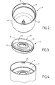
- the upper motorized housing 1 is bayonet-locked on the working receptacle 4. As visible on the figure 2 the working receptacle 4 has three locking members 40; the upper motorized housing 1 comprises three retaining members 12 provided for retaining the locking members 40.
- the upper motorized housing 1 has a lower portion 13 adapted to be inserted into the working receptacle 4.
- the locking members 40 extend inside the working receptacle 4.
- the retaining members 12 are arranged in the outside of the lower portion 13 of the upper motor housing 1.
- the lower portion 13 has three inverted lateral cutouts L 14 housing the retaining members 12, the lateral indentations 14 being provided to receive the locking members 40 .
- the working container 4 houses the cup 2.
- the working receptacle 4 has an internal annular support zone 41 designed to receive the cup 2.
- the cup 2 is arranged in the working container 4.
- the cup 2 rests on the internal annular support zone 41.
- cup 2 has a peripheral edge 20 provided to rest on the inner annular support zone 41.
- the peripheral edge 20 is arranged on an annular upper rib 21 of the cup 2.
- the cup 2 has a central opening 22 provided for the passage of the part upper part of the rotary working tool 3.
- the working container 4 houses the rotary working tool 3.
- the upper motorized housing 1 comprises a main body 15, mounted on the lower part 13, the main body 15 being visible on the figure 1 but not being represented on the figure 5 .
- the upper motor housing 1 comprises a switch 50 controlling the operation of the apparatus.
- the upper motorized box 1 comprises a control button 51, visible on the figure 5 .
- the control button 51 is carried by the main body 15.
- the control button 51 is mounted to move against an elastic return member 52.
- the resilient return member 52 rests for example on the motor 10.
- the control button 51 is capable of displacing a movable support 53 carrying the switch 50.
- the movable support 53 is movably mounted against resilient return means 54.
- the elastic return means 54 rest for example on the lower part 13.
- the upper motorized housing 1 carries a movable security element 60 between a rest position which does not allow the operation of the apparatus, illustrated in FIG. figure 11 , and an active position allowing the operation of the apparatus, illustrated on the figure 13 .
- the cup 2 in place under the upper motorized housing 1 pushes the security element 60 to an intermediate position that does not allow the operation of the device.
- the intermediate position of the security element 60 is illustrated on the figure 12 .
- the control button 51 is movable between a stop position in which the switch 50 does not allow the operation of the apparatus and an on position in which the switch 50 allows the operation of the apparatus when the security element 60 is in the active position.
- the switch 50 is mounted on the movable support 53 that can be moved by the control button 51 between a position raised in which the switch 50 does not allow the operation of the apparatus and a lowered position in which the switch 50 allows the operation of the apparatus when the security element 60 occupies the active position.
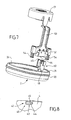
- the security element 60 comprises a detection member 61 designed to cooperate with the cup 2. As visible on the figure 6 , the detection member 61 is mounted in an opening 16 of a lower wall 17 of the upper motorized housing 1. The detection member 61 is prominent inside a cavity 19 of said lower wall 17 when the safety element 60 occupies the rest position. The cup 2 in place under the upper motorized casing 1 pushes the detection member 61 towards the inside of the upper motorized casing 1.
- the cup 2 has an upper face 23 visible on the figure 3 .
- the upper face 23 of the cup 2 comprises an annular detection zone 24 arranged facing the detection member 61, when the cup 2 is in place under the security element 60, as shown in FIG. figure 7 .
- the annular detection zone 24 has a geometry of revolution, allowing placement of the cup 2 under the upper motorized casing 1 without particular angular indexing. More particularly, the annular detection zone 24 is formed by the annular upper rib 21 of the cup 2.
- the cavity 19 is formed by an annular groove.
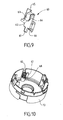
- the working receptacle 4 has a cam surface 42 adapted to push the safety element 60 from the intermediate position to the active position when the motorized upper housing 1 is locked by rotation on the working receptacle 4 carrying the cup 2. that visible on the figure 8 the cam surface 42 is formed by a beveled control member 43 having a lower surface 44 and an upper surface 45.
- the lower surface 44 is provided to cooperate with a bearing surface 18 of the upper motorized housing 1. More particularly, the control member 43 corresponds to one of the locking members 40, and the bearing surface 18 corresponds to the retaining member 12 adjacent to the element security 60.
- the upper surface 45 is provided to push the safety element 60 towards the active position during the rotation of the working receptacle 4 relative to the upper motor housing 1 to lock the upper motor housing 1 on the working receptacle 4 carrying the cup 2.
- the upper surface 45 pushes a second detecting member 62 of the security element 60. More particularly, the second detecting member 62 is formed by the lower end of a tab 63 arranged in one of the lateral indentations. 14 of the lower part 13 of the upper motor housing 1.
- the safety element 60 has a blocking member 64 which prevents the stroke of the control member 43 when the upper motorized housing 1 is locked on the working receptacle 4 in the absence of the cup 2, when the security 60 occupies the rest position. More particularly, the blocking member 64 is formed by a lateral face of the tongue 63 arranged in one of the lateral indentations 14 of the lower part 13 of the upper motorized box 1.Tel visible on the figure 12 , the locking member 64 occupies the bottom of the notch 14 beyond the bearing surface 18.
- the security element 60 has an upper actuating surface 65.
- the actuating surface 65 is provided to actuate an actuating button 55 of the switch 50, as visible on the figure 7 .
- the security element 60 has a guiding member 66 provided for translational movement of the safety element 60 relative to the upper motorized housing 1.
- the security element 60 is movably mounted against an elastic return device 67 comprising a helical spring held by a screw 68.
- the apparatus according to the invention is used and operates in the following manner.
- the user sets up the cup 2 in the working receptacle 4, then arranges the upper motor housing 1 on the working receptacle 4 in introducing the locking members 40 of the working receptacle 4 into the lateral indentations 14 of the upper motor housing 1.
- the annular upper rib 21 of the cup 2 pushes the detecting member 61 of the safety element 60.
- safety 60 is then moved from the rest position illustrated on the figure 11 at the intermediate position shown on the figure 12 .
- the locking member 40 forming the cam surface 42 can then be inserted under the second detecting member 62 of the security element 60.
- the user can thus turn the upper motorized housing 1 relative to the working receptacle 4.
- the locking members 40 engaged in the lateral indentations 14 bear on the retaining members 12 and lock the upper motor housing 1 on the working receptacle 4.
- the cam surface 42 bearing on the bearing surface 18 of the motorized housing upper 1 raises the second detection member 62 of the security element 60.
- the security element 60 is then moved from the intermediate position illustrated on the figure 12 at the active position shown on the figure 13 .
- the apparatus can then operate if the user presses the control button 51.
- the displacement of the movable support 53 carrying the switch 50 towards the on position brings the operation button 55 of the switch 50 into contact with the surface actuating device 65 of the security element 60 in the active position.
- the proposed apparatus thus presents an easy use and a relatively simple construction.
- the use of the cup 2 to perform the first part of the movement of the security element 60 and the working container 4 to achieve the second part of the movement of the security element 60 makes the apparatus particularly safe.
- the rotary working tool 3 is not necessarily mounted on the bottom of the working container 4, but could in particular be suspended mounted under the upper motorized housing 1.
- control member 43 could be distinct from the locking members 40.
- the upper motorized housing 1 could be devoid of control button 51, the switch 50 being arranged in the upper motor housing 1 in a position corresponding to the aforementioned operating position, the locking of the motorized upper housing 1 on the working container 4 carrying the cup 2 then bringing the actuating surface 65 of the safety element 60 into the active position in contact with the actuating button 55 of the switch 50.
- the upper motorized housing 1 could be locked by screwing on the working receptacle 4.
Landscapes
- Engineering & Computer Science (AREA)
- Mechanical Engineering (AREA)
- Food Science & Technology (AREA)
- Food-Manufacturing Devices (AREA)
- Cookers (AREA)
Claims (12)
- Elektrohaushaltsgerät für die Zubereitung von Speisen, mit einem oben befindlichen Gehäuse mit Motor (1), das auf einem Arbeitsbehälter (4) sitzt, auf dem sich eine Manschette (2) befindet, wobei das oben befindliche Gehäuse mit Motor (1) mit einem Sicherungselement (60) versehen ist, das zwischen einer Ruhestellung, bei der kein Betrieb des Geräts möglich ist, und einer Aktivierungsstellung, bei der der Betrieb des Geräts möglich ist, zu bewegen ist, dadurch gekennzeichnet, dass die Manschette (2), die sich unter dem oberen Gehäuse mit Motor (1) befindet, das Sicherungselement (60) in eine Zwischenstellung verschiebt, bei der kein Betrieb des Geräts möglich ist, dass das obere Gehäuse mit Motor (1) durch eine Drehung auf dem Arbeitsbehälter (4), auf dem die Manschette (2) sitzt, verriegelt wird, und dass der Arbeitsbehälter (4) eine Nockenfläche (42) aufweist, die das Sicherungselement (60) bei der Verriegelung durch Drehung des oberen Gehäuses mit Motor (1) auf dem Arbeitsbehälter (4), auf dem die Manschette (2) sitzt, aus der Zwischenstellung in die Aktivierungsstellung verschieben kann.
- Elektrohaushaltsgerät für die Zubereitung von Speisen nach Anspruch 1, dadurch gekennzeichnet, dass der oben befindliche Motor (1) durch einen Bajonettriegel auf dem Arbeitsbehälter (4) verriegelt wird.
- Elektrohaushaltsgerät für die Zubereitung von Speisen nach einem der Ansprüche 1 oder 2, dadurch gekennzeichnet, dass der Arbeitsbehälter (4) mit Verriegelungskörpern (40) versehen ist, die über den Innenraum des Arbeitsbehälters (4) verteilt sind.
- Elektrohaushaltsgerät für die Zubereitung von Speisen nach einem der Ansprüche 1 bis 3, dadurch gekennzeichnet, dass das Sicherungselement (60) eine Erkennungsvorrichtung (61) aufweist, die in einer Öffnung (16) einer unteren Wand (17) des oberen Gehäuses mit Motor (1) montiert ist, und dass die Manschette (2), die sich unter dem oberen Gehäuse mit Motor (1) befindet, die Erkennungsvorrichtung (61) in den Innenraum des oberen Gehäuses mit Motor (1) verschiebt.
- Elektrohaushaltsgerät für die Zubereitung von Speisen nach Anspruch 4, dadurch gekennzeichnet, dass die Erkennungsvorrichtung (61) aus einer Vertiefung (19) der unteren Wand (17) herausragt, wenn das Sicherungselement (60) sich in der Ruhestellung befindet.
- Elektrohaushaltsgerät für die Zubereitung von Speisen nach einem der Ansprüche 4 oder 5, dadurch gekennzeichnet, dass die Manschette (2) eine obere Wand (23) aufweist, die mit einer ringförmigen Erkennungszone (24) versehen ist, welche gegenüber der Erkennungsvorrichtung (61) angebracht ist, wobei die ringförmige Erkennungszone (24) ein geometrisches Rotationskonzept aufweist.
- Elektrohaushaltsgerät für die Zubereitung von Speisen nach Anspruch 6, dadurch gekennzeichnet, dass die ringförmige Erkennungszone (24) durch eine ringförmige obere Rippe (21) der Manschette (2) geformt wird.
- Elektrohaushaltsgerät für die Zubereitung von Speisen nach einem der Ansprüche 1 bis 7, dadurch gekennzeichnet, dass die Nockenfläche (42) durch ein abgeschrägtes Betätigungsglied (43) geformt wird, das eine Innenfläche (44) aufweist, die dazu gedacht ist, mit der Auflagefläche (18) des oberen Gehäuses mit Motor (1) und einer Oberseite (45), die zum Verschieben des Sicherungselements (60) in die Aktivierungsstellung bei der Drehung des Arbeitsbehälters (4) entgegen dem oberen Gehäuse mit Motor (1) vorgesehen ist, zusammenzuwirken, um das obere Gehäuse mit Motor (1) auf dem Arbeitsbehälter (4) mit der Manschette (2) zu verriegeln.
- Elektrohaushaltsgerät für die Zubereitung von Speisen nach Anspruch 8, dadurch gekennzeichnet, dass das Sicherungselement (60) einen Blockierkörper (64) aufweist, durch den der Lauf des Betätigungsglieds (43) bei der Verriegelung des oberen Gehäuses mit Motor (1) auf dem Arbeitsbehälter (4) ohne die Manschette (2) gehemmt wird.
- Elektrohaushaltsgerät für die Zubereitung von Speisen nach einem der Ansprüche 1 bis 9, dadurch gekennzeichnet, dass der Arbeitsbehälter (4) einen inneren ringförmige Auflagerand (41) aufweist, der zur Aufnahme der Manschette (2) vorgesehen ist.
- Elektrohaushaltsgerät für die Zubereitung von Speisen nach einem der Ansprüche 1 bis 10, dadurch gekennzeichnet, dass das obere Gehäuse mit Motor (1) eine Schaltung (50) aufweist, die den Betrieb des Geräts steuert, und eine Betätigungstaste (51), die sich zwischen einer Ausschaltstellung, bei der die Schaltung (50) keinen Betrieb des Geräts zulässt, und einer Einschaltstellung, bei der die Schaltung (50) den Betrieb des Geräts zulässt, wenn das Sicherungselement (60) sich in der Aktivierungsstellung befindet, bewegt.
- Elektrohaushaltsgerät für die Zubereitung von Speisen nach Anspruch 11, dadurch gekennzeichnet, dass die Schaltung (50) an einer beweglichen Halterung (53) angebracht ist, die durch die Betätigungstaste (51) zwischen einer höheren Position, bei der die Schaltung (50) keinen Betrieb des Geräts zulässt, und einer tieferen Position, bei der die Schaltung (50) den Betrieb des Geräts zulässt, wenn das Sicherungselement (60) sich in der Aktivierungsstellung befindet, verstellt werden kann.
Applications Claiming Priority (1)
| Application Number | Priority Date | Filing Date | Title |
|---|---|---|---|
| FR1053597A FR2959656B1 (fr) | 2010-05-07 | 2010-05-07 | Appareil electromenager de preparation culinaire verrouillable avec dispositif de securite |
Publications (2)
| Publication Number | Publication Date |
|---|---|
| EP2384676A1 EP2384676A1 (de) | 2011-11-09 |
| EP2384676B1 true EP2384676B1 (de) | 2014-03-05 |
Family
ID=43480824
Family Applications (1)
| Application Number | Title | Priority Date | Filing Date |
|---|---|---|---|
| EP20110305539 Not-in-force EP2384676B1 (de) | 2010-05-07 | 2011-05-06 | Mit einer Sicherheitsvorrichtung verschließbares Elektro-Haushaltsgerät zur Essenszubereitung |
Country Status (3)
| Country | Link |
|---|---|
| EP (1) | EP2384676B1 (de) |
| CN (1) | CN102232803B (de) |
| FR (1) | FR2959656B1 (de) |
Families Citing this family (2)
| Publication number | Priority date | Publication date | Assignee | Title |
|---|---|---|---|---|
| JP6232065B2 (ja) * | 2012-08-23 | 2017-11-15 | コーニンクレッカ フィリップス エヌ ヴェKoninklijke Philips N.V. | 家庭用食品加工装置のための安全システム |
| FR3068587B1 (fr) * | 2017-07-07 | 2020-06-05 | Seb S.A. | Appareil de preparation culinaire pour la realisation d'emulsions |
Family Cites Families (8)
| Publication number | Priority date | Publication date | Assignee | Title |
|---|---|---|---|---|
| FR2756477B1 (fr) | 1996-12-04 | 2000-06-02 | Moulinex Sa | Appareil menager a couteau rotatif pour la preparation d'aliments comportant un dispositif de securite |
| FR2773977B1 (fr) * | 1998-01-23 | 2000-12-22 | Moulinex Sa | Mixeur-melangeur menager |
| HUP0104076A3 (en) * | 1998-10-06 | 2004-04-28 | Arno Sa | Safety system to prevent the functioning of a blender or food processor if the top its cup is not in place |
| FR2843535B1 (fr) * | 2002-08-19 | 2005-02-11 | Seb Sa | Appareil electromenager de preparation culinaire comportant un outil rotatif et un double dispositif de securite ameliore |
| DE10244598A1 (de) * | 2002-09-25 | 2004-04-22 | BSH Bosch und Siemens Hausgeräte GmbH | Sicherheitsschalter für Küchengeräte |
| FR2855738B1 (fr) * | 2003-06-06 | 2005-07-22 | Seb Sa | Appareil electromenager de preparation culinaire avec un boitier moteur superieur et un joint d'etancheite. |
| FR2863854B1 (fr) * | 2003-12-22 | 2006-02-17 | Seb Sa | Appareil electromenager de preparation culinaire comportant un outil de travail rotatif et un couvercle intermediaire de securite. |
| FR2908619B1 (fr) * | 2006-11-21 | 2008-12-26 | Seb Sa | Appareil de preparation culinaire muni d'un dispositif de securite. |
-
2010
- 2010-05-07 FR FR1053597A patent/FR2959656B1/fr not_active Expired - Fee Related
-
2011
- 2011-05-03 CN CN201110112332.5A patent/CN102232803B/zh not_active Expired - Fee Related
- 2011-05-06 EP EP20110305539 patent/EP2384676B1/de not_active Not-in-force
Also Published As
| Publication number | Publication date |
|---|---|
| FR2959656B1 (fr) | 2012-06-15 |
| EP2384676A1 (de) | 2011-11-09 |
| FR2959656A1 (fr) | 2011-11-11 |
| CN102232803B (zh) | 2015-05-06 |
| CN102232803A (zh) | 2011-11-09 |
Similar Documents
| Publication | Publication Date | Title |
|---|---|---|
| EP2687132B1 (de) | Druckkochgerät mit verbesserter Bedienungsvorrichtung | |
| EP2923621B1 (de) | Elektrohaushaltsgerät zur essenszubereitung, das einen behälter umfasst, der mit einem abnehmbaren deckel verschlossen ist, der mit einer sicherheitsvorrichtung kombiniert ist | |
| EP3311717B1 (de) | Elektrohaushaltsgerät zur essenszubereitung, das einen zwischendeckel umfasst | |
| FR2954072A1 (fr) | Appareil electromenager de preparation culinaire comportant une vis de pressage et un dispositif de predecoupe | |
| EP2384676B1 (de) | Mit einer Sicherheitsvorrichtung verschließbares Elektro-Haushaltsgerät zur Essenszubereitung | |
| EP2433533A1 (de) | Haushaltsgerät mit einem Gefäss das ein von einem Motor angetriebenes Schneidewerkzeug umfasst | |
| WO2002051293A1 (fr) | Appareil electromenager de preparation culinaire comportant un dispositif de verrouillage d'un couvercle sur un recipient | |
| EP1711091B1 (de) | Elektrisches haushaltsgerät zur nahrungsmittelzubereitung mit einem entfernbaren zubehörteil mit einer steuervorrichtung | |
| FR2931349A1 (fr) | Appareil electromenager de preparation culinaire comportant un dispositif de securite | |
| EP1535558B1 (de) | Elektrisches Küchengerät mit verriegeltem Behälter auf einem Gehäuse | |
| FR2965161A1 (fr) | Appareil electromenager de preparation culinaire comportant un recipient renfermant un outil coupant entraine en rotation par un moteur | |
| FR2934143A1 (fr) | Appareil electromenager de preparation culinaire presentant une securite amelioree | |
| EP2931098B1 (de) | Elektrische haushaltsvorrichtung mit einem inneren verschlussdeckel | |
| EP3528677A1 (de) | Elektrisches haushaltsgerät zur zubereitung von speisen mit einem energieversorgungssockel | |
| EP2008559B1 (de) | Apparat zur Essenszubereitung, der mit einer vereinfachten Sicherheitsvorrichtung ausgestattet ist | |
| FR2822364A1 (fr) | Appareil electromenager de preparation culinaire comportant un outil rotatif et un double dispositif de securite | |
| EP1391172B1 (de) | Elektrisches Küchengerät mit rotierendem Werkzeug und verbesserter doppelter Sicherheitsvorrichtung | |
| EP1637057B1 (de) | Elektrisches Haushaltsgerät zur Nahrungszubereitung mit vereinfachter Bedienbarkeit | |
| EP1611825B1 (de) | Elektrisches Haushaltsgerät mit einer zwischen einer Schale und einem oberen Motorgehäuse angeordneten Platte | |
| EP2433531A1 (de) | Vorrichtung zum Befestigen eines Gefässes oder eines Deckels eines Haushaltsgeräts | |
| WO2005089609A1 (fr) | Appareil electromenager de preparation culinaire comportant un socle avec plusieurs positions de reception | |
| FR2866543A1 (fr) | Appareil electromenager de preparation culinaire avec un dispositif de securite |
Legal Events
| Date | Code | Title | Description |
|---|---|---|---|
| AK | Designated contracting states |
Kind code of ref document: A1 Designated state(s): AL AT BE BG CH CY CZ DE DK EE ES FI FR GB GR HR HU IE IS IT LI LT LU LV MC MK MT NL NO PL PT RO RS SE SI SK SM TR |
|
| AX | Request for extension of the european patent |
Extension state: BA ME |
|
| PUAI | Public reference made under article 153(3) epc to a published international application that has entered the european phase |
Free format text: ORIGINAL CODE: 0009012 |
|
| 17P | Request for examination filed |
Effective date: 20120430 |
|
| GRAP | Despatch of communication of intention to grant a patent |
Free format text: ORIGINAL CODE: EPIDOSNIGR1 |
|
| RIC1 | Information provided on ipc code assigned before grant |
Ipc: A47J 43/07 20060101AFI20130827BHEP |
|
| INTG | Intention to grant announced |
Effective date: 20130924 |
|
| GRAS | Grant fee paid |
Free format text: ORIGINAL CODE: EPIDOSNIGR3 |
|
| GRAA | (expected) grant |
Free format text: ORIGINAL CODE: 0009210 |
|
| AK | Designated contracting states |
Kind code of ref document: B1 Designated state(s): AL AT BE BG CH CY CZ DE DK EE ES FI FR GB GR HR HU IE IS IT LI LT LU LV MC MK MT NL NO PL PT RO RS SE SI SK SM TR |
|
| REG | Reference to a national code |
Ref country code: GB Ref legal event code: FG4D Free format text: NOT ENGLISH |
|
| REG | Reference to a national code |
Ref country code: CH Ref legal event code: EP |
|
| REG | Reference to a national code |
Ref country code: AT Ref legal event code: REF Ref document number: 654281 Country of ref document: AT Kind code of ref document: T Effective date: 20140315 |
|
| REG | Reference to a national code |
Ref country code: IE Ref legal event code: FG4D Free format text: LANGUAGE OF EP DOCUMENT: FRENCH |
|
| REG | Reference to a national code |
Ref country code: DE Ref legal event code: R096 Ref document number: 602011005245 Country of ref document: DE Effective date: 20140417 |
|
| REG | Reference to a national code |
Ref country code: AT Ref legal event code: MK05 Ref document number: 654281 Country of ref document: AT Kind code of ref document: T Effective date: 20140305 |
|
| REG | Reference to a national code |
Ref country code: NL Ref legal event code: VDEP Effective date: 20140305 |
|
| PG25 | Lapsed in a contracting state [announced via postgrant information from national office to epo] |
Ref country code: NO Free format text: LAPSE BECAUSE OF FAILURE TO SUBMIT A TRANSLATION OF THE DESCRIPTION OR TO PAY THE FEE WITHIN THE PRESCRIBED TIME-LIMIT Effective date: 20140605 Ref country code: LT Free format text: LAPSE BECAUSE OF FAILURE TO SUBMIT A TRANSLATION OF THE DESCRIPTION OR TO PAY THE FEE WITHIN THE PRESCRIBED TIME-LIMIT Effective date: 20140305 |
|
| REG | Reference to a national code |
Ref country code: LT Ref legal event code: MG4D |
|
| PG25 | Lapsed in a contracting state [announced via postgrant information from national office to epo] |
Ref country code: SE Free format text: LAPSE BECAUSE OF FAILURE TO SUBMIT A TRANSLATION OF THE DESCRIPTION OR TO PAY THE FEE WITHIN THE PRESCRIBED TIME-LIMIT Effective date: 20140305 Ref country code: FI Free format text: LAPSE BECAUSE OF FAILURE TO SUBMIT A TRANSLATION OF THE DESCRIPTION OR TO PAY THE FEE WITHIN THE PRESCRIBED TIME-LIMIT Effective date: 20140305 Ref country code: CY Free format text: LAPSE BECAUSE OF FAILURE TO SUBMIT A TRANSLATION OF THE DESCRIPTION OR TO PAY THE FEE WITHIN THE PRESCRIBED TIME-LIMIT Effective date: 20140305 Ref country code: AT Free format text: LAPSE BECAUSE OF FAILURE TO SUBMIT A TRANSLATION OF THE DESCRIPTION OR TO PAY THE FEE WITHIN THE PRESCRIBED TIME-LIMIT Effective date: 20140305 |
|
| PG25 | Lapsed in a contracting state [announced via postgrant information from national office to epo] |
Ref country code: LV Free format text: LAPSE BECAUSE OF FAILURE TO SUBMIT A TRANSLATION OF THE DESCRIPTION OR TO PAY THE FEE WITHIN THE PRESCRIBED TIME-LIMIT Effective date: 20140305 Ref country code: HR Free format text: LAPSE BECAUSE OF FAILURE TO SUBMIT A TRANSLATION OF THE DESCRIPTION OR TO PAY THE FEE WITHIN THE PRESCRIBED TIME-LIMIT Effective date: 20140305 Ref country code: RS Free format text: LAPSE BECAUSE OF FAILURE TO SUBMIT A TRANSLATION OF THE DESCRIPTION OR TO PAY THE FEE WITHIN THE PRESCRIBED TIME-LIMIT Effective date: 20140305 |
|
| PG25 | Lapsed in a contracting state [announced via postgrant information from national office to epo] |
Ref country code: EE Free format text: LAPSE BECAUSE OF FAILURE TO SUBMIT A TRANSLATION OF THE DESCRIPTION OR TO PAY THE FEE WITHIN THE PRESCRIBED TIME-LIMIT Effective date: 20140305 Ref country code: CZ Free format text: LAPSE BECAUSE OF FAILURE TO SUBMIT A TRANSLATION OF THE DESCRIPTION OR TO PAY THE FEE WITHIN THE PRESCRIBED TIME-LIMIT Effective date: 20140305 Ref country code: BG Free format text: LAPSE BECAUSE OF FAILURE TO SUBMIT A TRANSLATION OF THE DESCRIPTION OR TO PAY THE FEE WITHIN THE PRESCRIBED TIME-LIMIT Effective date: 20140605 Ref country code: RO Free format text: LAPSE BECAUSE OF FAILURE TO SUBMIT A TRANSLATION OF THE DESCRIPTION OR TO PAY THE FEE WITHIN THE PRESCRIBED TIME-LIMIT Effective date: 20140305 Ref country code: IS Free format text: LAPSE BECAUSE OF FAILURE TO SUBMIT A TRANSLATION OF THE DESCRIPTION OR TO PAY THE FEE WITHIN THE PRESCRIBED TIME-LIMIT Effective date: 20140705 Ref country code: NL Free format text: LAPSE BECAUSE OF FAILURE TO SUBMIT A TRANSLATION OF THE DESCRIPTION OR TO PAY THE FEE WITHIN THE PRESCRIBED TIME-LIMIT Effective date: 20140305 |
|
| PG25 | Lapsed in a contracting state [announced via postgrant information from national office to epo] |
Ref country code: ES Free format text: LAPSE BECAUSE OF FAILURE TO SUBMIT A TRANSLATION OF THE DESCRIPTION OR TO PAY THE FEE WITHIN THE PRESCRIBED TIME-LIMIT Effective date: 20140305 Ref country code: PL Free format text: LAPSE BECAUSE OF FAILURE TO SUBMIT A TRANSLATION OF THE DESCRIPTION OR TO PAY THE FEE WITHIN THE PRESCRIBED TIME-LIMIT Effective date: 20140305 Ref country code: SK Free format text: LAPSE BECAUSE OF FAILURE TO SUBMIT A TRANSLATION OF THE DESCRIPTION OR TO PAY THE FEE WITHIN THE PRESCRIBED TIME-LIMIT Effective date: 20140305 |
|
| REG | Reference to a national code |
Ref country code: DE Ref legal event code: R097 Ref document number: 602011005245 Country of ref document: DE |
|
| PG25 | Lapsed in a contracting state [announced via postgrant information from national office to epo] |
Ref country code: LU Free format text: LAPSE BECAUSE OF FAILURE TO SUBMIT A TRANSLATION OF THE DESCRIPTION OR TO PAY THE FEE WITHIN THE PRESCRIBED TIME-LIMIT Effective date: 20140506 Ref country code: PT Free format text: LAPSE BECAUSE OF FAILURE TO SUBMIT A TRANSLATION OF THE DESCRIPTION OR TO PAY THE FEE WITHIN THE PRESCRIBED TIME-LIMIT Effective date: 20140707 |
|
| REG | Reference to a national code |
Ref country code: CH Ref legal event code: PL |
|
| PLBE | No opposition filed within time limit |
Free format text: ORIGINAL CODE: 0009261 |
|
| STAA | Information on the status of an ep patent application or granted ep patent |
Free format text: STATUS: NO OPPOSITION FILED WITHIN TIME LIMIT |
|
| PG25 | Lapsed in a contracting state [announced via postgrant information from national office to epo] |
Ref country code: DK Free format text: LAPSE BECAUSE OF FAILURE TO SUBMIT A TRANSLATION OF THE DESCRIPTION OR TO PAY THE FEE WITHIN THE PRESCRIBED TIME-LIMIT Effective date: 20140305 Ref country code: CH Free format text: LAPSE BECAUSE OF NON-PAYMENT OF DUE FEES Effective date: 20140531 Ref country code: LI Free format text: LAPSE BECAUSE OF NON-PAYMENT OF DUE FEES Effective date: 20140531 Ref country code: MC Free format text: LAPSE BECAUSE OF FAILURE TO SUBMIT A TRANSLATION OF THE DESCRIPTION OR TO PAY THE FEE WITHIN THE PRESCRIBED TIME-LIMIT Effective date: 20140305 |
|
| 26N | No opposition filed |
Effective date: 20141208 |
|
| REG | Reference to a national code |
Ref country code: IE Ref legal event code: MM4A |
|
| REG | Reference to a national code |
Ref country code: DE Ref legal event code: R097 Ref document number: 602011005245 Country of ref document: DE Effective date: 20141208 |
|
| PG25 | Lapsed in a contracting state [announced via postgrant information from national office to epo] |
Ref country code: IT Free format text: LAPSE BECAUSE OF FAILURE TO SUBMIT A TRANSLATION OF THE DESCRIPTION OR TO PAY THE FEE WITHIN THE PRESCRIBED TIME-LIMIT Effective date: 20140305 |
|
| PG25 | Lapsed in a contracting state [announced via postgrant information from national office to epo] |
Ref country code: IE Free format text: LAPSE BECAUSE OF NON-PAYMENT OF DUE FEES Effective date: 20140506 |
|
| PG25 | Lapsed in a contracting state [announced via postgrant information from national office to epo] |
Ref country code: SI Free format text: LAPSE BECAUSE OF FAILURE TO SUBMIT A TRANSLATION OF THE DESCRIPTION OR TO PAY THE FEE WITHIN THE PRESCRIBED TIME-LIMIT Effective date: 20140305 |
|
| PG25 | Lapsed in a contracting state [announced via postgrant information from national office to epo] |
Ref country code: MT Free format text: LAPSE BECAUSE OF FAILURE TO SUBMIT A TRANSLATION OF THE DESCRIPTION OR TO PAY THE FEE WITHIN THE PRESCRIBED TIME-LIMIT Effective date: 20140305 |
|
| PG25 | Lapsed in a contracting state [announced via postgrant information from national office to epo] |
Ref country code: SM Free format text: LAPSE BECAUSE OF FAILURE TO SUBMIT A TRANSLATION OF THE DESCRIPTION OR TO PAY THE FEE WITHIN THE PRESCRIBED TIME-LIMIT Effective date: 20140305 |
|
| REG | Reference to a national code |
Ref country code: FR Ref legal event code: PLFP Year of fee payment: 6 |
|
| PG25 | Lapsed in a contracting state [announced via postgrant information from national office to epo] |
Ref country code: GR Free format text: LAPSE BECAUSE OF FAILURE TO SUBMIT A TRANSLATION OF THE DESCRIPTION OR TO PAY THE FEE WITHIN THE PRESCRIBED TIME-LIMIT Effective date: 20140606 |
|
| PG25 | Lapsed in a contracting state [announced via postgrant information from national office to epo] |
Ref country code: HU Free format text: LAPSE BECAUSE OF FAILURE TO SUBMIT A TRANSLATION OF THE DESCRIPTION OR TO PAY THE FEE WITHIN THE PRESCRIBED TIME-LIMIT; INVALID AB INITIO Effective date: 20110506 Ref country code: BE Free format text: LAPSE BECAUSE OF FAILURE TO SUBMIT A TRANSLATION OF THE DESCRIPTION OR TO PAY THE FEE WITHIN THE PRESCRIBED TIME-LIMIT Effective date: 20140531 Ref country code: TR Free format text: LAPSE BECAUSE OF FAILURE TO SUBMIT A TRANSLATION OF THE DESCRIPTION OR TO PAY THE FEE WITHIN THE PRESCRIBED TIME-LIMIT Effective date: 20140305 |
|
| REG | Reference to a national code |
Ref country code: FR Ref legal event code: PLFP Year of fee payment: 7 |
|
| REG | Reference to a national code |
Ref country code: FR Ref legal event code: CA Effective date: 20170518 |
|
| REG | Reference to a national code |
Ref country code: FR Ref legal event code: PLFP Year of fee payment: 8 |
|
| PG25 | Lapsed in a contracting state [announced via postgrant information from national office to epo] |
Ref country code: MK Free format text: LAPSE BECAUSE OF FAILURE TO SUBMIT A TRANSLATION OF THE DESCRIPTION OR TO PAY THE FEE WITHIN THE PRESCRIBED TIME-LIMIT Effective date: 20140305 |
|
| PG25 | Lapsed in a contracting state [announced via postgrant information from national office to epo] |
Ref country code: AL Free format text: LAPSE BECAUSE OF FAILURE TO SUBMIT A TRANSLATION OF THE DESCRIPTION OR TO PAY THE FEE WITHIN THE PRESCRIBED TIME-LIMIT Effective date: 20140305 |
|
| PGFP | Annual fee paid to national office [announced via postgrant information from national office to epo] |
Ref country code: FR Payment date: 20200530 Year of fee payment: 10 Ref country code: DE Payment date: 20200513 Year of fee payment: 10 |
|
| PGFP | Annual fee paid to national office [announced via postgrant information from national office to epo] |
Ref country code: GB Payment date: 20200527 Year of fee payment: 10 |
|
| REG | Reference to a national code |
Ref country code: DE Ref legal event code: R119 Ref document number: 602011005245 Country of ref document: DE |
|
| GBPC | Gb: european patent ceased through non-payment of renewal fee |
Effective date: 20210506 |
|
| PG25 | Lapsed in a contracting state [announced via postgrant information from national office to epo] |
Ref country code: GB Free format text: LAPSE BECAUSE OF NON-PAYMENT OF DUE FEES Effective date: 20210506 Ref country code: DE Free format text: LAPSE BECAUSE OF NON-PAYMENT OF DUE FEES Effective date: 20211201 |
|
| PG25 | Lapsed in a contracting state [announced via postgrant information from national office to epo] |
Ref country code: FR Free format text: LAPSE BECAUSE OF NON-PAYMENT OF DUE FEES Effective date: 20210531 |