EP2384872A2 - Procédé de recyclage de pneus usés - Google Patents
Procédé de recyclage de pneus usés Download PDFInfo
- Publication number
- EP2384872A2 EP2384872A2 EP09830538A EP09830538A EP2384872A2 EP 2384872 A2 EP2384872 A2 EP 2384872A2 EP 09830538 A EP09830538 A EP 09830538A EP 09830538 A EP09830538 A EP 09830538A EP 2384872 A2 EP2384872 A2 EP 2384872A2
- Authority
- EP
- European Patent Office
- Prior art keywords
- carrier gas
- waste tires
- oil
- pyrolysis furnace
- circulation line
- Prior art date
- Legal status (The legal status is an assumption and is not a legal conclusion. Google has not performed a legal analysis and makes no representation as to the accuracy of the status listed.)
- Withdrawn
Links
- 239000010920 waste tyre Substances 0.000 title claims abstract description 78
- 238000000034 method Methods 0.000 title claims abstract description 43
- 238000004064 recycling Methods 0.000 title claims abstract description 37
- 239000012159 carrier gas Substances 0.000 claims abstract description 102
- 238000000197 pyrolysis Methods 0.000 claims abstract description 79
- 238000010438 heat treatment Methods 0.000 claims abstract description 40
- 238000001816 cooling Methods 0.000 claims abstract description 12
- 238000009833 condensation Methods 0.000 claims abstract description 6
- 230000005494 condensation Effects 0.000 claims abstract description 6
- 238000007789 sealing Methods 0.000 claims abstract description 4
- 239000007789 gas Substances 0.000 claims description 53
- QVGXLLKOCUKJST-UHFFFAOYSA-N atomic oxygen Chemical compound [O] QVGXLLKOCUKJST-UHFFFAOYSA-N 0.000 claims description 28
- 239000001301 oxygen Substances 0.000 claims description 28
- 229910052760 oxygen Inorganic materials 0.000 claims description 28
- CURLTUGMZLYLDI-UHFFFAOYSA-N Carbon dioxide Chemical compound O=C=O CURLTUGMZLYLDI-UHFFFAOYSA-N 0.000 claims description 13
- 238000002485 combustion reaction Methods 0.000 claims description 13
- VLKZOEOYAKHREP-UHFFFAOYSA-N n-Hexane Chemical class CCCCCC VLKZOEOYAKHREP-UHFFFAOYSA-N 0.000 claims description 13
- IJGRMHOSHXDMSA-UHFFFAOYSA-N Atomic nitrogen Chemical compound N#N IJGRMHOSHXDMSA-UHFFFAOYSA-N 0.000 claims description 11
- OFBQJSOFQDEBGM-UHFFFAOYSA-N Pentane Chemical class CCCCC OFBQJSOFQDEBGM-UHFFFAOYSA-N 0.000 claims description 11
- QGZKDVFQNNGYKY-UHFFFAOYSA-N Ammonia Chemical compound N QGZKDVFQNNGYKY-UHFFFAOYSA-N 0.000 claims description 10
- ATUOYWHBWRKTHZ-UHFFFAOYSA-N Propane Chemical class CCC ATUOYWHBWRKTHZ-UHFFFAOYSA-N 0.000 claims description 8
- VNWKTOKETHGBQD-UHFFFAOYSA-N methane Chemical class C VNWKTOKETHGBQD-UHFFFAOYSA-N 0.000 claims description 8
- 239000001569 carbon dioxide Substances 0.000 claims description 7
- 229910002092 carbon dioxide Inorganic materials 0.000 claims description 7
- 239000003595 mist Substances 0.000 claims description 7
- 238000012546 transfer Methods 0.000 claims description 7
- OTMSDBZUPAUEDD-UHFFFAOYSA-N Ethane Chemical class CC OTMSDBZUPAUEDD-UHFFFAOYSA-N 0.000 claims description 5
- 229910021529 ammonia Inorganic materials 0.000 claims description 5
- 235000013844 butane Nutrition 0.000 claims description 5
- 238000002156 mixing Methods 0.000 claims description 5
- IJDNQMDRQITEOD-UHFFFAOYSA-N n-butane Chemical class CCCC IJDNQMDRQITEOD-UHFFFAOYSA-N 0.000 claims description 5
- 229910052757 nitrogen Inorganic materials 0.000 claims description 5
- 235000013849 propane Nutrition 0.000 claims description 5
- 239000000945 filler Substances 0.000 claims description 3
- 239000007788 liquid Substances 0.000 claims description 3
- 239000002245 particle Substances 0.000 claims description 3
- 241001076960 Argon Species 0.000 claims description 2
- 235000013876 argon Nutrition 0.000 claims description 2
- 238000004880 explosion Methods 0.000 abstract description 5
- OKTJSMMVPCPJKN-UHFFFAOYSA-N Carbon Chemical compound [C] OKTJSMMVPCPJKN-UHFFFAOYSA-N 0.000 description 17
- 229910052799 carbon Inorganic materials 0.000 description 17
- XKRFYHLGVUSROY-UHFFFAOYSA-N Argon Chemical compound [Ar] XKRFYHLGVUSROY-UHFFFAOYSA-N 0.000 description 6
- XEEYBQQBJWHFJM-UHFFFAOYSA-N Iron Chemical group [Fe] XEEYBQQBJWHFJM-UHFFFAOYSA-N 0.000 description 6
- 239000000446 fuel Substances 0.000 description 4
- 229910052786 argon Inorganic materials 0.000 description 3
- 239000001273 butane Substances 0.000 description 3
- 230000008569 process Effects 0.000 description 3
- 239000000047 product Substances 0.000 description 3
- 239000001294 propane Substances 0.000 description 3
- XLOMVQKBTHCTTD-UHFFFAOYSA-N Zinc monoxide Chemical compound [Zn]=O XLOMVQKBTHCTTD-UHFFFAOYSA-N 0.000 description 2
- 239000006227 byproduct Substances 0.000 description 2
- 230000005611 electricity Effects 0.000 description 2
- 230000007613 environmental effect Effects 0.000 description 2
- 238000005259 measurement Methods 0.000 description 2
- 238000012986 modification Methods 0.000 description 2
- 230000004048 modification Effects 0.000 description 2
- 238000012545 processing Methods 0.000 description 2
- 238000010298 pulverizing process Methods 0.000 description 2
- 229920003048 styrene butadiene rubber Polymers 0.000 description 2
- 239000002699 waste material Substances 0.000 description 2
- XLYOFNOQVPJJNP-UHFFFAOYSA-N water Substances O XLYOFNOQVPJJNP-UHFFFAOYSA-N 0.000 description 2
- 239000004215 Carbon black (E152) Substances 0.000 description 1
- 239000004677 Nylon Substances 0.000 description 1
- 239000002174 Styrene-butadiene Substances 0.000 description 1
- NINIDFKCEFEMDL-UHFFFAOYSA-N Sulfur Chemical compound [S] NINIDFKCEFEMDL-UHFFFAOYSA-N 0.000 description 1
- 239000000654 additive Substances 0.000 description 1
- 238000003915 air pollution Methods 0.000 description 1
- -1 artificial reefs Substances 0.000 description 1
- 239000000872 buffer Substances 0.000 description 1
- 239000006229 carbon black Substances 0.000 description 1
- 238000006243 chemical reaction Methods 0.000 description 1
- 238000004140 cleaning Methods 0.000 description 1
- 239000003245 coal Substances 0.000 description 1
- 150000001875 compounds Chemical class 0.000 description 1
- 239000000356 contaminant Substances 0.000 description 1
- 238000011109 contamination Methods 0.000 description 1
- 238000010586 diagram Methods 0.000 description 1
- 230000000694 effects Effects 0.000 description 1
- 229920001971 elastomer Polymers 0.000 description 1
- 239000004744 fabric Substances 0.000 description 1
- 229930195733 hydrocarbon Natural products 0.000 description 1
- 150000002430 hydrocarbons Chemical class 0.000 description 1
- 239000002440 industrial waste Substances 0.000 description 1
- 238000002347 injection Methods 0.000 description 1
- 239000007924 injection Substances 0.000 description 1
- 239000000203 mixture Substances 0.000 description 1
- 238000000465 moulding Methods 0.000 description 1
- 229920001778 nylon Polymers 0.000 description 1
- 238000011017 operating method Methods 0.000 description 1
- JTJMJGYZQZDUJJ-UHFFFAOYSA-N phencyclidine Chemical class C1CCCCN1C1(C=2C=CC=CC=2)CCCCC1 JTJMJGYZQZDUJJ-UHFFFAOYSA-N 0.000 description 1
- 229920000642 polymer Polymers 0.000 description 1
- 238000005086 pumping Methods 0.000 description 1
- 239000005060 rubber Substances 0.000 description 1
- 229910052717 sulfur Inorganic materials 0.000 description 1
- 239000011593 sulfur Substances 0.000 description 1
- XTQHKBHJIVJGKJ-UHFFFAOYSA-N sulfur monoxide Chemical class S=O XTQHKBHJIVJGKJ-UHFFFAOYSA-N 0.000 description 1
- 229910052815 sulfur oxide Inorganic materials 0.000 description 1
- 229920001059 synthetic polymer Polymers 0.000 description 1
- 230000009466 transformation Effects 0.000 description 1
- 230000001131 transforming effect Effects 0.000 description 1
- 239000011787 zinc oxide Substances 0.000 description 1
Images

Classifications
-
- B—PERFORMING OPERATIONS; TRANSPORTING
- B29—WORKING OF PLASTICS; WORKING OF SUBSTANCES IN A PLASTIC STATE IN GENERAL
- B29B—PREPARATION OR PRETREATMENT OF THE MATERIAL TO BE SHAPED; MAKING GRANULES OR PREFORMS; RECOVERY OF PLASTICS OR OTHER CONSTITUENTS OF WASTE MATERIAL CONTAINING PLASTICS
- B29B17/00—Recovery of plastics or other constituents of waste material containing plastics
- B29B17/04—Disintegrating plastics, e.g. by milling
-
- B—PERFORMING OPERATIONS; TRANSPORTING
- B29—WORKING OF PLASTICS; WORKING OF SUBSTANCES IN A PLASTIC STATE IN GENERAL
- B29B—PREPARATION OR PRETREATMENT OF THE MATERIAL TO BE SHAPED; MAKING GRANULES OR PREFORMS; RECOVERY OF PLASTICS OR OTHER CONSTITUENTS OF WASTE MATERIAL CONTAINING PLASTICS
- B29B17/00—Recovery of plastics or other constituents of waste material containing plastics
- B29B17/02—Separating plastics from other materials
-
- C—CHEMISTRY; METALLURGY
- C08—ORGANIC MACROMOLECULAR COMPOUNDS; THEIR PREPARATION OR CHEMICAL WORKING-UP; COMPOSITIONS BASED THEREON
- C08J—WORKING-UP; GENERAL PROCESSES OF COMPOUNDING; AFTER-TREATMENT NOT COVERED BY SUBCLASSES C08B, C08C, C08F, C08G or C08H
- C08J11/00—Recovery or working-up of waste materials
- C08J11/04—Recovery or working-up of waste materials of polymers
- C08J11/10—Recovery or working-up of waste materials of polymers by chemically breaking down the molecular chains of polymers or breaking of crosslinks, e.g. devulcanisation
- C08J11/12—Recovery or working-up of waste materials of polymers by chemically breaking down the molecular chains of polymers or breaking of crosslinks, e.g. devulcanisation by dry-heat treatment only
-
- C—CHEMISTRY; METALLURGY
- C10—PETROLEUM, GAS OR COKE INDUSTRIES; TECHNICAL GASES CONTAINING CARBON MONOXIDE; FUELS; LUBRICANTS; PEAT
- C10B—DESTRUCTIVE DISTILLATION OF CARBONACEOUS MATERIALS FOR PRODUCTION OF GAS, COKE, TAR, OR SIMILAR MATERIALS
- C10B53/00—Destructive distillation, specially adapted for particular solid raw materials or solid raw materials in special form
- C10B53/07—Destructive distillation, specially adapted for particular solid raw materials or solid raw materials in special form of solid raw materials consisting of synthetic polymeric materials, e.g. tyres
-
- C—CHEMISTRY; METALLURGY
- C10—PETROLEUM, GAS OR COKE INDUSTRIES; TECHNICAL GASES CONTAINING CARBON MONOXIDE; FUELS; LUBRICANTS; PEAT
- C10G—CRACKING HYDROCARBON OILS; PRODUCTION OF LIQUID HYDROCARBON MIXTURES, e.g. BY DESTRUCTIVE HYDROGENATION, OLIGOMERISATION, POLYMERISATION; RECOVERY OF HYDROCARBON OILS FROM OIL-SHALE, OIL-SAND, OR GASES; REFINING MIXTURES MAINLY CONSISTING OF HYDROCARBONS; REFORMING OF NAPHTHA; MINERAL WAXES
- C10G1/00—Production of liquid hydrocarbon mixtures from oil-shale, oil-sand, or non-melting solid carbonaceous or similar materials, e.g. wood, coal
- C10G1/10—Production of liquid hydrocarbon mixtures from oil-shale, oil-sand, or non-melting solid carbonaceous or similar materials, e.g. wood, coal from rubber or rubber waste
-
- B—PERFORMING OPERATIONS; TRANSPORTING
- B29—WORKING OF PLASTICS; WORKING OF SUBSTANCES IN A PLASTIC STATE IN GENERAL
- B29B—PREPARATION OR PRETREATMENT OF THE MATERIAL TO BE SHAPED; MAKING GRANULES OR PREFORMS; RECOVERY OF PLASTICS OR OTHER CONSTITUENTS OF WASTE MATERIAL CONTAINING PLASTICS
- B29B17/00—Recovery of plastics or other constituents of waste material containing plastics
- B29B17/02—Separating plastics from other materials
- B29B2017/0213—Specific separating techniques
- B29B2017/0217—Mechanical separating techniques; devices therefor
- B29B2017/0231—Centrifugating, cyclones
-
- B—PERFORMING OPERATIONS; TRANSPORTING
- B29—WORKING OF PLASTICS; WORKING OF SUBSTANCES IN A PLASTIC STATE IN GENERAL
- B29B—PREPARATION OR PRETREATMENT OF THE MATERIAL TO BE SHAPED; MAKING GRANULES OR PREFORMS; RECOVERY OF PLASTICS OR OTHER CONSTITUENTS OF WASTE MATERIAL CONTAINING PLASTICS
- B29B17/00—Recovery of plastics or other constituents of waste material containing plastics
- B29B17/04—Disintegrating plastics, e.g. by milling
- B29B2017/0424—Specific disintegrating techniques; devices therefor
- B29B2017/0496—Pyrolysing the materials
-
- B—PERFORMING OPERATIONS; TRANSPORTING
- B29—WORKING OF PLASTICS; WORKING OF SUBSTANCES IN A PLASTIC STATE IN GENERAL
- B29L—INDEXING SCHEME ASSOCIATED WITH SUBCLASS B29C, RELATING TO PARTICULAR ARTICLES
- B29L2030/00—Pneumatic or solid tyres or parts thereof
-
- C—CHEMISTRY; METALLURGY
- C08—ORGANIC MACROMOLECULAR COMPOUNDS; THEIR PREPARATION OR CHEMICAL WORKING-UP; COMPOSITIONS BASED THEREON
- C08J—WORKING-UP; GENERAL PROCESSES OF COMPOUNDING; AFTER-TREATMENT NOT COVERED BY SUBCLASSES C08B, C08C, C08F, C08G or C08H
- C08J2300/00—Characterised by the use of unspecified polymers
- C08J2300/30—Polymeric waste or recycled polymer
-
- C—CHEMISTRY; METALLURGY
- C08—ORGANIC MACROMOLECULAR COMPOUNDS; THEIR PREPARATION OR CHEMICAL WORKING-UP; COMPOSITIONS BASED THEREON
- C08J—WORKING-UP; GENERAL PROCESSES OF COMPOUNDING; AFTER-TREATMENT NOT COVERED BY SUBCLASSES C08B, C08C, C08F, C08G or C08H
- C08J2319/00—Characterised by the use of rubbers not provided for in groups C08J2307/00 - C08J2317/00
-
- Y—GENERAL TAGGING OF NEW TECHNOLOGICAL DEVELOPMENTS; GENERAL TAGGING OF CROSS-SECTIONAL TECHNOLOGIES SPANNING OVER SEVERAL SECTIONS OF THE IPC; TECHNICAL SUBJECTS COVERED BY FORMER USPC CROSS-REFERENCE ART COLLECTIONS [XRACs] AND DIGESTS
- Y02—TECHNOLOGIES OR APPLICATIONS FOR MITIGATION OR ADAPTATION AGAINST CLIMATE CHANGE
- Y02P—CLIMATE CHANGE MITIGATION TECHNOLOGIES IN THE PRODUCTION OR PROCESSING OF GOODS
- Y02P20/00—Technologies relating to chemical industry
- Y02P20/141—Feedstock
- Y02P20/143—Feedstock the feedstock being recycled material, e.g. plastics
-
- Y—GENERAL TAGGING OF NEW TECHNOLOGICAL DEVELOPMENTS; GENERAL TAGGING OF CROSS-SECTIONAL TECHNOLOGIES SPANNING OVER SEVERAL SECTIONS OF THE IPC; TECHNICAL SUBJECTS COVERED BY FORMER USPC CROSS-REFERENCE ART COLLECTIONS [XRACs] AND DIGESTS
- Y02—TECHNOLOGIES OR APPLICATIONS FOR MITIGATION OR ADAPTATION AGAINST CLIMATE CHANGE
- Y02W—CLIMATE CHANGE MITIGATION TECHNOLOGIES RELATED TO WASTEWATER TREATMENT OR WASTE MANAGEMENT
- Y02W30/00—Technologies for solid waste management
- Y02W30/50—Reuse, recycling or recovery technologies
- Y02W30/62—Plastics recycling; Rubber recycling
Definitions
- the present invention relates to a method for recycling waste tires comprising pyrolyzing waste tires that are industrial waste by direct heating, and separating and extracting various energy sources to be recycled. More particularly, the present invention relates to a system for recycling waste tires that enables pyrolyzing waste tires by direct heating with a carrier gas, thereby allowing economical operation and improving the yield of the extracted oil.
- waste tires are mainly made of synthetic polymer compounds, having about 34 MJ/kg of heat produced, which is higher than the reference value of coal, 29MJ/kg.
- the average composition of a piece of tire is composed of 43.5 wt% of styrene-butadiene copolymer (SBR polymer), 32.6 wt% of carbon black, 21.7 wt% of oil, and 2.2 wt% of additives such as sulfur, zinc oxide, etc.
- SBR polymer styrene-butadiene copolymer
- additives such as sulfur, zinc oxide, etc.
- waste tires other than by combustion have been studied, and recycled products such as sidewalk blocks, reproduced tires, reproduced rubbers, artificial reefs, buffers of various structures, etc. are being produced, but to a limited scope.
- recycled products such as sidewalk blocks, reproduced tires, reproduced rubbers, artificial reefs, buffers of various structures, etc.
- wastes and air pollution are another concern.
- pyrolysis furnaces for pyrolyzing waste tires are employed. According to heating methods, pyrolysis furnaces are divided into direct heating type pyrolysis furnaces and indirect heating type pyrolysis furnaces.
- direct heating type pyrolysis furnaces could face explosion caused by chemical reaction of spark produced when heating waste tires with oxygen within the pyrolysis furnaces.
- the oil produced from direct heating type pyrolysis furnaces contains moisture and free carbon, which deteriorate the quality of the extracted oil.
- indirect heating type pyrolysis furnaces do not have danger of explosion of direct heating type pyrolysis furnaces as explained above.
- because of low thermal efficiency most of the oil obtained as a by-product has to be used as fuel.
- waste tires recycling systems wherein indirect heating type pyrolysis furnaces are employed are economically infeasible and it is difficult to deal with carbon obtained as a by-product.
- the present invention has been created in order to solve the above problems that existing techniques have.
- the present invention is to provide a method for recycling waste tires capable of combusting waste tires through circulatory supply of a carrier gas and direct heating, which enables to prevent explosion of a pyrolysis furnace and secure safety, and at the same time, to collect high purity oil without moisture and free carbon and to be economically operated.
- Another aim of the present invention is to provide a method for recycling waste tires comprising supplying various types of carrier gas from outside or using a noncondensable gas generated in the combustion, thereby allowing extremely economical operation.
- a method for recycling waste tires is characterized by comprising sealing the inside of a pyrolysis furnace into which waste tires are inserted and injecting a carrier gas thereinto; pyrolyzing the waste tires by direct heating with the carrier gas injected into the pyrolysis furnace; and collecting oil by passing vapor generated in the pyrolysis step through at least one oil collection element of cooling, condensation, or centrifugal force.
- a desirable characteristic according to the present invention lies in that in the step of injecting a carrier gas, the carrier gas injected into the pyrolysis furnace passes the oil collection factor and a heat exchanger with vapor generated from the pyrolyzed waste tires to be circulated and supplied to the pyrolysis furnace.
- Another desirable characteristic according to the present invention lies in that the step of collecting oil consecutively passes the following steps: a first oil collection comprising a condenser cooling and condensing supplied vapor to transfer the cooled and condensed vapor to an oil tank; and a second oil collection comprising one or more cyclone collecting oil from supplied vapor that has not been collected in the first oil collection or oil mist consisting of small oil particles through centrifugal force to transfer the collected oil to the oil tank.
- Another desirable characteristic according to the present invention lies in that the step of injecting a carrier gas further comprises that residues of the waste tires that were inserted into the pyrolysis furnace and pyrolyzed are eliminated outside to be pulverized and discharged by residue treatment step.
- Another desirable characteristic according to the present invention lies in that in the step of injecting a carrier gas, the pyrolysis furnace is selectively supplied with a carrier gas through a carrier gas supply device comprising filler elements filled with a carrier gas formed by mixing at least one components of carbon dioxide, nitrogen, methanes, ethanes, propanes, butanes, pentanes, hexanes, ammonia and argons.
- the step of injecting a carrier gas comprises detecting oxygen by an oxygen detector installed in a carrier gas circulation line; and removing oxygen present in the carrier gas circulation line if oxygen is detected, by approval of a sensing information connected to the oxygen detector by employing an electric heater generating heat by power supply or a heating element generating heat by being supplied with heat source of the heat exchanger.
- the pyrolysis step further comprises collecting a noncondensable gas generated in the combustion of waste tires in the pyrolysis furnace and storing the collected gas; and supplying the collected and stored noncondensable gas to the carrier gas circulation line that is connected to the pyrolysis furnace.
- the step of supplying the noncondensable gas to the carrier gas circulation line further comprises measuring the internal pressure of the carrier gas circulation line; measuring the temperature inside of the pyrolysis furnace; and collecting a noncondensable gas flowing in the carrier gas circulation line and storing the collected gas if the pressure in the carrier gas circulation line is 100 mmAq or higher and the temperature in the pyrolysis furnace is 200°C or higher.
- a method for recycling waste tires according to the present invention comprising pyrolzying waste tires through circulatory supply of a carrier gas and direct heating enables to prevent danger of explosion caused by existing direct heating methods and secure safety, and to improve the yield of collected oil by direct heating.
- a method for recycling waste tires according to the present invention comprises supplying various types of carrier gas from outside or using a noncondensable gas generated in the combustion, thereby allowing extremely economical operation. Further, as for significantly useful industrial usage, it is expected that a method for recycling waste tires according to the present invention can be applied to furnaces or small-sized power stations for district heating in addition to for dealing with waste tires.
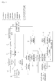
- Figure 1 is a schematic diagram showing a configuration according to one embodiment of a system for recycling waste tires for implementing a method for recycling waste tires according to the present invention, and reference numerals for main elements will be explained as below.
- Reference numeral 1 represents a pyrolysis furnace 1 which is an element for pyrolyzing by direct heating using a gas formed by mixing at least one component of carbon dioxide (CO 2 ), nitrogen (N 2 ), methane, ethane, propane, butane, pentane, hexane, ammonia, and argon as a carrier gas.
- the pyrolysis furnace 1 is provided at its top part with a throw-in port into which waste tires are inserted, provided at one part with an exhaust port through which the high temperature of vapor generated by the pyrolysis is circulated and an air exhaust port through which air is exhausted when initially operating, and provided at its bottom part with a discharge port through which pyrolyzed residues are discharged.
- Reference numeral 2 represents a residue processor provided at the bottom part of the discharge port in said pyrolysis furnace 1, the residue processor pulverizing the pyrolyzed residues.
- Reference numeral 3 represents a chain conveyor for separating pulverized carbon and iron core.
- Reference numeral 4 represents a carbon storage 4 and an iron core storage 5 for storing the carbon and iron-core separated by said chain conveyor 3, respectively.
- Reference numeral 6 represents a condenser for cooling and condensing the high temperature of vapor that is exhausted through the exhaust port of said pyrolysis furnace 1.
- Reference numeral 7 represents an oil tank for collecting oil separated in the cooling and condensing process.
- Reference numeral 8 represents a cyclone for collecting oil components that are not collected in the cooling and condensing process and are moving like gas together with a carrier gas.
- reference numeral 9 represents a third separator tank for directly contacting oil mist that has not been collected in said cyclone 8 with liquid oil aerationally to collect the oil mist.
- Reference numeral 10 represents a carbon incinerator in which carbon stored in said carbon storage 4 is transferred and incinerated by self-heating.
- Reference numeral 11 represents a first heat exchanger for receiving the high temperature of exhaust gas generated in said carbon incinerator 10, heating the cooled carrier gas at a high temperature, and then supplying the high temperature of carrier gas to said pyrolysis furnace 1.
- Reference numeral 12 represents a second heat exchanger for making high-pressure steam using the exhaust gas passing through said first heat exchanger 11.
- Reference numeral 13 represents a steam turbine for producing electricity using the high-pressure steam.
- Reference numeral 14 represents a freezer being supplied with low-pressure stream (about 5Kg/cm 2 ) that is used in and exhausted from said steam turbine 13 to produce and condense cold water.
- Reference numeral 15 represents a high-pressure pump for pumping condensation water to be circulated to said second heat exchanger 12.
- Reference numeral 16 represents a cleansing tower for cleaning exhaust gas that is exhausted from said second heat exchanger 12.
- Reference numeral 18 represents a blower.
- the pyrolysis furnace 1 is a factor for pyrolyzing waste tires by direct heating by being supplied with a noncondensable gas through a carrier gas circulation supply device 20 which will be described below and using the noncondensable gas as a carrier gas.
- the pyrolysis furnace 1 is provided with a throw-in port into which waste tires are inserted, a discharge port through which pyrolyzed residues are discharged, and an exhaust port through which the high temperature of vapor generated by the pyrolysis is exhausted. Air inside of the pyrolysis furnace 1 is exhausted outside by injection of the carrier gas, and the circulation exhaust port is open under a circumstance where the exhaust of the air has been completed so as to circulate the noncondensable gas generated in the combustion of waste tires.
- the circulation path of the noncondensable gas is represented by c1 in the Figure. That is, the heated vapor generated in the combustion of waste tires that are inserted into the pyrolysis furnace 1 passes the condenser 6, the cyclone 8 and the third separator tank 9, and then passes the blower 18 and the first heat exchanger 11 to be circulated to the pyrolysis furnace 1.
- Pyrolyzed residues processing means comprises a residue processor 2 being made of a pair of rollers and for carrying out pulverization on residues inserted therebetween, a chain conveyor 3 for separating pulverized carbon and iron core during the movement of the conveyor, and a carbon storage 4 and an iron core storage 5 for storing the carbon and iron core separated by said chain conveyor 3, respectively.
- Oil collection means is a factor for separating and extracting oil from the high temperature of vapor generated in the pyrolysis furnace 1, and comprises a condenser 6 for cooling and condensing the high temperature of vapor, an oil tank 7 for storing the oil first-separated by the cooling and condensation of the condenser 6, a cyclone 8 for second collecting aerial oil components by powerful vortex and transferring the collected oil components to said oil tank 7, and a third separator tank 9 for collecting the oil mist which has not been collected in the cyclone 8 by directly contacting the oil mist with liquid oil aerationally.
- the step of collecting oil aerationally could be excluded.
- Carbon processing means comprises a carbon incinerator 10 for incinerating carbon supplied from said carbon storage 4 to produce the high temperature of exhaust gas, first and second heat exchangers 11, 12 for heating the exhaust gas at a high temperature, a vapor turbine 13 being supplied with high pressure steam generated in the second heat exchange to produce electricity, an absorbing-type freezer 14 being supplied low pressure stream to produce condensate, and a high-pressure pump 15 for circulating the condensate to said second heat exchanger 12.
- Such configuration is similar to a configuration of a system for recycling waste tires, which was first-filed and patented by the present applicant.
- the present invention does not add a device or equipment for supplying and circulating a separate carrier gas made of carbon dioxide or nitrogen, but is characterized by additionally comprising a carrier gas circulation supply device 20 and an oxygen removing heating device 30 for collecting a noncondensable gas naturally generated in the combustion of waste tires to circulate and supply the noncondensable gas as a carrier gas, thereby increasing economical efficiency and yield of extracted oil.
- the carrier gas circulation supply device 20 of the present invention is connectively installed in a carrier gas circulation line c1.
- the carrier gas circulation line c1 refers to a path through which a carrier gas passes the pyrolysis furnace 1 and the oil collection means to be circulated to the pyrolysis furnace 1, and it is represented by reference numeral c1 in the Figures.
- the carrier gas circulation supply device 20 installed in the carrier gas circulation line c1 comprises sensing elements for measuring the temperature within the pyrolysis furnace 1 and the pressure within the carrier gas circulation line c1, and operates for collecting a noncondensable gas generated in the pyrolysis furnace 1 and storing the collected noncondensable gas, and then selectively circulating and supplying the stored noncondensable gas to the pyrolysis furnace 1.
- the carrier gas circulation supply device 20 comprises a pressure measuring unit 21 for measuring the internal pressure of the carrier gas circulation line c1, and a temperature measuring unit 23 for measuring the temperature within the pyrolysis furnace 1.
- the pressure measuring unit 21 and the temperature measuring unit 23 can be implemented by known mechanical or electronic sensors, and thus their detailed explanations are omitted.
- the carrier gas circulation supply device 20 comprises a noncondensable gas storage tank 27 being connected to the carrier gas circulation line c1 and selectively supplied with a noncondensable gas and storing it, and valves 25, 29 being installed in a pipeline connecting the noncondensable gas storage tank 27 and the carrier gas circulation line c1 and for selectively supplying the noncondensable gas to said noncondensable gas storage tank 27 and storing it or transferring the noncondensable gas stored in said noncondensable gas storage tank 27 to said carrier gas circulation line c1 to be supplied to said pyrolysis furnace 1.
- the carrier gas circulation supply device 20 uses the pressure measuring unit 21 and the temperature measuring unit 23, which are provided as the sensing elements, in order to determine if a noncondensable gas is generated in the combustion of waste tires that are inserted into the pyrolysis furnace 1.
- the pressure measuring unit 21 installed in the carrier gas circulation line c1 and measuring the internal pressure measures a preset value 100mmAq or higher
- the temperature measuring unit 23 for measuring the temperature inside of the pyrolysis furnace 1 measures a preset value 200°C or higher
- a valve corresponding to reference numeral 25 is off and a valve corresponding to reference numeral 29 is open so as to transfer the noncondensable gas stored in said noncondensable gas storage tank 27 to the carrier gas circulation line c1 to be supplied to said pyrolysis furnace 1.
- the present invention is characterized by additionally installing an oxygen removing heating device 30 in said carrier gas circulation line c1 in order to remove oxygen present in pyrolysis furnace 1.
- the oxygen removing heating device 30 is installed, the oxygen removing heating device 30 consisting of an electric heater comprising an electrothermal wire selectively heating by power supply or a heating element generating heat at a high temperature by being supplied with heat source of a heat exchanger.
- an electric heater comprising a thermal wire generating heat, preferably, at 300°C or higher may be used.
- Figure 2 is a flowchart for explaining a method for recycling waste tires according to the present invention.
- Figure 3 is a flowchart for explaining a method for operating a system for supplying a carrier gas outside in the method for recycling waste tires according to the present invention.
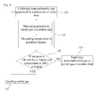
- Figure 4 is a flowchart for explaining an operating method for circulating and supplying a noncondensable gas generated in the combustion of waste tires as a carrier gas in the method for recycling waste tires according to the present invention.
- the method for recycling waste tires comprises: sealing the inside of the pyrolysis furnace 1 into which waste tires are inserted and injecting a carrier gas thereinto (S10); pyrolizing the waste tires by direct heating with the carrier gas injected into the pyrolysis furnace 1 (S20); and collecting oil by passing vapor generated in the pyrolysis step through at least one oil collection factor such as cooling, condensation, or centrifugal force (S30).
- the carrier gas injected into the pyrolysis furnace 1 passes the oil collection factor and a heat exchanger with vapor generated from the pyrolyzed tires to flow along the circulation line c1 through which the carrier gas is circulated to the pyrolysis furnace 1.
- the present invention suggests selectively supplying a carrier gas through the carrier gas supply device (50) comprising filler elements filled with a carrier gas formed by mixing at least one components of carbon dioxide, nitrogen, methane, ethane, propane, butane, pentane, hexane, ammonia, and argon to the pyrolysis furnace 1.
- the present invention when supplying the carrier gas formed by mixing at least one components of carbon dioxide, nitrogen, methane, ethane, propane, butane, pentane, hexane, ammonia, and argon, the present invention comprises: detecting oxygen through an oxygen detector installed in a carrier gas circulation line c1 (S11); determining if the oxygen is detected (S12); if the oxygen is detected, combusting to remove the oxygen in the carrier gas circulation line c1 (S13); and if the oxygen is not detected, supplying a carrier gas into the carrier gas circulation line c1 (S14).
- an oxygen detector is used, and for removing the oxygen, an electric heater generating heat by power supply or a heating element (heating coil) generating heat by being supplied with heat source of the heat exchange may be used.
- the present invention in the pryolysis step (S20), suggests a method for circulating and supplying a noncondensable gas generated in the combustion of waste tire as a carrier gas, not supplying a separate carrier gas from the outside, unlike Figure 3 .
- the present invention comprises: collecting a noncondensable gas generated in the combustion of waste tires in the pyrolysis furnace 1 to store the collected gas (S15); and measuring the pressure within the carrier gas circulation line c1 and the temperature within the pyrolysis furnance 1, and if the measurements are a preset value or higher, collecting the noncondensable gas to store the collected gas, and if the measurements are less than a preset value, supplying the stored noncondensable gas to the carrier gas circulation line c1 (S18).
- the present invention collects a noncondensable gas flowing in the carrier gas circulation line c1 to store the controlled gas if the pressure in the carrier gas circulation line is 100 mmAq or higher and the temperature within the pyrolysis furnace 1 is 200°C or higher, or supplies the collected and stored carrier gas in the carrier gas circulation line c1 if the pressure and temperature are less than a preset value.
- the step of collecting oil consecutively passes the following steps: a first oil collection comprising a condenser being supplied with vapor generated by the combustion of waste tires and cooling and condensing the vapor to transfer the cooled and condensed vapor to an oil tank (S31); and a second oil collection comprising one or more cyclones collecting oil from supplied vapor that has not been collected in the first oil collection or oil mist consisting of small oil particles through centrifugal force to transfer the collected oil to the oil tank (S32).
- a first oil collection comprising a condenser being supplied with vapor generated by the combustion of waste tires and cooling and condensing the vapor to transfer the cooled and condensed vapor to an oil tank (S31); and a second oil collection comprising one or more cyclones collecting oil from supplied vapor that has not been collected in the first oil collection or oil mist consisting of small oil particles through centrifugal force to transfer the collected oil to the oil tank (S32).
- the present invention suggests further comprising: residues of the waste tires that were put into the pyrolysis furnace 1 and pyrolyzed being eliminated outside to be pulverized and discharged by residue treatment step (S25).
Landscapes
- Chemical & Material Sciences (AREA)
- Engineering & Computer Science (AREA)
- Oil, Petroleum & Natural Gas (AREA)
- Organic Chemistry (AREA)
- Life Sciences & Earth Sciences (AREA)
- Chemical Kinetics & Catalysis (AREA)
- Environmental & Geological Engineering (AREA)
- Mechanical Engineering (AREA)
- Sustainable Development (AREA)
- Thermal Sciences (AREA)
- Physics & Mathematics (AREA)
- Health & Medical Sciences (AREA)
- Materials Engineering (AREA)
- Medicinal Chemistry (AREA)
- Polymers & Plastics (AREA)
- Wood Science & Technology (AREA)
- General Chemical & Material Sciences (AREA)
- Production Of Liquid Hydrocarbon Mixture For Refining Petroleum (AREA)
- Separation, Recovery Or Treatment Of Waste Materials Containing Plastics (AREA)
- Gasification And Melting Of Waste (AREA)
Applications Claiming Priority (2)
| Application Number | Priority Date | Filing Date | Title |
|---|---|---|---|
| KR20080120486A KR101026859B1 (ko) | 2008-12-01 | 2008-12-01 | 폐타이어 재활용 방법 |
| PCT/KR2009/006886 WO2010064800A2 (fr) | 2008-12-01 | 2009-11-23 | Procédé de recyclage de pneus usés |
Publications (2)
| Publication Number | Publication Date |
|---|---|
| EP2384872A2 true EP2384872A2 (fr) | 2011-11-09 |
| EP2384872A4 EP2384872A4 (fr) | 2013-09-04 |
Family
ID=42233702
Family Applications (1)
| Application Number | Title | Priority Date | Filing Date |
|---|---|---|---|
| EP09830538.6A Withdrawn EP2384872A4 (fr) | 2008-12-01 | 2009-11-23 | Procédé de recyclage de pneus usés |
Country Status (9)
| Country | Link |
|---|---|
| US (1) | US20110284358A1 (fr) |
| EP (1) | EP2384872A4 (fr) |
| KR (1) | KR101026859B1 (fr) |
| CN (1) | CN102232012A (fr) |
| AR (1) | AR074444A1 (fr) |
| BR (1) | BRPI0917040A2 (fr) |
| CA (1) | CA2744752A1 (fr) |
| TW (1) | TW201028225A (fr) |
| WO (1) | WO2010064800A2 (fr) |
Families Citing this family (5)
| Publication number | Priority date | Publication date | Assignee | Title |
|---|---|---|---|---|
| EP2212007A1 (fr) * | 2007-10-16 | 2010-08-04 | BlackCarbon A/S | Procédé et appareil pour absorption du méthane et procédé permettant de déterminer un crédit de pollution |
| SE538794C2 (sv) * | 2014-05-20 | 2016-11-29 | Ses Ip Ab C/O Scandinavian Enviro Systems Ab | Anläggning och förfarande för återvinning av kol och kolväteföreningar från organiskt insatsmaterial genom pyrolys. |
| FR3037130B1 (fr) * | 2015-06-05 | 2017-06-16 | Lepez Conseils Finance Innovations Lcfi | Four de craquage |
| CN112552944B (zh) * | 2020-03-23 | 2022-07-22 | 苏州双福智能科技有限公司 | 一种废旧轮胎热裂解回收用废气处理装置 |
| CN112207112B (zh) * | 2020-09-09 | 2021-12-03 | 北京汇潮云集科技有限公司 | 一种垃圾热解发电装置 |
Family Cites Families (18)
| Publication number | Priority date | Publication date | Assignee | Title |
|---|---|---|---|---|
| DE2658371C2 (de) * | 1976-12-23 | 1983-03-03 | Carl Robert Eckelmann AG, 2000 Hamburg | Verfahren zum Pyrolysieren von Altreifen |
| US4260473A (en) * | 1979-05-03 | 1981-04-07 | Occidental Research Corporation | Removal of particulates from pyrolytic oil |
| IT1178901B (it) * | 1984-03-22 | 1987-09-16 | Irfin S P A | Procedimento per il recupero selettivo dei materiali costituenti cascami di cavi elettrici isolati |
| KR0155064B1 (ko) * | 1994-03-30 | 1998-11-16 | 이현희 | 폐타이어의 열분해에 의한 가스추출방법 및 장치 |
| JPH08159430A (ja) * | 1994-12-02 | 1996-06-21 | Kobe Steel Ltd | ゴム系廃棄物の燃焼処理方法 |
| US5730069A (en) * | 1995-10-30 | 1998-03-24 | Tek-Kol | Lean fuel combustion control method |
| JPH09286990A (ja) * | 1996-04-23 | 1997-11-04 | Yoichi Wada | 廃タイヤの熱分解方法及びその装置 |
| KR100362246B1 (ko) * | 1997-06-18 | 2003-02-05 | 주식회사 엘지화학 | 고분자 폐기물의 열분해 처리장치 |
| SE513063C2 (sv) * | 1998-08-21 | 2000-06-26 | Bengt Sture Ershag | Förfarande vid återvinning av kol och kolväteföreningar från polymeriskt material, företrädesvis i form av kasserade däck, genom pyrolys i en pyrolysreaktor |
| JP3413136B2 (ja) * | 1999-10-25 | 2003-06-03 | 汎洋興業株式会社 | 廃タイヤの再生処理方法および廃タイヤ再生処理装置 |
| BG65901B1 (bg) * | 2005-05-09 | 2010-04-30 | КОЛЕВ Димитър | Метод и инсталация за пиролиз на автомобилни гуми |
| CN100441664C (zh) * | 2005-11-16 | 2008-12-10 | 张展洪 | 金属浴裂解废轮胎橡胶、塑料制取锅炉燃料的方法 |
| KR100628890B1 (ko) * | 2006-05-26 | 2006-09-27 | 주식회사 에이쓰 | 폐타이어의 재활용 시스템 |
| CN1883828A (zh) * | 2006-07-03 | 2006-12-27 | 李康敏 | 带包皮金属含金属膜贴片热力气化回收处理方法及设备 |
| WO2008075931A1 (fr) * | 2006-12-20 | 2008-06-26 | Rodriguez Hernandez Jesus Edua | Système et procédé d'obtention d'hydrocarbures à partir de déchets solides organiques et inorganiques |
| EP2085456A3 (fr) * | 2008-01-30 | 2009-12-16 | Wilson, Paul | Appareil de décomposition par pyrolyse et son utilisation et procédé pour décomposer des substances organiques par pyrolyse |
| KR100914917B1 (ko) * | 2008-09-24 | 2009-08-31 | 주식회사 에이쓰 | 폐타이어 재활용 시스템 |
| KR100937214B1 (ko) * | 2008-10-08 | 2010-01-20 | 주식회사 에이쓰 | 폐타이어 재활용 시스템 |
-
2008
- 2008-12-01 KR KR20080120486A patent/KR101026859B1/ko not_active Expired - Fee Related
-
2009
- 2009-11-23 CN CN2009801480338A patent/CN102232012A/zh active Pending
- 2009-11-23 EP EP09830538.6A patent/EP2384872A4/fr not_active Withdrawn
- 2009-11-23 WO PCT/KR2009/006886 patent/WO2010064800A2/fr not_active Ceased
- 2009-11-23 US US13/132,319 patent/US20110284358A1/en not_active Abandoned
- 2009-11-23 CA CA2744752A patent/CA2744752A1/fr not_active Abandoned
- 2009-11-23 BR BRPI0917040A patent/BRPI0917040A2/pt not_active IP Right Cessation
- 2009-12-01 TW TW98141007A patent/TW201028225A/zh unknown
- 2009-12-01 AR ARP090104634 patent/AR074444A1/es not_active Application Discontinuation
Also Published As
| Publication number | Publication date |
|---|---|
| TW201028225A (en) | 2010-08-01 |
| CA2744752A1 (fr) | 2010-06-10 |
| EP2384872A4 (fr) | 2013-09-04 |
| WO2010064800A2 (fr) | 2010-06-10 |
| KR101026859B1 (ko) | 2011-04-06 |
| WO2010064800A3 (fr) | 2010-09-16 |
| BRPI0917040A2 (pt) | 2016-02-16 |
| AR074444A1 (es) | 2011-01-19 |
| US20110284358A1 (en) | 2011-11-24 |
| KR20100062066A (ko) | 2010-06-10 |
| CN102232012A (zh) | 2011-11-02 |
Similar Documents
| Publication | Publication Date | Title |
|---|---|---|
| KR100914917B1 (ko) | 폐타이어 재활용 시스템 | |
| CA2739816C (fr) | Systeme de recyclage de pneumatiques usages | |
| EP2384872A2 (fr) | Procédé de recyclage de pneus usés | |
| US4126000A (en) | System for treating and recovering energy from exhaust gases | |
| CN102424868B (zh) | 一种高炉熔渣水淬废汽余热回收系统 | |
| CN101466779B (zh) | 废轮胎回收系统 | |
| CN108018062A (zh) | 废旧橡胶裂解方法及系统 | |
| US20120066963A1 (en) | Device for preparing bio-oil, system for preparing bio-oil and method for preparing bio-oil using the same | |
| KR102353315B1 (ko) | 폐 수지 연속식 열분해기 및 그 열분해기를 포함하는 폐 수지 연속식 유화 플랜트 시스템 | |
| GB1564450A (en) | System for treating and recovering energy from exhaust gases | |
| CA2479985A1 (fr) | Systeme ameliore de conversion energetique a partir d'un flux de fluide thermique | |
| OA16568A (en) | System for recycling used tires. | |
| KR101529165B1 (ko) | 폐타이어 처리 및 배열회수가 가능한 복합 발전 플랜트 | |
| KR101140553B1 (ko) | 러버 스크랩 및 러버 플레이크의 열적 성분 분해 시스템 | |
| KR20050104324A (ko) | 폐합성수지를 이용한 터널식 열분해유 재생장치 | |
| CN105890375A (zh) | 冶金炉烟气余热利用除尘方法 | |
| CN104075580A (zh) | 半密闭电炉烟气余热发电方法 | |
| CN105300119A (zh) | 全密闭电炉烟气余热利用方法 | |
| CN105318727A (zh) | 冶金炉烟气余热利用方法 | |
| CN104764331A (zh) | 电炉烟气有机朗肯余热发电方法 | |
| CN105890387A (zh) | 冶金全密闭电炉烟气节能除尘方法 |
Legal Events
| Date | Code | Title | Description |
|---|---|---|---|
| PUAI | Public reference made under article 153(3) epc to a published international application that has entered the european phase |
Free format text: ORIGINAL CODE: 0009012 |
|
| 17P | Request for examination filed |
Effective date: 20110530 |
|
| AK | Designated contracting states |
Kind code of ref document: A2 Designated state(s): AT BE BG CH CY CZ DE DK EE ES FI FR GB GR HR HU IE IS IT LI LT LU LV MC MK MT NL NO PL PT RO SE SI SK SM TR |
|
| DAX | Request for extension of the european patent (deleted) | ||
| A4 | Supplementary search report drawn up and despatched |
Effective date: 20130801 |
|
| RIC1 | Information provided on ipc code assigned before grant |
Ipc: C08J 11/00 20060101ALI20130726BHEP Ipc: B29B 17/00 20060101AFI20130726BHEP |
|
| STAA | Information on the status of an ep patent application or granted ep patent |
Free format text: STATUS: THE APPLICATION IS DEEMED TO BE WITHDRAWN |
|
| 18D | Application deemed to be withdrawn |
Effective date: 20140301 |