EP2385217A2 - Eléments asymétriques de connexion entre des pales voisines pour l'amortissement des vibrations - Google Patents
Eléments asymétriques de connexion entre des pales voisines pour l'amortissement des vibrations Download PDFInfo
- Publication number
- EP2385217A2 EP2385217A2 EP11165003A EP11165003A EP2385217A2 EP 2385217 A2 EP2385217 A2 EP 2385217A2 EP 11165003 A EP11165003 A EP 11165003A EP 11165003 A EP11165003 A EP 11165003A EP 2385217 A2 EP2385217 A2 EP 2385217A2
- Authority
- EP
- European Patent Office
- Prior art keywords
- mid
- blade
- radial position
- span structure
- span
- Prior art date
- Legal status (The legal status is an assumption and is not a legal conclusion. Google has not performed a legal analysis and makes no representation as to the accuracy of the status listed.)
- Withdrawn
Links
- 238000013016 damping Methods 0.000 title 1
- 230000008878 coupling Effects 0.000 claims abstract description 7
- 238000010168 coupling process Methods 0.000 claims abstract description 7
- 238000005859 coupling reaction Methods 0.000 claims abstract description 7
- 230000013011 mating Effects 0.000 claims description 17
- 238000012986 modification Methods 0.000 description 4
- 230000004048 modification Effects 0.000 description 4
- 239000012530 fluid Substances 0.000 description 3
- 239000000463 material Substances 0.000 description 3
- 229910000831 Steel Inorganic materials 0.000 description 1
- RTAQQCXQSZGOHL-UHFFFAOYSA-N Titanium Chemical compound [Ti] RTAQQCXQSZGOHL-UHFFFAOYSA-N 0.000 description 1
- 238000004873 anchoring Methods 0.000 description 1
- 238000005266 casting Methods 0.000 description 1
- 230000000295 complement effect Effects 0.000 description 1
- 238000000034 method Methods 0.000 description 1
- 239000010959 steel Substances 0.000 description 1
- 229910052719 titanium Inorganic materials 0.000 description 1
- 239000010936 titanium Substances 0.000 description 1
- 238000003466 welding Methods 0.000 description 1
Images




Classifications
-
- F—MECHANICAL ENGINEERING; LIGHTING; HEATING; WEAPONS; BLASTING
- F01—MACHINES OR ENGINES IN GENERAL; ENGINE PLANTS IN GENERAL; STEAM ENGINES
- F01D—NON-POSITIVE DISPLACEMENT MACHINES OR ENGINES, e.g. STEAM TURBINES
- F01D5/00—Blades; Blade-carrying members; Heating, heat-insulating, cooling or antivibration means on the blades or the members
- F01D5/12—Blades
- F01D5/22—Blade-to-blade connections, e.g. for damping vibrations
-
- F—MECHANICAL ENGINEERING; LIGHTING; HEATING; WEAPONS; BLASTING
- F05—INDEXING SCHEMES RELATING TO ENGINES OR PUMPS IN VARIOUS SUBCLASSES OF CLASSES F01-F04
- F05D—INDEXING SCHEME FOR ASPECTS RELATING TO NON-POSITIVE-DISPLACEMENT MACHINES OR ENGINES, GAS-TURBINES OR JET-PROPULSION PLANTS
- F05D2250/00—Geometry
- F05D2250/30—Arrangement of components
- F05D2250/34—Arrangement of components translated
-
- F—MECHANICAL ENGINEERING; LIGHTING; HEATING; WEAPONS; BLASTING
- F05—INDEXING SCHEMES RELATING TO ENGINES OR PUMPS IN VARIOUS SUBCLASSES OF CLASSES F01-F04
- F05D—INDEXING SCHEME FOR ASPECTS RELATING TO NON-POSITIVE-DISPLACEMENT MACHINES OR ENGINES, GAS-TURBINES OR JET-PROPULSION PLANTS
- F05D2260/00—Function
- F05D2260/96—Preventing, counteracting or reducing vibration or noise
Definitions
- the disclosure relates generally to bladed wheels, and more particularly, to a blade for a bladed wheel having asymmetrical mid-span structure portions and a related bladed wheel structure.
- bladed wheels for industrial purposes, it is necessary to ensure that the structure can withstand a range of operating frequencies.
- Such bladed wheels may be employed in machines such as fans, compressors, turbines, etc.
- adjacent blades 10 are commonly connected by one or more sets of circumferentially extending mid-span structures 12.
- Each set and each individual mid-span structure 12 extends at a uniform radial position R throughout the bladed wheel relative to a hub 14 thereof.
- the number, size and radial position of mid-span structures 12 are some of the main factors that impact bladed wheel frequencies and must be detuned to handle critical resonant crossings for all operational modes of interest.
- a first aspect of the disclosure provides a bladed wheel structure comprising: a bladed wheel including a plurality of circumferentially spaced blades extending from a hub; and a set of mid-span structures coupling adjacent blades of the plurality of circumferentially spaced blades, wherein the set of mid-span structures are positioned in a non-uniform radial position arrangement.
- a second aspect of the disclosure provides a blade comprising: a body including an airfoil section; a root at an end of the body for coupling the blade to a hub; a first mid-span structure portion extending from the body; and a second mid-span structure portion extending from the body, wherein the first and second mid-span structure portions extend from the body in an asymmetrical manner.
- each structure 100, 200 includes a bladed wheel 102 including a plurality of circumferentially spaced blades 110, 210 extending from a hub 112.
- Each blade 110, 210 includes a body 120 including an airfoil section 122, e.g., along the length of body 120, and a root 124 at an end of body 120 for coupling blade 110 to hub 112.
- airfoil section 122 and root 124 may take a variety of forms depending on the application for blades 110, 210.
- hub 112 is coupled to a rotating shaft (not shown) to either create rotation therein by a fluid passing over blades 110, 210, or creating a fluid flow by rotation of blades 110, 210 by forced rotation of the rotating shaft.
- a rotating shaft not shown
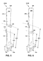
- Each blade 110, 210 as shown in FIG. 3 and FIGS. 5-6 , may include a cover or integral cover 140, although this may not be necessary for all applications.
- modifications of mid-span structures are oftentimes the focus of detuning resonant frequencies of a bladed wheel.
- the modifications include increasing the number or size of mid-span structures and/or varying the uniform radial position of the mid-span structures. Increasing the number and size increases the total mass and makes the design more complex, and varying the uniform radial position of the mid-span structures does not necessarily detune critical resonant crossings for all operational modes of interest.
- embodiments of the invention provide a set of mid-span structures 130 ( FIGS. 2 and 3 ) and 230, 232 ( FIGS. 4-6 ), each extending between adjacent circumferentially spaced blades 110, 210, respectively.
- embodiments of the invention provide set of mid-span structures 130 and 230, 232 positioned in a non-uniform radial position arrangement. That is, in contrast to mid-span structures 12, shown in FIG. 1 , mid-span structures 130 and 230, 232 are not all positioned at a uniform radial position relative to hub 112.
- the non-uniform radial position arrangement may be configured to detune resonant frequency vibrations.
- the non-uniform radial position arrangement of structure 100 includes each mid-span structure 130 extending radially obliquely relative to each adjacent blade 110.
- This radially oblique angling is in contrast to, or in addition to, an oblique angle of attack that each mid-span structure 130 may have relative to a fluid passing thereby, i.e., into and out of the page of FIGS. 2 and 3 .
- each mid-span structure 130 includes a first end 132 having a first radial position R1 relative to hub 112 on a first blade (e.g., 110A) and a second end 134 having a second radial position R2 relative to hub 112 different than first radial position R1 on a second blade (e.g., 110B) that is adjacent to first blade (e.g., 110A). Consequently, the radial position of each mid-span structure 130 relative to hub 112 varies between adjacent blades 110. This arrangement repeats between each pair of adjacent blades about hub 112.
- An advantage that may be realized in the practice of some embodiments of the described structure 100 is that radial positions R1 and R2 may be modified to detune the resonant frequencies of bladed wheel 102. Consequently, the radially oblique angling of mid-span structures 130 provide another feature that can be modified for detuning purposes.
- Mid-span structures 130 may be positioned practically anywhere along blades 110, and have any of a variety of oblique angles relative to blades 110.
- the non-uniform radial position arrangement of structure 200 includes a first mid-span structure 230 positioned at a first radial position R3 relative to hub 112 between a first blade 210A and a second blade 210B adjacent to first blade 210A.
- a second mid-span structure 232 may be positioned at a second radial position R4 relative to hub 112 different than first radial position R1 between first blade 210A and a third blade 210C adjacent to first blade 210A.
- each mid-span structure 230, 232 has a substantially uniform radial position between respective adjacent blades 210.
- An advantage that may be realized in the practice of some embodiments of the described structure 200 is that radial positions R3 and R4 may be modified to detune the resonant frequencies of bladed wheel 102. Consequently, having mid-span structures 230, 232 of adjacent pairs of blades at different radial positions provides another feature that can be modified for detuning purposes. Mid-span structures 230, 232 may be positioned practically anywhere along blades 210.
- each blade 110, 210 may be manufactured using any now known or later developed technique, e.g., casting with conventional fmishing, and may be made of any conventional material such as steel, titanium, etc.
- each mid-span structure 130 ( FIG. 2 ) and 230, 232 ( FIG. 4 ) may be formed using mating portions, which may be helpful for, e.g., assembly and/or replacement purposes. More specifically, as shown in FIG. 3 for the FIG. 2 embodiment, for example, each mid-span structure 130 ( FIG. 2 ) may include a first mid-span structure portion 140 on one blade 110 capable of mating with a complementary mid-span structure portion 142 of an adjacent blade.
- each mid-span structure 230 or 232 may include a first mid-span structure portion 240 on one blade 110 capable of mating with a complimentary mid-span structure portion 242 of an adjacent blade. That is, each blade 110, 210 includes first mid-span structure portion 140, 240 extending from body 120, and second mid-span structure portion 142, 242 extending from body 120. In one embodiment, each blade 110 includes only first mid-span structure portion 140, 240 and second mid-span structure portion 142, 242 extending from a mid-span section (i.e., anywhere along body 120) of blade 110, 210.
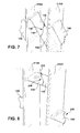
- FIGS. 7 and 8 Illustrative configurations of how portions 140, 142 and 240, 242 mate are illustrated in FIGS. 7 and 8 , respectively.
- a mating zig-zag surface configuration 146 ( FIG. 7 ) and 246 ( FIG. 8 ) is employed. It is understood that there exists a myriad of different manners of mating mid-span structure portions known in the art, and all are included within the scope of the invention.
- first and second mid-span structure portions 140, 240 and 142, 242 extend from body 120 in an asymmetrical manner.
- Conventional blades may include differently shaped mid-span structure portions that accommodate mating, similarly to the mating surface configurations 146, 246 shown in FIGS. 7 and 8 , respectively, but the mid-span structure portions extend symmetrically from each blade, i.e., from substantially the same radial position on opposite sides of the blade. For example, as shown in FIG. 1 , they extend at a uniform radial position relative to hub 14 (or the root of the blade) and perhaps with some minor radial inward tilt to accommodate mating.
- blades 110, 210 in contrast to conventional blades, have mid-span structure portions 140, 240 and 142, 242 extending asymmetrically from body 120, i.e., from different radial positions on each side of the blade.
- first mid-span structure portion 140 includes a longitudinal axis L1 that extends at an oblique angle from a first side 150 of body 120
- second mid-span structure portion 142 includes a longitudinal axis L2 that extends at an oblique angle from a second side 152 of body 120 such that the first and second mid-span structure portions 140, 142 of adjacent blades mate, as shown in FIG. 2
- first mid-span structure portion 140 may include a first end having a first radial position R11 relative to hub 112 ( FIG.
- second mid-span structure portion 142 may include a first end having a third radial position R13 relative to hub 112 (or root 124 thereof) and a second end having a fourth radial position R14 relative to hub 112 (or root 124 thereof) that is different than third radial position R13.
- first radial position R11 of the first end of first mid-span structure portion 140 is greater than fourth radial position R14 of the second end of second mid-span structure portion 142, and second radial position R12 and third radial position R13 are substantially equal, so as to accommodate mating.
- the oblique angles and radial positions in which first and second mid-span structure portions 140, 142 extend from body 120 may be configured to detune resonant frequency vibrations.
- each mating blade 210A ( FIG. 5 ) and 210B ( FIG. 6 ) includes a first mid-span structure portion 240 extending from a first side 250 of body 120 at a first radial position R21, and second mid-span structure portion 242 extending from a second side 252 of body 120 at a second radial position R22 different than first radial position R21.
- each mid-span structure portion 240, 242 is configured for mating with one of a mating portion 242, 240, respectively, of the respective mid-span structure on an adjacent blade.
- First and second radial positions R21, R22 can be configured to detune resonant frequency vibrations.
- each mid-span structure portion 240, 242 may simply mate with body 120 of an adjacent blade. It is understood that this embodiment does not appear any differently than FIGS. 4-6 , except the mating surface configurations of FIG. 7 and 8 would not be necessary as the end of each portion would simply mate with body 120.
- FIG. 9 shows an example of a combination of the embodiments described.
- a set of mid-span structures 130 FIGS. 2 and 3
- 230, 232 FIGS. 4-6
- each mid-span structure includes a wire 360, 460 that extends through openings 362, 462 in respective adjacent blades 110, 210.
- Wire 360 as shown in FIG. 10 , may include bends 361 to accommodate the radially oblique angling between adjacent blades 110.
- Each wire may include an anchor 364, 464 to hold the respective ends in place.
- each anchor 364, 464 includes an enlarged end on each wire that is positioned in a seat 366, 466; however, any other mechanism of anchoring a wire may be employed, e.g., threaded bolts, welding, etc.
Landscapes
- Engineering & Computer Science (AREA)
- Mechanical Engineering (AREA)
- General Engineering & Computer Science (AREA)
- Structures Of Non-Positive Displacement Pumps (AREA)
- Turbine Rotor Nozzle Sealing (AREA)
Applications Claiming Priority (1)
| Application Number | Priority Date | Filing Date | Title |
|---|---|---|---|
| RU2010117972/06A RU2010117972A (ru) | 2010-05-06 | 2010-05-06 | Облопаченное колесо и лопатка |
Publications (1)
| Publication Number | Publication Date |
|---|---|
| EP2385217A2 true EP2385217A2 (fr) | 2011-11-09 |
Family
ID=44168466
Family Applications (1)
| Application Number | Title | Priority Date | Filing Date |
|---|---|---|---|
| EP11165003A Withdrawn EP2385217A2 (fr) | 2010-05-06 | 2011-05-05 | Eléments asymétriques de connexion entre des pales voisines pour l'amortissement des vibrations |
Country Status (4)
| Country | Link |
|---|---|
| US (1) | US20110274549A1 (fr) |
| EP (1) | EP2385217A2 (fr) |
| JP (1) | JP2011236898A (fr) |
| RU (1) | RU2010117972A (fr) |
Cited By (3)
| Publication number | Priority date | Publication date | Assignee | Title |
|---|---|---|---|---|
| WO2014048549A3 (fr) * | 2012-09-28 | 2014-08-07 | Ihi Charging Systems International Gmbh | Roue à aubes permettant de déterminer le comportement vibratoire des aubes de roue, banc d'essai permettant de déterminer le comportement vibratoire d'aubes de roue, et procédé permettant de déterminer le comportement vibratoire d'aubes de roue |
| EP2910737A1 (fr) * | 2014-02-21 | 2015-08-26 | Rolls-Royce plc | Rotor pour une turbomachine et procédé associé |
| WO2018169668A1 (fr) * | 2017-03-13 | 2018-09-20 | Siemens Aktiengesellschaft | Pales amortisseurs ayant une résistance au flottement améliorée |
Families Citing this family (3)
| Publication number | Priority date | Publication date | Assignee | Title |
|---|---|---|---|---|
| US20150089809A1 (en) * | 2013-09-27 | 2015-04-02 | General Electric Company | Scaling to custom-sized turbomachine airfoil method |
| WO2018169665A1 (fr) * | 2017-03-13 | 2018-09-20 | Siemens Aktiengesellschaft | Pales carénées à résistance au flottement améliorée |
| KR102468297B1 (ko) * | 2020-09-25 | 2022-11-16 | 두산에너빌리티 주식회사 | 향상된 댐핑 성능을 갖는 터빈 블레이드 |
Family Cites Families (22)
| Publication number | Priority date | Publication date | Assignee | Title |
|---|---|---|---|---|
| US1618285A (en) * | 1927-02-22 | Blade lashing | ||
| US791743A (en) * | 1905-03-18 | 1905-06-06 | Westinghouse Machine Co | Elastic-fluid turbine. |
| US791735A (en) * | 1905-03-18 | 1905-06-06 | Westinghouse Machine Co | Elastic-fluid turbine. |
| US791744A (en) * | 1905-03-22 | 1905-06-06 | Westinghouse Machine Co | Elastic-fluid turbine. |
| US1068512A (en) * | 1913-01-31 | 1913-07-29 | Ljungstroems Angturbin Ab | Blade-rings of radial turbines. |
| US1253834A (en) * | 1916-12-08 | 1918-01-15 | Gen Electric | Elastic-fluid turbine. |
| US1618284A (en) * | 1925-05-22 | 1927-02-22 | Westinghouse Electric & Mfg Co | Turbine-blade bracing |
| US1621618A (en) * | 1925-07-24 | 1927-03-22 | Westinghouse Electric & Mfg Co | Turbine-blade lashing |
| US1888795A (en) * | 1929-07-18 | 1932-11-22 | Faber Paul | Turbine blade lashing |
| US2361676A (en) * | 1939-05-15 | 1944-10-31 | Lin E Baker | Device for impelling and propelling fluid or gas or the like |
| US2771267A (en) * | 1952-05-27 | 1956-11-20 | United Aircraft Corp | Lacing for compressor blades |
| US3045969A (en) * | 1958-09-26 | 1962-07-24 | Escher Wyss Ag | Vibration damping device for turbo-machine |
| GB1309646A (en) * | 1970-04-10 | 1973-03-14 | Secr Defence | Bladed rotor for a gas turbine engine |
| JPS5395406A (en) * | 1977-02-02 | 1978-08-21 | Hitachi Ltd | Connection structure for vane |
| JPS572405A (en) * | 1980-06-05 | 1982-01-07 | Hitachi Ltd | Rotary blade connector of axial-flow rotary machine |
| JPS5799213A (en) * | 1981-08-10 | 1982-06-19 | Mitsubishi Heavy Ind Ltd | Production of group of vanes for rotary machine |
| JPS6149103A (ja) * | 1984-08-16 | 1986-03-11 | Toshiba Corp | タ−ビン動翼連結装置 |
| US5257908A (en) * | 1991-11-15 | 1993-11-02 | Ortolano Ralph J | Turbine lashing structure |
| JP3107266B2 (ja) * | 1993-09-17 | 2000-11-06 | 株式会社日立製作所 | 流体機械および流体機械の翼装置 |
| US5540551A (en) * | 1994-08-03 | 1996-07-30 | Westinghouse Electric Corporation | Method and apparatus for reducing vibration in a turbo-machine blade |
| WO1999013200A1 (fr) * | 1997-09-05 | 1999-03-18 | Hitachi, Ltd. | Turbine a vapeur |
| TWI286184B (en) * | 2005-12-02 | 2007-09-01 | Delta Electronics Inc | Fan and impeller thereof |
-
2010
- 2010-05-06 RU RU2010117972/06A patent/RU2010117972A/ru not_active Application Discontinuation
- 2010-11-09 US US12/942,275 patent/US20110274549A1/en not_active Abandoned
-
2011
- 2011-04-21 JP JP2011094587A patent/JP2011236898A/ja not_active Withdrawn
- 2011-05-05 EP EP11165003A patent/EP2385217A2/fr not_active Withdrawn
Non-Patent Citations (1)
| Title |
|---|
| None |
Cited By (5)
| Publication number | Priority date | Publication date | Assignee | Title |
|---|---|---|---|---|
| WO2014048549A3 (fr) * | 2012-09-28 | 2014-08-07 | Ihi Charging Systems International Gmbh | Roue à aubes permettant de déterminer le comportement vibratoire des aubes de roue, banc d'essai permettant de déterminer le comportement vibratoire d'aubes de roue, et procédé permettant de déterminer le comportement vibratoire d'aubes de roue |
| EP2910737A1 (fr) * | 2014-02-21 | 2015-08-26 | Rolls-Royce plc | Rotor pour une turbomachine et procédé associé |
| US10145247B2 (en) | 2014-02-21 | 2018-12-04 | Rolls-Royce Plc | Rotor for a turbo-machine and a related method |
| WO2018169668A1 (fr) * | 2017-03-13 | 2018-09-20 | Siemens Aktiengesellschaft | Pales amortisseurs ayant une résistance au flottement améliorée |
| CN110382824A (zh) * | 2017-03-13 | 2019-10-25 | 西门子股份公司 | 具有经改进的抗颤振性的带缓冲器的叶片 |
Also Published As
| Publication number | Publication date |
|---|---|
| RU2010117972A (ru) | 2011-11-20 |
| JP2011236898A (ja) | 2011-11-24 |
| US20110274549A1 (en) | 2011-11-10 |
Similar Documents
| Publication | Publication Date | Title |
|---|---|---|
| EP2385217A2 (fr) | Eléments asymétriques de connexion entre des pales voisines pour l'amortissement des vibrations | |
| EP1741878B1 (fr) | Turbomachine | |
| JP5230968B2 (ja) | 動翼振動ダンパシステム | |
| EP2372165B1 (fr) | Structure d'aube de stator et turbine à gaz | |
| US8231352B2 (en) | Vibration damper assembly | |
| KR101650977B1 (ko) | 댐핑 장치를 구비하고 언튠드 블레이드를 갖춘 터빈 휠 | |
| EP2013449B1 (fr) | Ventilateur axial avec aubes de stator ayant une cambrure dans le sens de la corde et dans le sens de l'envergure | |
| EP2339115A2 (fr) | Ensemble de rotor de turbine et turbine à vapeur | |
| US9341067B2 (en) | Blade arrangement and associated gas turbine | |
| EP2146119A1 (fr) | Dispositif d'étanchéité | |
| EP3623638B1 (fr) | Ventilateur hélicoïdal | |
| JP6362873B2 (ja) | 合成接触角を有するタービンブレード先端シュラウド及びミッドスパンスナバ | |
| US20040191068A1 (en) | Moving-blade row for fluid-flow machines | |
| JP6370984B2 (ja) | 可変ノズル機構及び可変容量型排気ターボ過給機 | |
| JP6278447B2 (ja) | 液体ダンパ、及びこれを備えた回転機械翼 | |
| EP2803821A1 (fr) | Dispositif d'aube, système d'aubes et procédé de fabrication associé d'un système d'aubes | |
| US10526896B2 (en) | Turbomachine blade assembly | |
| JP6278448B2 (ja) | 液体ダンパ、及びこれを備えた回転機械翼 | |
| KR20010101664A (ko) | 균형용 클립 | |
| US7654793B2 (en) | Fan shroud supports which increase resonant frequency | |
| US6676380B2 (en) | Turbine blade assembly with pin dampers | |
| US7572098B1 (en) | Vane ring with a damper | |
| JP6745235B2 (ja) | ロータ及びこのロータを備える回転機械 | |
| JP4565006B2 (ja) | ブレードおよびこのブレードを備えたファン | |
| US9151163B2 (en) | Turbomachine rotor disk |
Legal Events
| Date | Code | Title | Description |
|---|---|---|---|
| AK | Designated contracting states |
Kind code of ref document: A2 Designated state(s): AL AT BE BG CH CY CZ DE DK EE ES FI FR GB GR HR HU IE IS IT LI LT LU LV MC MK MT NL NO PL PT RO RS SE SI SK SM TR |
|
| AX | Request for extension of the european patent |
Extension state: BA ME |
|
| PUAI | Public reference made under article 153(3) epc to a published international application that has entered the european phase |
Free format text: ORIGINAL CODE: 0009012 |
|
| STAA | Information on the status of an ep patent application or granted ep patent |
Free format text: STATUS: THE APPLICATION IS DEEMED TO BE WITHDRAWN |
|
| 18D | Application deemed to be withdrawn |
Effective date: 20141202 |