EP2385237A2 - Moteur à combustion interne doté d'une pompe à carburant - Google Patents
Moteur à combustion interne doté d'une pompe à carburant Download PDFInfo
- Publication number
- EP2385237A2 EP2385237A2 EP11161250A EP11161250A EP2385237A2 EP 2385237 A2 EP2385237 A2 EP 2385237A2 EP 11161250 A EP11161250 A EP 11161250A EP 11161250 A EP11161250 A EP 11161250A EP 2385237 A2 EP2385237 A2 EP 2385237A2
- Authority
- EP
- European Patent Office
- Prior art keywords
- crankshaft
- fuel pump
- pump
- fuel
- cheek
- Prior art date
- Legal status (The legal status is an assumption and is not a legal conclusion. Google has not performed a legal analysis and makes no representation as to the accuracy of the status listed.)
- Withdrawn
Links
- 239000000446 fuel Substances 0.000 title claims abstract description 206
- 238000002485 combustion reaction Methods 0.000 title claims abstract description 43
- 230000033001 locomotion Effects 0.000 claims description 18
- 238000005086 pumping Methods 0.000 claims description 3
- 238000011017 operating method Methods 0.000 claims description 2
- 238000000034 method Methods 0.000 abstract description 6
- 239000006228 supernatant Substances 0.000 description 15
- 238000013461 design Methods 0.000 description 10
- 238000002347 injection Methods 0.000 description 10
- 239000007924 injection Substances 0.000 description 10
- 239000003921 oil Substances 0.000 description 10
- 239000007789 gas Substances 0.000 description 9
- 230000005540 biological transmission Effects 0.000 description 6
- 238000004519 manufacturing process Methods 0.000 description 5
- 230000008569 process Effects 0.000 description 5
- 238000012545 processing Methods 0.000 description 5
- 238000011161 development Methods 0.000 description 4
- 230000018109 developmental process Effects 0.000 description 4
- 230000010354 integration Effects 0.000 description 4
- 239000000243 solution Substances 0.000 description 4
- 238000012546 transfer Methods 0.000 description 4
- 230000015572 biosynthetic process Effects 0.000 description 3
- 239000003795 chemical substances by application Substances 0.000 description 3
- 230000003750 conditioning effect Effects 0.000 description 3
- 238000010276 construction Methods 0.000 description 3
- 238000009826 distribution Methods 0.000 description 3
- 230000002349 favourable effect Effects 0.000 description 3
- 238000000227 grinding Methods 0.000 description 3
- 238000009434 installation Methods 0.000 description 3
- 239000000463 material Substances 0.000 description 3
- 239000000203 mixture Substances 0.000 description 3
- 230000009467 reduction Effects 0.000 description 3
- 230000001360 synchronised effect Effects 0.000 description 3
- 238000013459 approach Methods 0.000 description 2
- 230000008901 benefit Effects 0.000 description 2
- 238000003754 machining Methods 0.000 description 2
- 230000035515 penetration Effects 0.000 description 2
- 238000003860 storage Methods 0.000 description 2
- 239000000725 suspension Substances 0.000 description 2
- 238000007514 turning Methods 0.000 description 2
- 239000013585 weight reducing agent Substances 0.000 description 2
- 230000009471 action Effects 0.000 description 1
- 230000001154 acute effect Effects 0.000 description 1
- 230000006978 adaptation Effects 0.000 description 1
- 230000009286 beneficial effect Effects 0.000 description 1
- 230000008859 change Effects 0.000 description 1
- 238000006243 chemical reaction Methods 0.000 description 1
- 238000004891 communication Methods 0.000 description 1
- 230000006835 compression Effects 0.000 description 1
- 238000007906 compression Methods 0.000 description 1
- 238000001816 cooling Methods 0.000 description 1
- 230000001419 dependent effect Effects 0.000 description 1
- 239000002283 diesel fuel Substances 0.000 description 1
- 230000009365 direct transmission Effects 0.000 description 1
- 238000007599 discharging Methods 0.000 description 1
- 230000000694 effects Effects 0.000 description 1
- 238000005516 engineering process Methods 0.000 description 1
- 230000003993 interaction Effects 0.000 description 1
- 230000007246 mechanism Effects 0.000 description 1
- 230000001404 mediated effect Effects 0.000 description 1
- 238000002156 mixing Methods 0.000 description 1
- 239000010705 motor oil Substances 0.000 description 1
- 238000005457 optimization Methods 0.000 description 1
- 239000002245 particle Substances 0.000 description 1
- 230000002093 peripheral effect Effects 0.000 description 1
- 230000035939 shock Effects 0.000 description 1
- 239000007787 solid Substances 0.000 description 1
- 125000006850 spacer group Chemical group 0.000 description 1
- 239000000126 substance Substances 0.000 description 1
- 239000013589 supplement Substances 0.000 description 1
- 238000013519 translation Methods 0.000 description 1
Images




Classifications
-
- F—MECHANICAL ENGINEERING; LIGHTING; HEATING; WEAPONS; BLASTING
- F02—COMBUSTION ENGINES; HOT-GAS OR COMBUSTION-PRODUCT ENGINE PLANTS
- F02M—SUPPLYING COMBUSTION ENGINES IN GENERAL WITH COMBUSTIBLE MIXTURES OR CONSTITUENTS THEREOF
- F02M39/00—Arrangements of fuel-injection apparatus with respect to engines; Pump drives adapted to such arrangements
- F02M39/02—Arrangements of fuel-injection apparatus to facilitate the driving of pumps; Arrangements of fuel-injection pumps; Pump drives
-
- F—MECHANICAL ENGINEERING; LIGHTING; HEATING; WEAPONS; BLASTING
- F02—COMBUSTION ENGINES; HOT-GAS OR COMBUSTION-PRODUCT ENGINE PLANTS
- F02M—SUPPLYING COMBUSTION ENGINES IN GENERAL WITH COMBUSTIBLE MIXTURES OR CONSTITUENTS THEREOF
- F02M59/00—Pumps specially adapted for fuel-injection and not provided for in groups F02M39/00 -F02M57/00, e.g. rotary cylinder-block type of pumps
- F02M59/02—Pumps specially adapted for fuel-injection and not provided for in groups F02M39/00 -F02M57/00, e.g. rotary cylinder-block type of pumps of reciprocating-piston or reciprocating-cylinder type
- F02M59/025—Pumps specially adapted for fuel-injection and not provided for in groups F02M39/00 -F02M57/00, e.g. rotary cylinder-block type of pumps of reciprocating-piston or reciprocating-cylinder type characterised by a single piston
- F02M59/027—Unit-pumps, i.e. single piston and cylinder pump-units, e.g. for cooperating with a camshaft
-
- F—MECHANICAL ENGINEERING; LIGHTING; HEATING; WEAPONS; BLASTING
- F02—COMBUSTION ENGINES; HOT-GAS OR COMBUSTION-PRODUCT ENGINE PLANTS
- F02M—SUPPLYING COMBUSTION ENGINES IN GENERAL WITH COMBUSTIBLE MIXTURES OR CONSTITUENTS THEREOF
- F02M59/00—Pumps specially adapted for fuel-injection and not provided for in groups F02M39/00 -F02M57/00, e.g. rotary cylinder-block type of pumps
- F02M59/02—Pumps specially adapted for fuel-injection and not provided for in groups F02M39/00 -F02M57/00, e.g. rotary cylinder-block type of pumps of reciprocating-piston or reciprocating-cylinder type
- F02M59/10—Pumps specially adapted for fuel-injection and not provided for in groups F02M39/00 -F02M57/00, e.g. rotary cylinder-block type of pumps of reciprocating-piston or reciprocating-cylinder type characterised by the piston-drive
- F02M59/102—Mechanical drive, e.g. tappets or cams
-
- F—MECHANICAL ENGINEERING; LIGHTING; HEATING; WEAPONS; BLASTING
- F04—POSITIVE - DISPLACEMENT MACHINES FOR LIQUIDS; PUMPS FOR LIQUIDS OR ELASTIC FLUIDS
- F04B—POSITIVE-DISPLACEMENT MACHINES FOR LIQUIDS; PUMPS
- F04B17/00—Pumps characterised by combination with, or adaptation to, specific driving engines or motors
- F04B17/05—Pumps characterised by combination with, or adaptation to, specific driving engines or motors driven by internal-combustion engines
-
- F—MECHANICAL ENGINEERING; LIGHTING; HEATING; WEAPONS; BLASTING
- F04—POSITIVE - DISPLACEMENT MACHINES FOR LIQUIDS; PUMPS FOR LIQUIDS OR ELASTIC FLUIDS
- F04B—POSITIVE-DISPLACEMENT MACHINES FOR LIQUIDS; PUMPS
- F04B53/00—Component parts, details or accessories not provided for in, or of interest apart from, groups F04B1/00 - F04B23/00 or F04B39/00 - F04B47/00
- F04B53/006—Crankshafts
Definitions
- the present invention relates to an internal combustion engine associated with a fuel pump. Furthermore, the present invention relates to an operating method of a corresponding internal combustion engine with a fuel pump.
- Internal combustion engines are available in numerous designs, such as reciprocating engines.
- a variable in its volume combustion chamber is used by a lifting movement of at least one piston during the working and combustion process as a function of the operating phase for energy conversion.
- the lifting movement of the piston in its cylinder, as a rule there are several cylinders with several pistons, is transmitted to a crankshaft, in particular by means of connecting rods.
- the reciprocating engine is designed block-like in the rule.
- the engine block is composed of a crankcase and other blocks or covers, such as a cylinder head together.
- the crankshaft is supported in the crankshaft housing if the reciprocating engine is built with an internal crankshaft.
- the crankshaft housing provides a Kurbelwellengestühl for storage of the crankshaft.
- crankshaft itself is normally cranked, which means that the crankshaft is segmentally composed of individual crankshaft cheeks, crankshaft shafts and crankpins.
- crankshafts are either forged, built or cast in many cases.
- the crankshaft shaft is a piece of crankshaft, bounded by crankshaft cheeks connecting a crankshaft cheek with the next crankshaft cheek. Due to the crankshaft shaft, which is also sometimes referred to as crankshaft journal, the axis of rotation of the crankshaft runs. Laterally offset from this, a crank pin is arranged as a connecting piece between other crankshaft cheeks, to which the connecting rods for the individual reciprocating pistons can be connected.
- crankshaft cheeks In the lateral profile, a crankshaft often looks like a stepped plate assembly.
- the plate-like, often laterally projecting parts of the crankshaft are referred to as crankshaft cheeks.
- crankshaft cheeks In between individual crankshaft shafts and crankshaft journals are arranged, which have a smaller diameter than the crankshaft cheeks.
- the crankshaft cheeks are formed non-uniformly in the form of circular segments, so that the crankshaft cheeks can be available as balancing weights at the same time.
- a fuel-air mixture must be introduced into the combustion chamber.
- the fuel delivery is part of a fuel treatment plant that can be configured as an injection system.
- Parts of the injection system are a pressure generation such as a fuel pump, a corresponding line system, often at least one return line, usually at least one fuel filter, at least one injection valve and appropriate controls.
- the drive power of the fuel pump can be obtained from many different sources, z.
- an electrically driven fuel pump can be used, which is controlled by a control unit phased, z. B. when the fuel pressure level in the supply lines drops below a minimum pressure, is operated.
- a control unit phased, z. B. when the fuel pressure level in the supply lines drops below a minimum pressure, is operated.
- mechanically operated fuel pumps are given preference in motor vehicle construction, provided internal combustion engines are the drive units.
- the delivery timing of the high-pressure pump can be adjusted by a cam or by a plurality of cams, such as in the DE 10 2008 008 438 A1 (Applicant: Continental Automotive GmbH, filing date: 11.02.2008) and the DE 10 2008 002 178 A1 (Applicant: Robert Bosch GmbH, filing date: 03.06.2008).
- the cam control can be both part of a camshaft as well as part of a secondary drive or a secondary drive shaft, z. B. via a chain drive or via a belt drive shaft.
- the number of cams results from the rotational speed of the drive shaft compared to the crankshaft.
- camshaft is used as a reference shaft, usually two to four cams are placed, while with a balancer shaft, which often rotates at twice the engine speed compared to the crankshaft, usually only one or two cams are placed.
- a fuel pump can be connected, the JP 2 042 170 A (Applicant: Hyundai Motor Co Ltd., filing date: 01.08.1988).
- Constructive suggestions can be the JP 2008 038 848 A (Applicant: Yanmar Co Ltd, filing date: 09.08.2006), displayed in an elaborate manner, or the DE 10 2008 000 711 A1 (Applicant: Robert Bosch GmbH, filing date: 17.03.2008), shown in a schematic representation.
- the DE 10 2008 000 711 A1 would like to use a transmission between the crankshaft and drive shaft of the fuel pump for synchronization. This probably dominates the view that the high-pressure pump can not be synchronized directly to the crankshaft.
- the DE 10 2008 000 711 A1 a solution in which the space for the control gear of the internal combustion engine is simulated a second time, namely by encapsulated drawn transmission gear.
- a special control cam assembly on the circumference of an outer base circle on the crankshaft for controlling the pump piston of an injection pump with solenoid-controlled promotion is in the EP 0 590 362 A1 (Applicant: Steyr Nutzweakenede AG, filing date: 08.09.1993).
- the fuel pump of an internal combustion engine is actuated via a roller on a transverse arm to a pump tappet with cams, which are fixed with uniform spacers on the outer circumference of a crank arm member.
- Engine developers of automotive engines and component developers of individual components for automotive engines may observe a tendency among European car manufacturers that they would like to resort to one and the same engine of a certain number of cylinders as the output engine and then this engine is then fit into the available engine compartment of the selected motor vehicle ,
- the orientation of the motor is often rotated as needed and thus also adapted to the suspension points of the engine.
- the actual engine block may remain the same, but due to the changed engine compartment, all, external Aggregates, such. B. the generator to adapt.
- the crash behavior of the motor vehicle changes when the units are rearranged. Only after appropriate attempts it is determined that with the turning of the engine and a changed suspension numerous further problems were accepted. Although all components are basically known, development time is increased. Undreamt of problems for the development engineers during the trial phase emerge.
- the reciprocating engine is a block-type engine, which is preferably equipped with several pistons in different cylinders. Inside the Hubkolbenmotors a crankshaft is arranged. It is thus a reciprocating engine with internal crankshaft. So that the crankshaft can be arranged on the inside, the reciprocating engine offers a crankshaft housing.
- the crankshaft housing is usually located in the region of the reciprocating engine facing the bottom, ie below. In other words, the crankshaft is in the vicinity of the engine sump.
- Above such a crankshaft are the cylinders with their through the individual reciprocating - at least to one side - limited combustion chambers.
- the reciprocating piston changes its relative position in the cylinder.
- the reciprocating piston performs a downward or upward movement.
- the reciprocating piston thus follows a lifting movement.
- crankshaft is composed of individual segments or sections. Part of the crankshaft is the crankshaft cheek. There are connecting pieces between two crankshaft cheeks, for example a crankshaft shaft. In reciprocating engines with multiple cylinders, the crankshaft advantageously also has a plurality of crankshaft cheeks. Due to the weight shifts within the crankshaft cheek, the crankshaft cheeks can simultaneously provide balance weights for the reciprocating engine.
- internal combustion engines per cylinder usually have a plurality of gas exchange valves, which are to contribute to the fuel-air mixture treatment in the combustion chamber or in the combustion chambers of the reciprocating engine.
- One or more injectors open in front of or in the combustion chamber.
- the reciprocating engine is associated with a fuel conditioning device.
- a part of the fuel treatment device is a fuel pump, which can be referred to as a high-pressure pump usually due to the pressure to be produced.
- the fuel conditioning device provides one or more supply lines and at least one return line for the fuel.
- the crankshaft cheek can be used as a driving surface for a driving element of the fuel pump, such as a roller tappet or a reciprocating piston of the fuel pump.
- the crankshaft cheek is therefore a drive element for the fuel pump.
- a direct transmission of the drive energy for the fuel pump from the crankshaft cheek takes place on the fuel pump attached to it.
- the fuel pump is directly engaged with the crankshaft cheek. It is dispensed with transmission gear and transmission chains.
- the reciprocating engine preserves in its interior the fuel pump, which experiences its driving power by an attachment to the crankshaft cheek.
- crankshaft more precisely the crankshaft cheek, drives directly - without an intermediate element - a drive member of the fuel pump.
- the existing in the rotation of the crankshaft cheek drive energy is passed directly to the fuel pump.
- crankshaft bearings are designed for the power that the reciprocating engine should provide.
- the reciprocating engine preferably operates on fuel that is under high pressure. Uneven loads caused by pulse-like delivery processes in the fuel pump have only a very small influence on the service life of the reciprocating engine when the drive power is introduced by means of a crankshaft cheek in the form of mechanical loads on the bearings of the crankshaft.
- a corresponding reciprocating engine as described above, is characterized by its compact design.
- the reciprocating engine can be operated in that the working energy of the crankshaft is advantageously used in part for the fuel treatment.
- the capacity is tapped from the crankshaft cheek.
- the reciprocating engine converts calorific energy into a rotational force of crankshaft using fuel-air combustion.
- the crankshaft is located inside the reciprocating engine.
- the crankshaft is designed like a segment. One segment includes the crankshaft cheek.
- the delivery rate at the fuel pump serves to build up a pressure.
- the drive energy does not have to be awkward to divert through the entire engine.
- the energy for the fuel delivery can be delivered to the fuel pump.
- crankshaft housing offers a crankshaft stalls. At selected points, the crankshaft is supported by the crankshaft stalls. The crankshaft is supported by the crankshaft stalls. The crankshaft stalls do not have to be completely solid. The crankshaft stalls must be strong enough to accommodate the forces of the crankshaft, but the crankshaft stalls may have individual openings.
- the crankshaft is at least partially carried by a Kurbelwellengestühl. At least in a support arm of the crankshaft stalls an opening is recessed. The opening is dimensioned so that a fuel pump can pass through the crankshaft stalls and can attach to the crankshaft cheek. This arrangement contributes to the protected storage of the fuel pump.
- the bearing of the crankshaft is sufficiently stable, although the crankshaft stalls have an opening.
- a drive plane of the fuel pump passes through the crankshaft cheek.
- a surface of the crankshaft cheek can be used simultaneously as a drive level or as a drive circuit for the fuel pump. It is advantageous to use a contour on or on the crankshaft cheek, which serves as a drive plane.
- the crankshaft rotates about a crankshaft axis.
- the crankshaft axis extends in the crankshaft shafts, if several are present.
- the crankshaft has at least a shaft.
- Through the reciprocating engine different axes can be pulled through. Such an axle may extend through the longitudinal extent of the crankshaft.
- Another axis orientation can be considered as the radius of the crankshaft cheek.
- the fuel pump can be arranged, the fuel pump extending from the crankshaft cheek surface starting in a separate direction. For this purpose, an advantageous angle such. B. 45 °. Vibrations and shocks act with skillful choice of the axis of the fuel pump to the fuel pump much lower than in the orientation, if the fuel pump along a major axis of the reciprocating engine would be aligned.
- the reciprocating piston of the reciprocating engine are transverse to the longitudinal extent of the crankshaft.
- the reciprocating pistons follow their lifting movement at an angle to the crankshaft.
- the attachment of the fuel pump takes place laterally to the crankshaft axis.
- the point of contact between the fuel pump and crankshaft is thus not on the crankshaft axis.
- Somewhat offset from the crankshaft axis is the drive point to the fuel pump within the crankshaft, that is on a surface of the crankshaft.
- the driving force which can be used at least partially for the fuel pump, can be divided into different force components.
- a drive force for the fuel pump extends at right angles to the crankshaft axis.
- the rotational movement of the crankshaft can be thereby advantageously used for driving the fuel pump.
- Surface profiles may be incorporated into the crankshaft web so that no additional cams need to be machined at one end of the crankshaft. But a middle part of the crankshaft itself is made so that it can be used as
- a circumference on the crankshaft cheek can be used.
- the portion of the surface used as the perimeter for driving the fuel pump should have a certain (minimum) diameter.
- the largest diameter, so the widest diameter the crankshaft cheek be used. If a point on the crankshaft cheek is traced during the rotational movement of the crankshaft, this point describes a diameter through its circular motion.
- the outer circumference, which runs parallel to the surface of the crankshaft shaft, can be used in such a design for driving the fuel pump. If the fuel pump is a cam-driven or cam-controlled fuel pump, then such a cam must be machined into the lateral surface of the crankshaft cheek only during the grinding process of the crankshaft.
- the crankshaft cheek is not uniform over its entire surface, z. B. evenly rounded, but it has at one point at least one supernatant.
- the supernatant can be designed as a built-in cam or as a built-in stage.
- the control contour can also be realized with the help of a deepening.
- the control contour can be configured as a convex as well as a concave surface.
- the cam is incorporated in the crankshaft cheek, that by the rotational movement of the crankshaft or by the rotational movement of the crankshaft cheek, a lifting movement can be exerted on the fuel pump.
- For the supernatant stands out a bit from the rest of the crankshaft cheek.
- the crankshaft is ground by default during manufacture. During the grinding process, the step or the cam can be incorporated in the same processing step.
- Fuel plug pumps have proven to be particularly suitable; such pumps are available as single-piston high-pressure pumps.
- the fuel plug pump has a very small diameter, z. B. 15 mm or 17 mm, at least on the drive element of the fuel pump.
- the crankshaft stalls are wider in many engines. Thus, the fuel plug pump stuck in the crankshaft stalls.
- the crankshaft stalls provide enclosing material for the internal fuel pump so that on one side the fuel pump is protected from the other rotating parts and on the other side there is no danger of unnecessary crankshaft deflection due to weak bearings.
- Typical widths of the bearings for crankshafts, z. B. have a diameter of 70 mm in the region of their shafts, z. B. 16 mm.
- the integration of the fuel pump takes place in such a configuration over a partial segment in the scope and not over the entire width of the bearing.
- a roller cup tappet with a roll width of approx. 14 mm to approx. 15 mm width has proved adequately dimensioned. This means that the fuel pump can be integrated in the end shield, the crankshaft stalls, even with diameters as small as 70 mm.
- the fuel pump can be constructed in several parts.
- the lever itself should be biased by individual springs. With the help of the lever, the drive power from the crankshaft cheek can be deflected guided to the pump core housing.
- the reciprocating engine is integrated so far that the fuel pump in a particularly advantageous arrangement from the outside is no longer directly visible (except, of course, the approach from the outside fuel connections such as supply and discharge). All parts of the fuel pump are thus in the engine block of the reciprocating engine.
- a location in the crankshaft housing can be selected.
- the present invention is in many ways positive.
- the integration of the fuel pump into the motor housing thus helps to reduce the number of components and the number of individual parts.
- One or more additional cams and a separate chain, gear or belt drive element can be omitted. This not only helps to reduce costs, but also to improve the overall dynamics of the engine. If it is possible to dispense with a separate chain, gear or belt drive element, the power loss due to friction is reduced. Additional drive forces are no longer possible.
- the camshafts can be designed with smaller sized bearings compared to systems where the fuel pump is synchronized by a camshaft. Thus, depending on the design of the distribution of forces, the space is opened up so that the housing and bearing in the cylinder head as well as the cover and frame can be continuously converted into plastic.
- the design as plastic parts is another contribution to weight reduction.
- the components supplied with pressurized oil can be reduced in number, which in turn contributes to a simplification of the engine.
- additional space can be obtained in the area of the balancer shaft drive by making it no longer necessary for a fuel pump drive.
- the transfer of the stroke by means of transfer element to the pump can allow a space-optimal solution and the reduction or bridging filigree structures in the housing of the engine.
- a translation or reduction allows adaptation of lifting and surface forces in the transmission of the drive power.
- the introduction of further functional elements is possible in principle, for. B. switching cups or Kipphebelabsclienen can be additionally integrated.
- the pump itself should be subdivided into the following subassemblies: output element such as roller-type pestle, transfer element such as pump tappet, high-pressure pump unit and high-pressure pump part with VCV and pressure chamber.
- output element such as roller-type pestle
- transfer element such as pump tappet
- high-pressure pump unit high-pressure pump part with VCV and pressure chamber.
- crankcase in particular bearing shells and crankshaft bearing
- the processing can be carried out with very high (even necessary) precision.
- the oil supply of the output for the fuel pump can be done in one embodiment directly from the camp or Kurbelgepatuseschmierniklauf.
- Openings continue to provide a high stability of the crankshaft stalls for receiving vibronic forces, which may be generated from the rotation of the crankshaft. Openings also serve a beneficial weight reduction. Vibration forces, transverse forces or centrifugal forces acting radially to the crankshaft can occur during ongoing engine operation. Force effects are derived along the openings in particular gentle on the material.
- at least one opening for receiving a fuel pump is recessed. Another opening can accommodate fuel lines. The forces are dissipated around the fuel pump, so that the fuel pump remains unloaded with respect to those forces that are not pump driving forces, thus resulting in a high life of the seals of the fuel pump.
- the size of the opening is adapted to a dimension of the fuel pump.
- a maximum diameter of the opening is greater than a fuel pump diameter, in particular in a plug-in region of the fuel pump.
- the opening encloses a portion of a housing of a fuel pump used. By fitting a fuel pump housing segment in the opening lever forces in particular, which can act on the pump housing in the pump operation, discharged to the wall of the opening and thus preferably to the crankshaft stalls.
- the enclosure of the opening is an abutment for actuating the fuel pump.
- a passage opening can be configured either round or rectangular.
- a conically recessed opening can allow a precise fit of a correspondingly counter-shaped fuel pump.
- a fuel pump is also bayonet-like or threaded or with a clamp mechanism in an opening of the crankshaft stalls. The crankshaft stalls forms an abutment for the fuel pump.
- the crankshaft has a plurality of crankshaft cheeks.
- An opening in the crankshaft stalls may be directed to a crankshaft cheek associated with the crankshaft housing at one end of a crankshaft.
- Arrangements with fuel pumps for driving on crankshaft cheeks which are surrounded on at least two sides by further crankshaft cheeks, in particular on a crankshaft having a plurality of bearing points in the crankshaft stalls or a plurality of crankshaft cheeks, are also very space-saving.
- the fuel pump can be installed as a module, ie without fault-prone assembly of individual parts, quickly, reliably and maintenance-friendly.
- Pressure range-optimized fuel pumps are used for type-specific applications in reciprocating piston engines.
- fuel pumps are preferably used which can generate pressures of more than 1700 bar.
- pressures of more than 2200 bar such as in the range of 2400 bar be useful.
- a fuel charge in a lower pressure range of less than 500 bar offers favorable operating conditions in a gasoline engine, such as a gasoline engine.
- a fuel-efficient operation of gasoline engines is, for example, to achieve from 130 bar fuel pressure with fuel pumps. Low emissions also result from fuel charging in the range of 250 bar.
- a friction-reducing ball body or a roller body or a barrel body may be provided as a bearing.
- the friction-reducing, rotatable body preferably provides a contact extension to a formation of the crankshaft cheek. This results in a good distribution of surface forces at low contact friction between the fuel pump and the crankshaft cheek.
- One direction of the opening for the fuel pump in the crankshaft stalls is adapted to a direction of action of a cam.
- a centric direction of the opening is applied in such a way that a penetration of the fuel pump through the crankshaft stalls, preferably a directed passage at an angle, is made possible.
- the angling can be carried out favorably with an angular position which deviates from a radial direction of the crankshaft.
- An angle between 15 ° and 75 °, preferably between 25 ° and 40 ° is favorable for a compact construction.
- an opening for a right-angled passage is advantageous to design.
- a lever in particular a two-armed active lever, can be actuated in attachment, such as friction-reduced attachment.
- the lever provides a power boost connection between a cam, a drive element and the fuel pump.
- the housing of the fuel pump is mounted on the crankshaft stalls.
- the lever is a kind of pressure piece.
- the bearing of the lever leads to a reduction of transverse forces, which may act on the fuel pump in some arrangements.
- the lever is an actuating extension of the fuel pump.
- the lever can also be described as a pump handle.
- the lever is preferably mounted in a portion of the opening of the Kurbelwellengestühls, which faces the crankshaft cheek. With the lever, the fuel pump engages through the opening of the crankshaft stalls on a projection of the crankshaft cheek.
- the supernatant corresponds to a collar shape on the crankshaft cheek. This rises preferably on a side surface, in particular a circular surface of the crankshaft cheek.
- the collar shape runs around with the crankshaft cheek round.
- the collar-like structure is located between a first radius and a larger one second radius on the crankshaft cheek. The larger second radius is smaller than an outer circumference of the crankshaft cheek.
- the first radius is greater than a radius of the crankshaft shaft.
- a partial surface of the supernatant forms a tread.
- the tread may be cup-shaped, so that a tappet, such as a barrel tappet, can be guided thereon.
- the supernatant has an overlay to an axis direction.
- the support ramp forms a bearing, via which an actuation of the fuel pump by the crankshaft cheek, preferably via a roller cup tappet or a roller tappet, is mediated.
- the mass is advantageously increased by the collar on the crankshaft cheek, whereby at low cost and low cost of materials a running dynamics of the engine is improved.
- the supernatant has at least one bump.
- a supernatant which is formed by at least one groove.
- a groove may, for example, be excluded as a support bevel from a side circle surface of the crankshaft cheek.
- a support ramp angle corresponds to an angle of a penetration direction of the fuel pump through the opening of the crankshaft stalls.
- the fuel pump can also act directly on a plunger, such as a translational adapter in which no rotation ratio, attack on the supernatant.
- a plunger such as a translational adapter in which no rotation ratio, attack on the supernatant.
- one side of the opening of the crankshaft stalls holds a fuel pump.
- the fuel supply and discharge lines connected to the fuel pump corresponding to a low-pressure side in connection with a tank and a high-pressure side in connection with a combustion chamber of the reciprocating engine, can run in regions in the crankshaft stalls.
- An opposite side of the opening represents a für Bachs Scheme, in particular from the opening, the fuel pump with the supernatant, such as the crankshaft cheek is in force.
- the crankshaft cheek is working on the fuel pump. Chemical energy of fuel is converted into fuel pressure with little loss.
- the supernatant has a cam-like shape, for example an oval-shaped or an ellipsoidal circumference.
- the supernatant is designed as a circular shape, which extends with a center eccentric to a crankshaft axis and the axis of rotation of the crankshaft.
- a cam-like drive of the fuel pump generates in particular a stroke on the fuel pump. It can be assigned to a crankshaft rotation two strokes.
- a stroke can also be generated at a formation on the crankshaft cheek, which corresponds to an arc section, which comprises, for example, a spiral arc cutout such as a worm.
- a stroke per crankshaft revolution in particular with a large amplitude, is generated.
- a derived structure that advantageously increases pumping power of the fuel pump A pump frequency is improved over a rotational frequency is a cloverleaf-like circumferential geometry of a tread.
- the projection may be enclosed by an outer circumference of the crankshaft or the crankshaft cheek.
- the outer circumference has a smaller radius with respect to an outermost peripheral circle of the crankshaft and is in particular arranged concentrically therewith.
- the outer periphery is radially spaced from the support bevel.
- a radius of the outer circumference is greater than a quarter of the radius of the outermost circumference of the crankshaft cheek.
- Advantageous for realizing a large pumping power is a radius of about 95% of the radius of the outermost circumference.
- smaller radii, such. B. 75% of the outermost circumference of the crankshaft cheek be useful for adjusting the stroke for the optimization of fuel delivery.
- the supernatant can be arranged on the crankshaft cheek, that is caused by the arrangement of the change in the mass distribution balancing of crankshaft segments.
- the supernatant supplements the mass of counterweights to a rotational mass balance. This can also minimize vibration inputs from the crankshaft into the crankshaft stalls and improve bearing life.
- FIG. 1 shows a reciprocating engine 1.
- the reciprocating engine 1 is an internal combustion engine, which has four reciprocating piston 3 arranged in series. Similarly, it is conceivable that the reciprocating engine has a different number of cylinders, z. B. 3 or 6 cylinders.
- the top of a reciprocating piston 3 is the side facing away from the crankshaft 35 side of the reciprocating piston 3.
- the combustion chamber 5 can be varied in relation to its volume depending on the position of the reciprocating piston 3.
- a fuel-air combustion 87 takes place so that from caloric energy 85 via a transmission member with connecting rod 11 and the crankshaft 35, a mechanical energy 89 can be provided on the output shaft 33 of the reciprocating engine 1.
- the reciprocating piston engine 1 For loading the combustion chamber 5 and for discharging the burnt gases out of the combustion chamber 5, the reciprocating piston engine 1 has gas exchange valves 23 which can be controlled via a camshaft 21.
- the camshaft 21 is synchronized to the relative position of the crankshaft 35.
- the camshaft 21 is located in the region of the cylinder head 17, which is closed by the cylinder head cover 19.
- crankcase 25 Another important part for the formation of the engine block 9 is the crankcase 25.
- the crankcase 25 provides the crankshaft stalls 27, on which the crankshaft 35 rests.
- the crankshaft 35 is limited on one side by the pulley 31 and on the other side by the connection 33 for the flywheel.
- the crankshaft 35 thus has a longitudinal extent between the pulley 31 and connection 33 for the flywheel.
- an oil pump 15 is provided, which pumps the engine oil for cooling through the engine block 9 into the region of the cylinder head 17.
- the crankshaft 35 has individual crankshaft cheeks 37.
- the invention is characterized in that the fuel pump 63 (see, for example, US Pat. FIG. 3 ) is in the engine block 9, that is located in the space between the cylinder head cover 19 and oil pan 13 space.
- FIG. 2 shows a similar reciprocating engine 1, as previously in FIG. 1 has been described.
- the engine block 9 with its components, such as the crankshaft 35, is shown in the illustration FIG. 2 transverse - in comparison to the longitudinal section FIG. 1 - been cut.
- the combustion chamber 5 above the reciprocating piston 3 is shown in a very compressed state.
- the gas exchange valve 23 is in the closed position. So it is shown the state of the reciprocating piston 5, in which the combustion chamber has been almost completely compressed, z. B. just before or just after the ignition (self-igniting as a diesel engine or spark ignition as in a gasoline engine).
- Approaches include parts of the fuel conditioner 61, for example, a bore with a screw thread for mounting an injector.
- the gas exchange valve 23 is actuated by a camshaft 21.
- the camshaft 21 and the crankshaft 35 extend in the same direction, ie in a parallel arrangement.
- the reciprocating piston 3 performs its mechanical
- the crankshaft 35 terminates in a flywheel 31.
- the crankshaft 35 has crankshaft cheeks 37 which have a circumference 39.
- the crankshaft housing 25 carries the Kurbelwellengestühl 27. At the crankcase 25, the oil pan 13 connects.
- the connecting rod 11 makes both a lifting movement 7 and a rotational movement with the sense of rotation of the crankshaft 35. As in FIG.
- crankshaft housing 25 carries the crankshaft stalls 27 or, ideally, the crankshaft stalls 27 is a part of the crankshaft housing 25, because the crankshaft 35 is supported by its bearings in bearing shells on the crankshaft stalls 27.
- FIG. 3 shows a suitable fuel pump 63, which as one of the components of the fuel conditioner 61 (see FIG. 11 ) can be used.
- the fuel pump 63 has a pump core housing 69 in which the pressure charging of the fuel, which can be supplied and discharged via the pump port 73 takes place. For a precise adjustment of the fuel pressure to a minimum pressure level such. B. 2200 bar, the fuel pump 63 provides a control valve 71.
- the pump core housing has a Pumpenbefest Trentauersflansch outside 79. From the pump core housing 69 projects out of the pump piston 77, to which a pump return spring 75 belongs. The pump return spring surrounds the pump piston 77.
- Such a fuel pump 63 is advantageous according to the invention in a reciprocating engine 1 according to the FIGS. 1 and 2 integrated, as in the following FIGS. 4 to 9 shown.
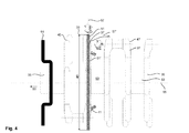
- the crankshaft 35 as in FIG. 4 has a longitudinal extent 59 along the crankshaft axis 55.
- Individual crankshaft cheeks 37 are connected by Kurbelwellenschafte 53 together.
- the crankshaft cheeks 37 each have a surface 47. Selected areas of the surface 47 are equipped with steps 45 or other projections 41. Notwithstanding the longitudinal extension 59 of the crankshaft 35, an axis orientation 57, 57 'is chosen, in which the arrangement of a fuel pump 63 (see FIG. 3 ) is made.
- the crankshaft cheek 37 extends to a circumference 39, which is determined by the diameter 49 of the crankshaft cheek 37.
- On the output shaft 33 of the crankshaft 35 sits, as shown schematically, a driven gear 91.
- a drive plane 51 is determined by the circumference 39 of the crankshaft 37. Individual stages 45 in the surface 47 of the crankshaft 35 can also be used as the drive plane 51 'when a corresponding axis orientation 57' for the fuel pump 63 (according to FIG FIG. 3 ) is selected in contact contact with the crankshaft 35. Individual circumferences 39 on the crankshaft 35 serve as control disks for driving a fuel pump 63 (see FIG. 3 ). In the FIG.
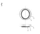
- FIG. 5 shows a crankshaft 35, in which a cam 43 has been incorporated by an oval surface protruding from the crankshaft 35.
- the cam 43 is part of the crankshaft cheek 37.
- the cam 43 is a machined surface 47 part of the crankshaft cheek 37th
- FIG. 6 shows the attachment of a drive member 81 in an axis orientation 57 'at a stage 45 of the crankshaft cheek 37 of the crankshaft 35.
- the crankshaft 35 is held by the crankshaft stalls 27.
- Individual crankshaft cheeks 37 are spaced by crankshaft shafts 53.
- the orientation of the axis orientation 57 ' is in a different direction than the crankshaft axis 55, which coincides with the output shaft 33.
- a good angular direction of the axis orientation 57 ' deviates at an angle of 45 ° from the crankshaft axis 55.
- a drive element 81 (according to FIG. 6 ) is in the design after FIG. 7 attached to the stage 45 of the crankshaft cheek 37 so that a fuel plug 65 passes through an opening 29 - stylized by the openings - in the crankshaft stalls 27 passes.
- the axis orientation 57 is due to the lever 83 from the orientation of the drive member 81 from.
- the crankshaft 35 extends along the crankshaft axis 55 which passes through the crankshaft shafts 53.
- the crankshaft cheek 37 controls a drive element 81 via a surface profile with the aid of a cam 43.
- the drive element 81 directly adjoins the crankshaft cheek 37. Strokes of the drive member 81 are translated via the lever 83 to the Einkolbenhoch horrpumpe 67.
- the lever 83 has a fulcrum that determines the gear ratio of the lever 83.
- fuel pump 65 (after FIG. 7 ) have been designed in the Applicant's company, which require an opening 29 of less than about 2 cm in the crankshaft stalls 27 are in some reciprocating engines 1 (see FIG. 1 ) given such space conditions that a smaller drive element 81, the drive power for the single-piston high-pressure pump 67 must deflect over a lever 83 of the crankshaft cheek 37.
- the axis orientation 57 can additionally be adapted, so that the orientation of the cam 43 is no longer decisive for the axis orientation 57 of the single-piston high-pressure pump 67.
- the single-piston high-pressure pump 67 can be arranged at a point in the reciprocating piston engine 1, which is located beyond the crankshaft stalls 27 adjoining directly on the crankshaft cheek 37.
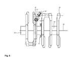
- FIG. 9 shows in cross section to the crankshaft axis 55, a cam control by means of the cam 43 which is smaller than the circumference 39 of the crankshaft 35.
- the drive element 81st superimposed directly on the crankshaft 35, more precisely on the cam-like surface of the crankshaft 35.
- the crankshaft 35 is held by the crankshaft stalls 27.
- the drive element 81 which is advantageously a roller cup ram, is movably mounted on the crankshaft 35, so that a movement along the axis orientation 57 in the drive plane 51 is possible.
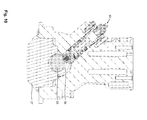
- FIG. 10 shows a similar solution as previously in the FIGS. 3 to 9 shown, wherein instead of the crankshaft cheek 37, a crankshaft shaft 53 is used as actuating means for the fuel pump 63.
- the fuel pump 63 is seated at an acute angle, deflected from the perpendicular to the crankshaft 35, on the crankshaft 35.
- the crankshaft 35 rests in the crankshaft stalls 27.
- the fuel pump 63 is a reciprocating pump driven by a roller cup ram, which is part of the fuel conditioner.
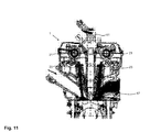
- FIG. 11 shows a reciprocating engine 1, in the cylinder head 17, the gas exchange valves 23 are located.
- the gas exchange valves 23 are controlled by camshafts 21.
- the Kraftstoffauf Schltungsvorraum 61 is arranged so that the combustion chamber 5 can be supplied with a fuel-air mixture.
- FIGS. 1 to 11 can also make an independent inventive contribution.
- the corresponding surface profile in a part of the crankshaft 35 such. B. in the crankshaft cheek 37 or in a crankshaft shaft 53, are incorporated.
- One or more additional machining or assembly steps to produce the control profile for the fuel pump are unnecessary.
Landscapes
- Engineering & Computer Science (AREA)
- Mechanical Engineering (AREA)
- General Engineering & Computer Science (AREA)
- Chemical & Material Sciences (AREA)
- Combustion & Propulsion (AREA)
- Fuel-Injection Apparatus (AREA)
- Shafts, Cranks, Connecting Bars, And Related Bearings (AREA)
Applications Claiming Priority (1)
| Application Number | Priority Date | Filing Date | Title |
|---|---|---|---|
| DE201010016356 DE102010016356A1 (de) | 2010-04-07 | 2010-04-07 | Verbrennungskraftmaschine mit Kraftstoffpumpe |
Publications (2)
| Publication Number | Publication Date |
|---|---|
| EP2385237A2 true EP2385237A2 (fr) | 2011-11-09 |
| EP2385237A3 EP2385237A3 (fr) | 2014-11-26 |
Family
ID=44169023
Family Applications (1)
| Application Number | Title | Priority Date | Filing Date |
|---|---|---|---|
| EP11161250.3A Withdrawn EP2385237A3 (fr) | 2010-04-07 | 2011-04-06 | Moteur à combustion interne doté d'une pompe à carburant |
Country Status (2)
| Country | Link |
|---|---|
| EP (1) | EP2385237A3 (fr) |
| DE (1) | DE102010016356A1 (fr) |
Cited By (3)
| Publication number | Priority date | Publication date | Assignee | Title |
|---|---|---|---|---|
| WO2015113705A1 (fr) * | 2014-01-31 | 2015-08-06 | Bayerische Motoren Werke Aktiengesellschaft | Système d'entraînement d'une pompe à carburant haute pression, ensemble pompe à carburant haute pression et moteur à combustion interne |
| EP3054145A1 (fr) * | 2015-02-05 | 2016-08-10 | Renault S.A.S. | Pompe d'injection de carburant entraînée en mouvement par le vilebrequin du moteur thermique alimenté par la pompe |
| GB2540584A (en) * | 2015-07-22 | 2017-01-25 | Gm Global Tech Operations Llc | Internal combustion engine comprising a fuel unit pump actuated by the crankshaft |
Families Citing this family (1)
| Publication number | Priority date | Publication date | Assignee | Title |
|---|---|---|---|---|
| DE102014223597B4 (de) * | 2014-10-08 | 2019-02-07 | Continental Automotive Gmbh | Rolle für einen Rollenstößel einer Kraftstoffhochdruckpumpe, Rollenstößel, Kraftstoffhochdruckpumpe und Brennkraftmaschine |
Citations (15)
| Publication number | Priority date | Publication date | Assignee | Title |
|---|---|---|---|---|
| GB361641A (en) | 1929-12-20 | 1931-11-26 | Maschf Augsburg Nuernberg Ag | Improvements in or relating to means for driving the fuel pumps of internal combustion engines |
| US3106168A (en) | 1959-09-17 | 1963-10-08 | Gen Motors Corp | Fuel pump drive |
| JPS63109243A (ja) | 1986-10-28 | 1988-05-13 | Mitsubishi Heavy Ind Ltd | 内燃機関のタイミング管制装置 |
| JPS63277853A (ja) | 1987-05-11 | 1988-11-15 | Mitsubishi Heavy Ind Ltd | 内燃機関の燃料噴射ポンプ |
| JPH0242170A (ja) | 1988-08-01 | 1990-02-13 | Honda Motor Co Ltd | エンジンにおける燃料ポンプ取付構造 |
| JPH02301660A (ja) | 1989-05-17 | 1990-12-13 | Yamaha Motor Co Ltd | 内燃エンジンにおける燃料ポンプの駆動機構 |
| DE4029428A1 (de) | 1989-09-27 | 1991-04-04 | Volkswagen Ag | Brennkraftmaschine mit einer von ihrer kurbelwelle her angetriebenen oelpumpe |
| EP0590362A1 (fr) | 1992-09-29 | 1994-04-06 | Steyr Nutzfahrzeuge Ag | Agencement de came d'entraînement pour entrainer le piston d'une pompe d'injection pour un moteur à combustion interne |
| DE102006006823B3 (de) | 2006-02-14 | 2007-03-15 | Siemens Ag | Verfahren und Vorrichtung zum Einspritzen von Kraftstoff |
| JP2008038848A (ja) | 2006-08-09 | 2008-02-21 | Yanmar Co Ltd | 燃料噴射ポンプ |
| DE102007056418A1 (de) | 2007-11-23 | 2009-06-04 | Continental Automotive Gmbh | Einspritzanlage für eine Brennkraftmaschine |
| DE102008007025A1 (de) | 2008-01-31 | 2009-08-06 | Continental Automotive Gmbh | Pumpe zur Förderung eines Fluids |
| DE102008008438A1 (de) | 2008-02-11 | 2009-08-13 | Continental Automotive Gmbh | Hochdruckpumpe |
| DE102008000711A1 (de) | 2008-03-17 | 2009-09-24 | Robert Bosch Gmbh | Hochdruckpumpe |
| DE102008002178A1 (de) | 2008-06-03 | 2009-12-10 | Robert Bosch Gmbh | Hochdruckpumpe |
Family Cites Families (4)
| Publication number | Priority date | Publication date | Assignee | Title |
|---|---|---|---|---|
| DE620606C (de) * | 1934-02-08 | 1935-10-24 | Humboldt Deutzmotoren Akt Ges | Brennstoffeinspritzpumpen von Sternmotoren |
| DE102004054937B4 (de) * | 2004-11-13 | 2009-04-02 | Audi Ag | Brennkraftmaschine mit Ölpumpe |
| JP4592633B2 (ja) * | 2006-03-31 | 2010-12-01 | 本田技研工業株式会社 | 内燃機関の燃料ポンプ |
| DE202008007354U1 (de) * | 2008-05-31 | 2008-08-07 | Stöhr, René, Dipl.-Ing. | Kraftstoffeinspritzpumpe für Verbrennungsmotoren |
-
2010
- 2010-04-07 DE DE201010016356 patent/DE102010016356A1/de not_active Withdrawn
-
2011
- 2011-04-06 EP EP11161250.3A patent/EP2385237A3/fr not_active Withdrawn
Patent Citations (15)
| Publication number | Priority date | Publication date | Assignee | Title |
|---|---|---|---|---|
| GB361641A (en) | 1929-12-20 | 1931-11-26 | Maschf Augsburg Nuernberg Ag | Improvements in or relating to means for driving the fuel pumps of internal combustion engines |
| US3106168A (en) | 1959-09-17 | 1963-10-08 | Gen Motors Corp | Fuel pump drive |
| JPS63109243A (ja) | 1986-10-28 | 1988-05-13 | Mitsubishi Heavy Ind Ltd | 内燃機関のタイミング管制装置 |
| JPS63277853A (ja) | 1987-05-11 | 1988-11-15 | Mitsubishi Heavy Ind Ltd | 内燃機関の燃料噴射ポンプ |
| JPH0242170A (ja) | 1988-08-01 | 1990-02-13 | Honda Motor Co Ltd | エンジンにおける燃料ポンプ取付構造 |
| JPH02301660A (ja) | 1989-05-17 | 1990-12-13 | Yamaha Motor Co Ltd | 内燃エンジンにおける燃料ポンプの駆動機構 |
| DE4029428A1 (de) | 1989-09-27 | 1991-04-04 | Volkswagen Ag | Brennkraftmaschine mit einer von ihrer kurbelwelle her angetriebenen oelpumpe |
| EP0590362A1 (fr) | 1992-09-29 | 1994-04-06 | Steyr Nutzfahrzeuge Ag | Agencement de came d'entraînement pour entrainer le piston d'une pompe d'injection pour un moteur à combustion interne |
| DE102006006823B3 (de) | 2006-02-14 | 2007-03-15 | Siemens Ag | Verfahren und Vorrichtung zum Einspritzen von Kraftstoff |
| JP2008038848A (ja) | 2006-08-09 | 2008-02-21 | Yanmar Co Ltd | 燃料噴射ポンプ |
| DE102007056418A1 (de) | 2007-11-23 | 2009-06-04 | Continental Automotive Gmbh | Einspritzanlage für eine Brennkraftmaschine |
| DE102008007025A1 (de) | 2008-01-31 | 2009-08-06 | Continental Automotive Gmbh | Pumpe zur Förderung eines Fluids |
| DE102008008438A1 (de) | 2008-02-11 | 2009-08-13 | Continental Automotive Gmbh | Hochdruckpumpe |
| DE102008000711A1 (de) | 2008-03-17 | 2009-09-24 | Robert Bosch Gmbh | Hochdruckpumpe |
| DE102008002178A1 (de) | 2008-06-03 | 2009-12-10 | Robert Bosch Gmbh | Hochdruckpumpe |
Cited By (5)
| Publication number | Priority date | Publication date | Assignee | Title |
|---|---|---|---|---|
| WO2015113705A1 (fr) * | 2014-01-31 | 2015-08-06 | Bayerische Motoren Werke Aktiengesellschaft | Système d'entraînement d'une pompe à carburant haute pression, ensemble pompe à carburant haute pression et moteur à combustion interne |
| CN105765212A (zh) * | 2014-01-31 | 2016-07-13 | 宝马股份公司 | 燃料高压泵的驱动系统、燃料高压泵组件以及内燃机 |
| EP3054145A1 (fr) * | 2015-02-05 | 2016-08-10 | Renault S.A.S. | Pompe d'injection de carburant entraînée en mouvement par le vilebrequin du moteur thermique alimenté par la pompe |
| FR3032488A1 (fr) * | 2015-02-05 | 2016-08-12 | Renault Sa | Pompe d'injection de carburant entrainee en mouvement par le vilebrequin du moteur thermique alimente par la pompe |
| GB2540584A (en) * | 2015-07-22 | 2017-01-25 | Gm Global Tech Operations Llc | Internal combustion engine comprising a fuel unit pump actuated by the crankshaft |
Also Published As
| Publication number | Publication date |
|---|---|
| EP2385237A3 (fr) | 2014-11-26 |
| DE102010016356A1 (de) | 2011-10-13 |
Similar Documents
| Publication | Publication Date | Title |
|---|---|---|
| DE102008014080B4 (de) | Variabler Ventiltrieb für einen Verbrennungsmotor | |
| EP1521914B1 (fr) | Unite de pompe a pistons radiaux | |
| EP2375030A2 (fr) | Moteur à combustion interne doté d'une pompe à carburant | |
| DE102013223746B3 (de) | Vorrichtung zur Veränderung des Verdichtungsverhältnisses einer Zylindereinheit einer Hubkolbenbrennkraftmaschine | |
| EP2385237A2 (fr) | Moteur à combustion interne doté d'une pompe à carburant | |
| EP2906803A1 (fr) | Procédé et dispositif permettant de faire fonctionner un moteur à combustion interne | |
| DE102015013489A1 (de) | Brennkraftmaschine mit Doppelkurbeltrieb und variabler Verdichtung | |
| DE60117980T2 (de) | Fremdgezündete rotierende brennkraftmaschine | |
| EP2088310A1 (fr) | Moteur à combustion interne doté d'un système d'injection Common-Rail | |
| DE1403909A1 (de) | Zahnradpumpe | |
| DE102015105735B4 (de) | Verfahren zum Betreiben einer Kraftstoffpumpe für einen Verbrennungsmotor, Kraftstoffpumpe und Verbrennungsmotor | |
| DE102017207644A1 (de) | Verfahren zum Verändern eines zylinderzugehörigen Verdichtungsverhältnisses e einer fremdgezündeten Brennkraftmaschine und Brennkraftmaschine zur Durchführung eines derartigen Verfahrens | |
| DE69400367T2 (de) | Brennkraftmaschine | |
| DE102015210597A1 (de) | Hubkolbenmotor und Kraftfahrzeug | |
| DE102018006666B4 (de) | Verbrennungskraftmaschine für einen Kraftwagen, mit einer Steuereinheit zum Ausrichten einer Nockenwelle und Verfahren zum Betreiben einer solchen Verbrennungskraftmaschine | |
| EP3364010B1 (fr) | Bielle pour un moteur à combustion interne à compression variable | |
| DE102008006137B4 (de) | Taumelgetriebe und Taumelgetriebesystem | |
| DE102004003910B4 (de) | Selbstzündende Zweitakt-Brennkraftmaschine mit großem Hub-Bohrungsverhältnis | |
| DE102016217983A1 (de) | Umschaltelement zur Steuerung einer Verstellvorrichtung für eine Änderung des Verdichtungsverhältnisses einer Zylindereinheit einer Hubkolbenbrennkraftmaschine | |
| DE102023104487B3 (de) | Verfahren einer Verbrennungskraftmaschine mit zwei mal drei Takten | |
| DE102012019176A1 (de) | Kolbenbrennkraftmaschine mit einem variablen Verdichtungsbehältnis | |
| DE102004014518B4 (de) | Druckluftbetriebener Kolbenmotor sowie ein Ventil, welches einen Ventilkörper mit einem Ventilkopf, einen Ventilschaft und einen Ventilfuß aufweist | |
| DE69917632T2 (de) | Rotierende Brennkraftmaschine | |
| DE102012221765A1 (de) | Pumpe, insbesondere Kraftstoffhochdruckpumpe für eine Kraftstoffeinspritzeinrichtung | |
| DE2824671A1 (de) | Mehrzylindrige hubkolbenmaschine, insbesondere brennkraftmaschine |
Legal Events
| Date | Code | Title | Description |
|---|---|---|---|
| AK | Designated contracting states |
Kind code of ref document: A2 Designated state(s): AL AT BE BG CH CY CZ DE DK EE ES FI FR GB GR HR HU IE IS IT LI LT LU LV MC MK MT NL NO PL PT RO RS SE SI SK SM TR |
|
| AX | Request for extension of the european patent |
Extension state: BA ME |
|
| PUAI | Public reference made under article 153(3) epc to a published international application that has entered the european phase |
Free format text: ORIGINAL CODE: 0009012 |
|
| PUAL | Search report despatched |
Free format text: ORIGINAL CODE: 0009013 |
|
| AK | Designated contracting states |
Kind code of ref document: A3 Designated state(s): AL AT BE BG CH CY CZ DE DK EE ES FI FR GB GR HR HU IE IS IT LI LT LU LV MC MK MT NL NO PL PT RO RS SE SI SK SM TR |
|
| AX | Request for extension of the european patent |
Extension state: BA ME |
|
| RIC1 | Information provided on ipc code assigned before grant |
Ipc: F04B 17/05 20060101ALI20141022BHEP Ipc: F02M 59/10 20060101ALI20141022BHEP Ipc: F02M 39/02 20060101AFI20141022BHEP Ipc: F04B 53/00 20060101ALI20141022BHEP Ipc: F02M 59/02 20060101ALI20141022BHEP |
|
| STAA | Information on the status of an ep patent application or granted ep patent |
Free format text: STATUS: THE APPLICATION IS DEEMED TO BE WITHDRAWN |
|
| 18D | Application deemed to be withdrawn |
Effective date: 20141101 |