EP2385264A2 - Kupplungsbaugruppe mit Verschleißausgleich - Google Patents
Kupplungsbaugruppe mit Verschleißausgleich Download PDFInfo
- Publication number
- EP2385264A2 EP2385264A2 EP11160936A EP11160936A EP2385264A2 EP 2385264 A2 EP2385264 A2 EP 2385264A2 EP 11160936 A EP11160936 A EP 11160936A EP 11160936 A EP11160936 A EP 11160936A EP 2385264 A2 EP2385264 A2 EP 2385264A2
- Authority
- EP
- European Patent Office
- Prior art keywords
- spring
- coupling assembly
- axial
- spring element
- retaining
- Prior art date
- Legal status (The legal status is an assumption and is not a legal conclusion. Google has not performed a legal analysis and makes no representation as to the accuracy of the status listed.)
- Granted
Links
Images


Classifications
-
- F—MECHANICAL ENGINEERING; LIGHTING; HEATING; WEAPONS; BLASTING
- F16—ENGINEERING ELEMENTS AND UNITS; GENERAL MEASURES FOR PRODUCING AND MAINTAINING EFFECTIVE FUNCTIONING OF MACHINES OR INSTALLATIONS; THERMAL INSULATION IN GENERAL
- F16D—COUPLINGS FOR TRANSMITTING ROTATION; CLUTCHES; BRAKES
- F16D13/00—Friction clutches
- F16D13/58—Details
- F16D13/583—Diaphragm-springs, e.g. Belleville
- F16D13/585—Arrangements or details relating to the mounting or support of the diaphragm on the clutch on the clutch cover or the pressure plate
Definitions
- the present invention relates to a clutch assembly, in particular for a friction clutch of a motor vehicle, having at least one clutch housing in which a pressure acting on a diaphragm plate spring is arranged, which is fixed to the clutch housing by means of a retaining ring with circumferentially distributed axially projecting from the retaining ring retaining tabs, wherein the retaining tabs are designed to define an axial stop, and wherein between two adjacent components of the coupling assembly, which are arranged between the retaining ring and the axial stop of the retaining tabs, a spring element is arranged, which exerts an axial spring force on the adjacent components.
- a coupling device in which between the holding elements and the coupling housing or between the holding elements and the diaphragm spring, an annular spring element is used, which has axially offset portions, which exerts an axial force on the surrounding components.
- the present invention is therefore an object of the invention to provide a wear-compensating clutch assembly for a friction clutch, which is inexpensive to manufacture and easy to assemble and has a sufficiently large travel.
- the invention is based on the idea to use instead of a circumferentially inserted spring ring individual resilient elements whose number ultimately determines the total spring force.
- the spring elements are arranged in each case on at least one of the retaining tabs of a retaining ring which defines the diaphragm spring on a coupling housing.
- the spring elements are inserted between two adjacent components of the coupling assembly such that they are arranged between the retaining ring and the axial stop of the retaining tabs.
- the axial stop of the retaining tabs can be done for example in the previously known manner by means of bending the tab ends in the direction of the coupling housing.
- each individual spring element has at least two edge-side support regions which rest at least partially against the one component and furthermore has at least one axial elevation arranged between the support regions, which abuts at least partially against the other component.
- the spring element between the axial stop of the retaining tabs and the clutch housing can be arranged, wherein the axial elevation is supported on the axial stop of the retaining tab, while the two edge-side support portions bear against the coupling housing.
- the axial elevation is compressed, so that a spring bias in the axial direction between the clutch housing and the axial stop of the retaining tabs arises.
- this spring preload causes the coupling housing and the axial stop of the retaining element to be forced apart so that no air gap can arise between the diaphragm spring and the coupling housing or another component.
- the exact configuration of the spring element may vary in order to be adapted to the structural conditions.
- common to all spring elements is that the axial elevation of the spring element is supported on one component and the support regions on the other component.
- the axial elevation has at least one recess for at least one retaining tab.
- the recess may be formed as an opening, in particular as a slot, which is penetrated by the retaining tab. This has the advantage that the centrifugal forces occurring during operation of the clutch do not cause slippage of the spring element.
- the spring element is formed annular-segment-shaped, wherein the radius is advantageously adapted to the radius adjacent component of the coupling.
- the spring element according to the invention on at least one of the peripheral support areas on a guide which is adapted to engage around a retaining tab which is adjacent to the arranged on the axial elevation retaining tab. It is particularly preferred if both edge-side support areas have such a guide. By means of this guide, the installation position of the spring element is defined, and secured against slipping occurring during operation of the clutch centrifugal forces.
- the supporting region is preferably designed such that a relative movement of the supporting region along the associated component is possible. At the same time, this mobility allows the return movement occurring during the expansion of the spring element-shortening-of the support areas not to be impaired.
- the guides are preferably designed so that the spring element can move along the retaining tabs.
- the guide can be designed as a guide open at the edge, so that the guide has a groove shape. This has the particular advantage that when installing the wear compensation device no excessive care to the circumferential Alignment must be placed, since the groove-shaped recess has fault tolerances for installation.
- the guide may also have as an opening, which may be formed in particular as a slot, preferably, wherein the dimensioning is preferably adapted to the expected movement.
- the spring element may have two or more axial elevations, which may each be provided with recesses, wherein between the axial elevations each have a further portion region is arranged.
- the spring element comprises three to five retaining tabs. In this case, preferably two retaining tabs are encompassed by the guides, while the centrally arranged holding tab / s is / are arranged on the axial elevation (s).
- the recess may be formed in the axial elevation as an opening, which is penetrated by a retaining tab.
- the spring element is not arranged between the coupling housing and the axial stop of the retaining tab, but between the diaphragm spring and the retaining ring or between the diaphragm spring and the clutch housing.
- the radial recess preferably extends over the entire axial elevation.
- At least two separate spring elements are present, which in each case has at least two edge-side support areas and an axial elevation arranged between the support areas.
- the spring elements are arranged such that an axial tilting of the components in the clutch housing is avoidable. That means, that the spring elements are arranged distributed substantially equidistant from one another over the circumference. For example, if two spring elements are provided, they are arranged opposite one another. If three spring elements are provided, these also have a substantially equal distance from one another.
- the spring force of the spring elements on the height of the axial elevation and the stiffness of the inserted spring element material can be determined.
- the spring force can also be adjusted by the number of existing spring elements. The rule is that the spring force increases when more spring elements are present. This has the particular advantage that depending on the requirements of the clutch to be manufactured, the spring characteristic of the spring element can be easily and inexpensively adjusted.
- FIG. 1 shows a schematic plan view of a portion of a friction clutch 1 with a clutch housing 2, which comprises a diaphragm spring 4.
- the diaphragm spring 4 and the clutch housing 2 are fixed to each other by means of a retaining ring 5.
- a retaining ring 5 Of the retaining ring 5, however, are in Fig. 1 only the circumferentially distributed axially projecting retaining tabs 6 visible.
- the retaining tabs 6 are bent radially outwards, so that they form an axial stop 8. Instead of the tab ends bent over axially outward, the retaining tabs 6 can also be bent over radially inwards or circumferentially in the clockwise or counterclockwise direction in order to define the axial stop 8.
- the retaining tabs 6 are guided during assembly through openings (not shown) in the diaphragm spring 4 and openings 10 in the clutch housing 2 and then fixed, so that the diaphragm spring is fixed to the coupling housing.
- FIG. 1 and the in Fig. 2 shown detailed view of the spring element 12 is shown, between the clutch housing 2 and the axial stops 8a to 8c of three adjacent retaining tabs 6a to 6c a spring element 12 is arranged, which is designed according to the invention to compensate for wear.
- the spring element 12 spans three retaining elements 6a, 6b, 6c, wherein the retaining elements 6a and 6c are encompassed by peripheral guides 14, 15, while the retaining element 6b passes through the centrally arranged recess 16.
- the peripheral guides are arranged in support areas 18, 20, while the opening 16 is formed in an axial elevation 22.
- This survey 22 is pressed during assembly when bending the retaining tabs 6 in the direction of the clutch housing 2, so that the spring preload arises.
- the spring element 12 can also encompass four or more retaining tabs 6. However, it is also possible that the spring element 12 is arranged only on one of the retaining tabs 6 and does not extend to the adjacent retaining tabs. If such spring elements are to be attached to each holding lug, preferably the supporting regions 18, 20 are dimensioned such that they do not block each other during movement of the spring elements.
- the spring element 12 further has an approximately centrally disposed opening 16 which is penetrated by a retaining tab 6b.
- the retaining tab 6b is arranged on the axial elevation 22 of the spring element 12.
- the axial elevation 22 bears against the axial stop 8b of the retaining tab 6b, while the support areas 18, 20 are supported on the coupling housing 2.
- the axial elevation 22 rests against the clutch housing 2, while the support areas 18, 20 are supported on the axial stops 8a and 8c.
- the edge-side guides 14, 15 may, as shown here, be open at the edge, so that they have a groove shape. This embodiment has the advantage that in the assembly of the spring element 12, even in circumferentially inaccurate positioning of the spring element 12, a mobility of the retaining tabs 6a, 6c in the guides 14, 15 is possible.
- the spring element 12 has an axial elevation 22, which in the embodiment illustrated here has the opening 16 for receiving the retaining tab 6b.
- the opening 16 is preferably formed as a slot, which is dimensioned according to the dimensions of the retaining tab 6b.
- the height of the axial elevation 22, the stiffness of the material of the spring element 12 and the number of circumferentially distributed over the coupling spring elements 12 determine the total spring force that applies the spring element.
- the spring preload is caused by the compression or reduction of the axial elevation 22 when bending the retaining tabs 6.
- the spring element 12 is pushed apart in the direction of the arrows 24, 26, so that a tangential to the axial elevation 22 aligned relative movement between the support areas 18, 20th and the holding tabs 6a, 6c accommodated in the guides 14, 15 are formed. If wear occurs, play arises between retaining ring 5, diaphragm spring 4 and housing 2, so that the spring element 12 begins to relax and contracts again, so that in turn a relative movement of the retaining elements 6a, 6c in the guides 14, 15 is formed. For this reason, the guides 14, 15 are preferably dimensioned such that a mobility of the retaining tabs 6a, 6c is ensured.
- FIG. 3 shows a sectional view through the in FIG. 1 shown friction clutch along the line I.
- the spring element 12 is located between the clutch cover housing 2 and the axial stop 8 of the retaining tabs 6, while the retaining ring 5 rests against the diaphragm spring 4.
- FIG. 4 also shows a sectional view through the in FIG. 1 shown friction clutch, along the line II.
- the axial projection 22 may be formed such that it is supported on the axial stop 8 of the retaining tab 6, while the support portions 18, 20 abut the clutch housing 2.
- the spring element 12 may also be arranged between the retaining ring 5 and the diaphragm spring 4 or between the diaphragm spring 4 and housing 2. Both position options are in FIG. 4 marked with A or B respectively. Depending on the installation position, it is advantageous to adjust the axial elevation 22 and the support areas 18, 20 to the structural conditions.
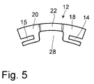
- the recess in the axial elevation 22 is not formed as an opening 16 but as a recess 28.
- the spring element 12 guides 14 and 15, which surround the retaining tabs 6 and provide a support to the diaphragm spring 4.
- the axial elevation 22 is supported on the retaining ring 5, so that again when worn the Game between diaphragm spring 4 and the surrounding components is balanced.
- the spring element 12 may also comprise two or more axial protrusions 22, each with a further support region arranged therebetween, so that four or more retaining tabs can be encompassed instead of the three gripped retaining tabs.
- a retaining tab 6 of the retaining ring 5 is pushed and bent by the middle recesses during assembly.
- the axial elevations 22 of the spring element 12 are compressed, so that a spring preload arises.
Landscapes
- Engineering & Computer Science (AREA)
- General Engineering & Computer Science (AREA)
- Mechanical Engineering (AREA)
- Mechanical Operated Clutches (AREA)
Abstract
Description
- Vorliegende Erfindung betrifft eine Kupplungsbaugruppe, insbesondere für eine Reibungskupplung eines Kraftfahrzeugs, mit zumindest einem Kupplungsgehäuse, in dem eine auf eine Druckplatte wirkende Membranfeder angeordnet ist, die am Kupplungsgehäuse mittels eines Halterings mit umfänglich verteilten axial vom Haltering abstehenden Haltelaschen festgelegt ist, wobei die Haltelaschen dazu ausgelegt sind, einen axialen Anschlag zu definieren, und wobei zwischen zwei benachbarten Bauteilen der Kupplungsbaugruppe, die zwischen dem Haltering und dem axialen Anschlag der Haltelaschen angeordnet sind, ein Federelement angeordnet ist, das eine axiale Federkraft auf die benachbarten Bauteile ausübt.
- Bei durch Druck betätigten Druckplatten insbesondere von Kraftfahrzeug-Reibungskupplungen stellt sich bei Vorrichtungen der oben genannten Art über die Gebrauchsdauer der Kupplung ein Verschleiß der Membranfederauflagen ein. Durch diesen Verschleiß wird der Abhub der Druckplatte verringert. Wird der zu erwartende Verschleiß bei der Auslegung der Kupplung vorgehalten, ist der Abhub der neuen Kupplung um den Verschleiß grösser als eigentlich benötigt. Dadurch ergibt sich eine ungünstige Übersetzung und ein schlechter Wirkungsgrad mit entsprechend großer Ausrückkraft.
- Wird dagegen der Verschleiß nicht berücksichtigt, reduziert die durch den Verschleiß entstehende Luft zwischen der Membranfeder und den umgebenden Bauteilen den Abhub der Druckplatte. Eine Folge des reduzierten Abhubs kann eine Fehlfunktion der Druckplatte sein, d.h. die Kupplung kann nicht mehr getrennt werden. Dies bedeutet aber gleichzeitig, dass ein Gangwechsel nicht mehr möglich ist, so dass das Kraftfahrzeug unter Umständen abgeschleppt werden muss.
- Es ist deshalb im Stand der Technik vorgeschlagen worden, den Auflagenverschleiß durch vorgespannte elastische Elemente in Form einer Ringfeder mit axialen Erhebungen oder einer Tellerfeder auszugleichen. Bei Druckplatten mit Haltering wird diese Tellerfeder oberhalb des Gehäuses unter die Laschen des Halterings eingelegt, so dass bei der Montage die Feder vorgespannt wird. Kommt es zu einem Verschleiß, entspannt sich die Tellerfeder um einen entsprechenden Betrag und gleicht so den Verschleiß aus.
- In der
DE 102007053724 und derDE 102007053161 wird eine Kupplungsvorrichtung vorgeschlagen, bei der zwischen dem Halteelemente und dem Kupplungsgehäuse oder zwischen dem Haltelemente und der Membranfeder ein ringförmiges Federelement eingesetzt ist, das axial zueinander versetzte Abschnitte aufweist, die eine axiale Kraft auf die umgebende Bauteile ausübt. - Zudem ist aus der
GB 1 511 745 - Nachteilig an diesen Lösungen ist jedoch, dass die Herstellung der Federn sehr aufwändig ist, insbesondere wenn dafür Sorge getragen werden soll, dass sie in der genau gewünschten Umfangslage zu liegen kommen. Auch die Montagekosten sind relativ hoch, da die gefertigten Federn bei der Montage präzise gehandhabt werden müssen, um in die richtige Montageendlage zu gelangen. Darüber hinaus ist der von den Ringfedern bereitgestellte Federweg meist zu gering.
- Der vorliegenden Erfindung liegt daher die Aufgabe zugrunde, eine verschleißausgleichende Kupplungsbaugruppe für eine Reibungskupplung bereitzustellen, die kostengünstig zu fertigen und leicht zu montieren ist und einen ausreichend großen Federweg aufweist.
- Diese Aufgabe wird gelöst durch eine Kupplungsbaugruppe gemäß Patentanspruch 1.
- Der Erfindung liegt die Idee zugrunde, statt eines umfänglich eingesetzten Federrings einzelne federnde Elemente einzusetzen, deren Anzahl letztendlich die Gesamtfederkraft bestimmt. Die Federelemente werden jeweils an mindestens einer der Haltelaschen eines die Membranfeder an einem Kupplungsgehäuse festlegenden Halterings angeordnet. Dabei werden die Federelemente derart zwischen zwei benachbarten Bauteilen der Kupplungsbaugruppe eingesetzt, dass sie zwischen dem Haltering und dem axialen Anschlag der Haltelaschen angeordnet sind. Der axiale Anschlag der Haltelaschen kann beispielsweise in vorbekannter Weise mittels Umbiegens der Laschenenden in Richtung Kupplungsgehäuse erfolgen.
- Zudem weist jedes einzelne Federelement mindestens zwei randseitige Abstützbereiche auf, die zumindest teilweise an dem einem Bauteil anliegen und weist weiterhin mindestens eine zwischen den Abstützbereichen angeordnete axiale Erhebung auf, die zumindest teilweise an dem anderen Bauteil anliegt.
- Das bedeutet beispielsweise, dass das Federelement zwischen dem axialen Anschlag der Haltelaschen und dem Kupplungsgehäuse angeordnet sein kann, wobei sich die axiale Erhebung an dem axialen Anschlag der Haltelasche abstützt, während die beiden randseitigen Abstützbereiche an dem Kupplungsgehäuse anliegen. Bei der Montage wird die axiale Erhebung zusammengedrückt, so dass eine Federvorspannung in axialer Richtung zwischen dem Kupplungsgehäuse und dem axialen Anschlag der Haltelaschen entsteht. Bei Verschleiß bewirkt diese Federvorspannung, dass Kupplungsgehäuse und axialer Anschlag des Halteelements auseinandergedrückt werden, so dass zwischen Membranfeder und Kupplungsgehäuse oder einem anderen Bauteil kein Luftspalt entstehen kann.
- Dabei ist es egal, ob das Federelement zwischen dem axialen Anschlag der Haltelaschen und dem Kupplungsgehäuse oder zwischen dem Haltering und der Membranfeder oder zwischen dem Kupplungsgehäuse und der Membranfeder angeordnet ist. Es kann aber auch allgemein zwischen zwei anderen Bauteilen, die zwischen dem axialen Anschlag der Haltelaschen und dem Haltering angeordnet sind, vorhanden sein, da lediglich sichergestellt werden sollte, dass kein Luftspalt zwischen der Membranfeder und einem der sie umgebenden Bauteilen entsteht.
- Abhängig von der Einbaulage kann die genaue Ausgestaltung des Federelements variieren, um an die baulichen Gegebenheiten angepasst zu werden. Gemein ist allen Federelementen jedoch, dass sich die axiale Erhebung des Federelements an dem einen Bauteil und die Abstützbereiche an dem anderen Bauteil abstützen.
- Gemäß einer bevorzugen Ausführungsform der Erfindung, weist die axiale Erhebung mindestens eine Aussparung für mindestens eine Haltelasche auf. Dadurch kann das Federelement leicht und selbsterklärend positioniert werden, wodurch Montagefehler vermeidbar sind.
- Zudem kann die Aussparung als Öffnung, insbesondere als Langloch ausgebildet sein, die von der Haltelasche durchsetzt wird. Dies hat den Vorteil, dass die beim Betrieb der Kupplung auftretenden Fliehkräfte kein Verrutschen des Federelements bewirken.
- Um ein gutes Einpassen des Federelements in die Kupplung zu erreichen, ist zudem vorteilhaft, wenn das Federelement kreisringabschnittsförmig ausgebildet ist, wobei der Radius vorteilhafterweise an dem Radius benachbarten Bauteils der Kupplung angepasst ist.
- Gemäß einem weiteren bevorzugten Ausführungsbeispiel weist das erfindungsgemäße Federelement an mindestens einem der randseitigen Abstützbereiche eine Führung auf, die dazu ausgelegt ist, eine Haltelasche, die der an der axialen Erhebung angeordneten Haltelasche benachbart ist, zu umgreifen. Dabei ist besonders bevorzugt, wenn beide randseitigen Abstützbereiche eine derartige Führung aufweisen. Mittels dieser Führung ist die Einbaulage des Federelements definiert, und bei den beim Betrieb der Kupplung auftretenden Fliehkräften gegen ein Verrutschen gesichert.
- Da das Bereitstellen der Federvorspannung durch Niederdrücken der axialen Erhebung auch eine tangentiale Bewegung, sprich eine Verlängerung, des Federelements bewirkt, ist der Abstützbereich vorzugsweise derart gestaltet, dass eine Relativbewegung des Abstützbereichs entlang des zugehörigen Bauteils möglich ist. Gleichzeitig ermöglicht diese Beweglichkeit, dass die beim Entspannen des Federelements auftretende Rückbewegung - Verkürzung - der Abstützbereiche nicht beeinträchtig wird.
- Dabei sind vorzugsweise die die Führungen dazu ausgelegt, dass sich das Federelement entlang der Haltelaschen bewegen kann.
- Um eine derartige Beweglichkeit bereitzustellen, kann die Führung als randseitig offene Führung ausgebildet, so dass die Führung eine Nutform aufweist. Dies hat insbesondere den Vorteil, dass beim Einbau der Verschleißausgleichsvorrichtung keine übermäßige Sorgfalt an die umfängliche Ausrichtung gelegt werden muss, da die nutförmige Aussparung Fehlertoleranzen für den Einbau aufweist.
- Statt der Nutform kann die Führung jedoch auch als Öffnung, die insbesondere als Langloch ausgebildet sein kann, aufweisen, wobei vorzugsweise die Dimensionierung an die zu erwartende Bewegung angepasst ist.
- Gemäß einem weiteren vorteilhaften Ausführungsbeispiel kann das Federelement zwei oder mehr axiale Erhebungen aufweisen, die jeweils mit Aussparungen ausgestattet sein können, wobei zwischen den axialen Erhebungen jeweils ein weiterer Abschnittsbereich angeordnet ist. Vorteilhafterweise umfasst das Federelement drei bis fünf Haltelaschen. Dabei werden vorzugsweise zwei Haltelaschen von den Führungen umfasst, während die mittig angeordnete/n Haltelasche/n an der/n axialen Erhebung/en angeordnet ist/sind.
- Wie bereits oben erwähnt, kann die Aussparung in der axialen Erhebung als Öffnung ausgebildet sein, die von einer Haltelasche durchsetzt ist. Es ist jedoch auch möglich, die Aussparung als radiale Einbuchtung auszubilden, so dass die Haltelasche in der Einbuchtung zu liegen kommt. Diese Ausführungsform ist insbesondere dann von Vorteil, wenn das Federelement nicht zwischen dem Kupplungsgehäuse und dem axialem Anschlag der Haltelasche angeordnet ist, sondern zwischen der Membranfeder und dem Haltering bzw. zwischen der Membranfeder und dem Kupplungsgehäuse. Dabei erstreckt sich die radiale Einbuchtung vorzugsweise über die gesamte axiale Erhebung.
- Gemäß einem weiteren bevorzugten Ausführungsbeispiel sind mindestens zwei separate Federelemente vorhanden, die jeweils mindestens zwei randseitige Abstützbereiche und eine zwischen den Abstützbereichen angeordnet axiale Erhebung aufweist. Dabei sind die Federelemente derart angeordnet, dass ein axiales Kippen der Bauteile im Kupplungsgehäuse vermeidbar ist. Das bedeutet, dass die Federelemente im Wesentlichen äquidistant zueinander über den Umfang verteilt angeordnet werden. Sind beispielsweise zwei Federelemente vorgesehen, werden diese einander gegenüberliegend angeordnet. Sind drei Federelemente vorgesehen, so weisen auch diese einen im Wesentlichen gleichen Abstand zueinander auf.
- Vorzugsweise kann die Federkraft der Federelemente über die Höhe der axialen Erhebung und die Steifheit des eingesetzten Federelementmaterials bestimmt werden. Die Federkraft kann aber auch über die Anzahl der vorhandenen Federelemente eingestellt werden. Dabei gilt, dass sich die Federkraft erhöht, wenn mehr Federelemente vorhanden sind. Dies hat insbesondere den Vorteil, dass je nach Anforderung an die zu fertigende Kupplung die Federkennlinie des Federelements einfach und kostengünstig angepasst werden kann.
- Weitere Vorteile und bevorzugte Ausführungsformen sind in den Unteransprüchen, der Beschreibung und den Zeichnungen definiert.
- Die Erfindung ist nachfolgend beispielhaft ohne Beschränkung der Allgemeinheit anhand von in den Zeichnungen dargestellten Ausführungsbeispielen näher erläutert.
- Es zeigen:
-
Figur 1 : eine schematische Aufsicht auf einen Ausschnitt einer Reibungskupplung gemäß einem ersten Ausführungsbeispiel vorliegender Erfindung; -
Figur 2 : eine schematische Aufsicht auf ein erstes Ausführungsbeispiel des erfindungsgemäßen Federelements; -
Figur 3 : eine schematische Schnittansicht durch die inFigur 1 dargestellte Reibungskupplung entlang der Schnittlinie I; -
Figur 4 : eine schematische Schnittansicht durch die inFigur 1 dargestellte Reibungskupplung entlang der Schnittlinie II; und -
Figur 5 : eine schematische Aufsicht auf ein zweites Ausführungsbeispiel des erfindungsgemäßen Federelements. - Im Folgenden werden gleichartige oder gleichwirkende Elemente mit den gleichen Bezugszeichen bezeichnet.
-
Figur 1 zeigt eine schematische Aufsicht auf einen Teil einer Reibungskupplung 1 mit einem Kupplungsgehäuse 2, das eine Membranfeder 4 umfasst. Die Membranfeder 4 und das Kupplungsgehäuse 2 sind mittels eines Halterings 5 aneinander festgelegt. Von dem Haltering 5 sind allerdings inFig. 1 nur die umfänglich verteilten axial abstehenden Haltelaschen 6 sichtbar. Die Haltelaschen 6 sind radial nach außen umgebogen, so dass sie einen axialen Anschlag 8 ausbilden. Statt der axial nach außen umgebogenen Laschenenden, können die Haltelaschen 6 auch radial nach innen oder umfänglich im oder gegen den Uhrzeigersinn umgebogen werden, um den axialen Anschlag 8 zu definieren. - Die Haltelaschen 6 werden bei der Montage durch Öffnungen (nicht dargestellt) in der Membranfeder 4 und Öffnungen 10 in dem Kupplungsgehäuse 2 geführt und dann fixiert, so dass die Membranfeder an dem Kupplungsgehäuse festgelegt ist.
- Wie
Figur 1 und der inFig. 2 dargestellten detaillierten Ansicht des Federelements 12 zu entnehmen ist, ist zwischen dem Kupplungsgehäuse 2 und den axialen Anschlägen 8a bis 8c dreier nebeneinander liegender Haltelaschen 6a bis 6c ein Federelement 12 angeordnet, das erfindungsgemäß dazu ausgelegt ist, einen Verschleiß auszugleichen. Bei dem hier dargestellten Ausführungsbeispiel umspannt das Federelement 12 drei Halteelemente 6a, 6b, 6c, wobei die Halteelemente 6a und 6c von randseitigen Führungen 14, 15 umgriffen werden, während das Halteelement 6b die mittig angeordnete Aussparung 16 durchsetzt. Die randseitigen Führungen sind dabei in Abstützbereichen 18, 20 angeordnet, während die Öffnung 16 in einer axialen Erhebung 22 ausgebildet ist. - Diese Erhebung 22 wird bei der Montage beim Umbiegen der Haltelaschen 6 in Richtung Kupplungsgehäuse 2 gedrückt, so dass die Federvorspannung entsteht.
- Statt wie hier drei Haltelaschen 6a bis 6c zu umspannen, kann das Federelement 12 auch vier oder mehr Haltelaschen 6 umspannen. Es ist jedoch auch möglich, dass das Federelement 12 lediglich an einer der Haltelaschen 6 angeordnet ist und sich nicht bis zu den benachbarten Haltelaschen erstreckt. Sollen an jeder Haltelasche derartige Federelemente angebracht sein, werden vorzugsweise die Abstützbereiche 18, 20 derart dimensioniert, dass sie sich bei Bewegung die Federelemente nicht gegenseitig blockieren.
- Das Federelement 12 weist des Weiteren eine in etwa mittig angeordnete Öffnung 16 auf, die von einer Haltelasche 6b durchsetzt ist. Dabei ist die Haltelasche 6b an der axialen Erhebung 22 des Federelements 12 angeordnet. In dem hier dargestellten Ausführungsbeispiel liegt die axiale Erhebung 22 an dem axialen Anschlag 8b der Haltelasche 6b an, während sich die Abstützbereiche 18, 20 an dem Kupplungsgehäuse 2 abstützen. Natürlich ist es auch möglich, dass die axiale Erhebung 22 am Kupplungsgehäuse 2 anliegt, während sich die Abstützbereiche 18, 20 an den axialen Anschlägen 8a und 8c abstützen.
- Die randseitigen Führungen 14, 15 können, wie hier dargestellt, als randseitig offen ausgebildet sein, so dass sie eine Nutform aufweisen. Diese Ausbildungsform hat den Vorteil, dass bei der Montage des Federelements 12 auch bei in Umfangsrichtung nicht exakter Positionierung des Federelements 12 eine Beweglichkeit der Haltelaschen 6a, 6c in den Führungen 14, 15 möglich ist.
- Wie
Figur 2 des Weiteren zu entnehmen ist, weist das erfindungsgemäße Federelement 12 eine axiale Erhebung 22 auf, die in dem hier dargestellten Ausführungsbeispiel die Öffnung 16 zur Aufnahme der Haltelasche 6b aufweist. Die Öffnung 16 ist vorzugsweise als Langloch ausgebildet, das entsprechend den Abmessungen der Haltelasche 6b dimensioniert ist. - Die Höhe der axialen Erhebung 22, die Steifigkeit des Materials des Federelements 12 und die Anzahl der umfänglich über die Kupplung verteilten Federelemente 12 bestimmen die Gesamtfederkraft, die das Federelement aufbringt.
- Die Federvorspannung entsteht durch das Zusammendrücken bzw. die Verringerung der axialen Erhebung 22 beim Umbiegen der Haltelaschen 6. Dabei wird das Federelement 12 in Richtung der Pfeile 24, 26 auseinandergedrückt, so dass eine tangential zur axialen Erhebung 22 ausgerichtete Relativbewegung zwischen den Abstützbereichen 18, 20 und den in den Führungen 14, 15 aufgenommenen Haltelaschen 6a, 6c entsteht. Tritt Verschleiß auf, entsteht Spiel zwischen Haltering 5, Membranfeder 4 und Gehäuse 2, so dass sich das Federelement 12 zu entspannen beginnt und wieder zusammenzieht, so dass wiederum eine Relativbewegung der Halteelemente 6a, 6c in den Führungen 14, 15 entsteht. Aus diesem Grund sind die Führungen 14, 15 vorzugsweise derart dimensioniert sein, dass eine Beweglichkeit der Haltelaschen 6a, 6c gewährleistet ist.
-
Figur 3 zeigt eine Schnittansicht durch die inFigur 1 dargestellte Reibungskupplung entlang der Linie I. Wie der Schnittansicht vonFigur 3 zu entnehmen ist, liegt das Federelement 12 zwischen dem Kupplungsdeckelgehäuse 2 und dem axialen Anschlag 8 der Haltelaschen 6, während der Haltering 5 an der Membranfeder 4 anliegt. Entsteht zwischen dem Haltering 5 bzw. dem axialen Anschlag 8 der Haltelaschen 6 und der Membranfeder 4 aufgrund von Verschleiß ein Spiel, kann sich die axiale Erhebung 22 des Federelements 12 entspannen und den entstandenen Raum ausfüllen. -
Figur 4 zeigt ebenfalls eine Schnittansicht durch die inFigur 1 dargestellte Reibungskupplung, entlang der Linie II. - Wie
Figur 4 zu entnehmen ist, kann die axiale Erhebung 22 derart ausgebildet sein, dass sie sich am axialen Anschlag 8 der Haltelasche 6 abstützt, während die Abstützbereiche 18, 20 am Kupplungsgehäuse 2 anliegen. Wie bereits erwähnt, ist es jedoch auch möglich, die Federvorrichtung 12 umzudrehen, so dass sich die axiale Erhebung 22 am Kupplungsgehäuse 2 abstützt, während die Abstützbereiche 18, 20 gegen die axialen Anschläge 8 der Haltelaschen 6 drücken. - Statt einer Anordnung des Federelements 12 zwischen dem Kupplungsgehäuse 2 und dem axialen Anschlag 8 der Haltelaschen 6 kann das Federelement 12 auch zwischen Haltering 5 und Membranfeder 4 oder zwischen Membranfeder 4 und Gehäuse 2 angeordnet sein. Beide Positionsmöglichkeiten sind in
Figur 4 mit A bzw. B gekennzeichnet. Je nach Einbaulage ist es dabei vorteilhaft die axiale Erhebung 22 und die Abstützbereiche 18, 20 an die baulichen Gegebenheiten anzupassen. - Beispielsweise ist es bei einer Anordnung des Federelements 12 zwischen Haltering 5 und Membranfeder 4 vorteilhaft, wenn, wie in
Figur 5 zu sehen, die Aussparung in der axialen Erhebung 22 nicht als Öffnung 16 sondern als Einbuchtung 28 ausgebildet ist. WieFigur 5 weiterhin zu entnehmen ist, weist auch in diesem Fall das Federelement 12 Führungen 14 und 15 auf, die die Haltelaschen 6 umgreifen und eine Abstützung an der Membranfeder 4 bereitstellen. Die axiale Erhebung 22 stützt sich am Haltering 5 ab, so dass wiederum bei Verschleiß das Spiel zwischen Membranfeder 4 und den umgebenden Bauelementen ausgeglichen ist. - Statt wie in den Figuren dargestellt, kann das Federelement 12 auch zwei oder mehr axiale Erhebungen 22 mit jeweils einem dazwischen angeordneten weiteren Abstützbereich umfassen, so dass statt der drei umgriffenen Haltelaschen vier oder mehr Haltelaschen umgriffen werden können. Dabei wird durch die mittleren Aussparungen bei der Montage jeweils eine Haltelasche 6 des Halterings 5 geschoben und umgebogen. Dadurch werden die axialen Erhebungen 22 des Federelements 12 zusammengedrückt, so dass eine Federvorspannung entsteht.
-
- 1
- Kupplungsbaugruppe
- 2
- Kupplungsgehäuse
- 4
- Membranfeder
- 5
- Haltering mit
- 6
- Haltelasche
- 8
- axialem Anschlag der Haltelaschen
- 10
- Öffnung in Kupplungsgehäuse
- 12
- Federelement
- 14, 15
- Führung
- 16
- Aussparung, insbesondere Langloch
- 18, 20
- Abstützbereich
- 22
- axiale Erhebung
- 24, 26
- tangentiale Bewegungsrichtung des Federelements
- 28
- Einbuchtung
Claims (15)
- Kupplungsbaugruppe (1), insbesondere für eine Reibungskupplung eines Kraftfahrzeugs, mit zumindest einem Kupplungsgehäuse (2), in dem eine auf eine Druckplatte wirkende Membranfeder (4) angeordnet ist, die am Kupplungsgehäuse (2) mittels eines Halterings (5) mit umfänglich verteilten axial vom Haltering (5) abstehenden Haltelaschen (6) festgelegt ist, wobei die Haltelaschen (6) dazu ausgelegt sind, einen axialen Anschlag (8) zu definieren, und wobei zwischen zwei benachbarten Bauteilen der Kupplungsbaugruppe (1), die zwischen dem Haltering (5) und dem axialen Anschlag (8) der Haltelaschen (6) angeordnet sind, ein Federelement (12) angeordnet ist, das eine axiale Federkraft auf die benachbarten Bauteile ausübt,
dadurch gekennzeichnet, dass
das Federelement (12) an mindestens einer Haltelasche (6) angeordnet ist und mindestens zwei randseitige Abstützbereiche (18, 20) aufweist, die sich in Richtung der benachbarten Haltelaschen (6) erstrecken und zumindest teilweise an dem einen Bauteil anliegen, und weiterhin mindestens eine zwischen den Abstützbereichen (18, 20) angeordnete axiale Erhebung (22) aufweist, die zumindest teilweise an dem anderen Bauteil anliegt. - Kupplungsbaugruppe (1) nach Anspruch 1, wobei die axiale Erhebung (22), vorzugsweise an ihrem Scheitelbereich, mindestens eine Aussparung (16; 30) für eine Haltelasche (6) aufweist.
- Kupplungsbaugruppe (1) nach Anspruch 1 oder 2, wobei das Federelement (12) kreisringabschnittsförmig ausgebildet ist.
- Kupplungsbaugruppe (1) nach einem der vorhergehenden Ansprüche, wobei mindestens einer der randseitigen Abstützbereiche (18, 20) eine Führung (14, 15) aufweist, die eine der axialen Erhebung (22) benachbarte Haltelasche (6) umgreift.
- Kupplungsbaugruppe (1) nach Anspruch 4, wobei beide randseitigen Abstützbereiche (18, 20) jeweils eine Führung (14, 15) aufweisen.
- Kupplungsbaugruppe (1) nach Anspruch 4 oder 5, wobei die mindestens eine randseitige Führung (14, 15) derart ausgebildet ist, dass eine Beweglichkeit der randseitigen Führung (14, 15) entlang der von ihr umfassten Haltelasche (6) gegeben ist.
- Kupplungsbaugruppe (1) nach einem der Ansprüche 4 bis 6, wobei mindestens eine der mindestens einen randseitigen Führung (14, 15) randseitig offen ausgebildet ist.
- Kupplungsbaugruppe (1) nach einem der Ansprüche 4 bis 7, wobei mindestens eine der mindestens einen randseitigen Führung (14, 15) als Öffnung, insbesondere als Langloch ausgebildet ist
- Kupplungsbaugruppe (1) nach einem der vorhergehenden Ansprüche, wobei das Federelement (12) zwei oder mehr axiale Erhebungen (22) aufweist, die jeweils mindestens eine Aussparung (16; 30) aufweisen, wobei zwischen den axialen Erhebungen (22) jeweils ein weiterer Abstützbereich angeordnet ist.
- Kupplungsbaugruppe (1) nach einem der vorhergehenden Ansprüche, wobei die Aussparung (16; 30) in der axialen Erhebung (22) als Öffnung (16), insbesondere als Langloch, ausgebildet ist, die vorzugsweise derart dimensioniert ist, dass in ihr eine Haltelasche (6) aufnehmbar ist.
- Kupplungsbaugruppe (1) nach einem der vorhergehenden Ansprüche, wobei die Aussparung (16; 30) als radiale Einbuchtung (30) ausgebildet ist, die sich vorzugsweise über die gesamte axiale Erhebung (22) erstreckt.
- Kupplungsbaugruppe (1) nach einem der vorhergehenden Ansprüche, wobei mindestens zwei separate Federelemente (12) vorgesehen sind, die vorzugsweise einander gegenüberliegend angeordnet sind.
- Kupplungsvorrichtung nach einem der vorhergehenden Ansprüche, wobei die Federkraft des/r Federelements/e (12) über die Anzahl der vorhandenen Federelemente (12) und/oder die Höhe der axialen Erhebung (22) jedes Federelements (12) und/oder die Steifheit des Federelementmaterials bestimmbar ist.
- Kupplungsbaugruppe (1) nach einem der vorhergehenden Ansprüche, wobei das Federelement (12) zwischen dem Haltering (5) und der Membranfeder (4) und/oder zwischen dem axialen Anschlag (8) der Haltelasche (6) und dem Kupplungsgehäuse (2) und/oder zwischen der Membranfeder (4) und dem Kupplungsgehäuse (2) angeordnet ist.
- Federelement (12) für eine Kupplungsbaugruppe (1) nach einem der vorhergehenden Ansprüche.
Applications Claiming Priority (1)
| Application Number | Priority Date | Filing Date | Title |
|---|---|---|---|
| DE102010028538.2A DE102010028538B4 (de) | 2010-05-04 | 2010-05-04 | Kupplungsbaugruppe mit Verschleißausgleich |
Publications (3)
| Publication Number | Publication Date |
|---|---|
| EP2385264A2 true EP2385264A2 (de) | 2011-11-09 |
| EP2385264A3 EP2385264A3 (de) | 2017-11-08 |
| EP2385264B1 EP2385264B1 (de) | 2019-05-22 |
Family
ID=44352106
Family Applications (1)
| Application Number | Title | Priority Date | Filing Date |
|---|---|---|---|
| EP11160936.8A Active EP2385264B1 (de) | 2010-05-04 | 2011-04-04 | Kupplungsbaugruppe mit Verschleißausgleich |
Country Status (3)
| Country | Link |
|---|---|
| US (1) | US8844699B2 (de) |
| EP (1) | EP2385264B1 (de) |
| DE (1) | DE102010028538B4 (de) |
Cited By (1)
| Publication number | Priority date | Publication date | Assignee | Title |
|---|---|---|---|---|
| FR2988449A1 (fr) * | 2012-03-21 | 2013-09-27 | Valeo Embrayages | Mecanisme d'embrayage a positionnement du diaphragme simplifie |
Families Citing this family (4)
| Publication number | Priority date | Publication date | Assignee | Title |
|---|---|---|---|---|
| CN104455065A (zh) * | 2014-11-26 | 2015-03-25 | 长春一东离合器股份有限公司 | 膜片弹簧离合器的补偿机构 |
| US10132364B2 (en) | 2016-07-29 | 2018-11-20 | GM Global Technology Operations LLC | Backing plate providing axial stiffness |
| US10215237B2 (en) | 2016-07-29 | 2019-02-26 | GM Global Technology Operations LLC | Multiple-piece backing plate having parts made of different materials |
| CN107256294B (zh) * | 2017-05-24 | 2020-05-22 | 西安交通大学 | 一种基于等效刚度法的sss离合器动力学建模方法 |
Citations (3)
| Publication number | Priority date | Publication date | Assignee | Title |
|---|---|---|---|---|
| GB1511745A (en) | 1974-07-05 | 1978-05-24 | Ferodo Sa | Unitary assembly for a diaphragm spring clutch |
| DE102007053161A1 (de) | 2006-12-16 | 2008-06-19 | Zf Friedrichshafen Ag | Kupplungsvorrichtung |
| DE102007053724A1 (de) | 2006-12-16 | 2008-06-19 | Zf Friedrichshafen Ag | Kupplungsvorrichtung |
Family Cites Families (13)
| Publication number | Priority date | Publication date | Assignee | Title |
|---|---|---|---|---|
| US2117527A (en) * | 1934-11-19 | 1938-05-17 | Ernest E Wemp | Clutch member |
| DE1929823A1 (de) * | 1969-06-12 | 1970-12-17 | Mueller Hermann E Fa | Befestigungsbolzen fuer Tellerfedern |
| JPS582902Y2 (ja) * | 1975-05-14 | 1983-01-19 | アイシン精機株式会社 | プレツシヤ−プレ−トクツシヨンガタダイヤフラムスプリングクラツチ |
| FR2456877A1 (fr) | 1979-05-18 | 1980-12-12 | Ferodo Sa | Mecanisme d'embrayage a diaphragme |
| FR2459902A1 (fr) * | 1979-06-25 | 1981-01-16 | Ferodo Sa | Mecanisme d'embrayage a diaphragme notamment pour vehicule automobile |
| US5088583A (en) * | 1989-04-27 | 1992-02-18 | Kabushiki Kaisha Daikin Seisakusho | Clutch cover assembly with spring biased release assembly |
| FR2682170B1 (fr) * | 1991-10-02 | 1998-01-09 | Valeo | Embrayage a diaphragme, notamment pour vehicules automobiles. |
| FR2688557B1 (fr) * | 1992-03-10 | 1998-03-13 | Valeo | Mecanisme d'embrayage a diaphragme, notamment pour vehicule automobile et son procede de fabrication. |
| FR2722850B1 (fr) * | 1994-07-25 | 1996-09-06 | Valeo | Couvercle d'embrayage pour mecanisme d'embrayage a diaphragme, dont les pattes de butee permettent de distinguer les differents types de couvercle et mecanisme d'embrayage comportant un tel couvercle |
| DE19535712C1 (de) * | 1995-09-26 | 1996-10-31 | Fichtel & Sachs Ag | Reibungskupplung im Antriebsstrang eines Kraftfahrzeuges |
| EP0770788B1 (de) * | 1995-10-24 | 2001-06-13 | Valeo | Kupplungseinheit mit verbesserten Befestigungsmitteln zur Montage des Deckels auf dem Schwungrad |
| FR2775038B1 (fr) * | 1998-02-13 | 2000-10-27 | Valeo | Mecanisme d'embrayage, notamment pour vehicule automobile |
| DE10236809A1 (de) * | 2002-08-10 | 2004-02-19 | Zf Sachs Ag | Membranfeder für eine Reibungskupplung |
-
2010
- 2010-05-04 DE DE102010028538.2A patent/DE102010028538B4/de active Active
-
2011
- 2011-04-04 EP EP11160936.8A patent/EP2385264B1/de active Active
- 2011-05-03 US US13/100,113 patent/US8844699B2/en active Active
Patent Citations (3)
| Publication number | Priority date | Publication date | Assignee | Title |
|---|---|---|---|---|
| GB1511745A (en) | 1974-07-05 | 1978-05-24 | Ferodo Sa | Unitary assembly for a diaphragm spring clutch |
| DE102007053161A1 (de) | 2006-12-16 | 2008-06-19 | Zf Friedrichshafen Ag | Kupplungsvorrichtung |
| DE102007053724A1 (de) | 2006-12-16 | 2008-06-19 | Zf Friedrichshafen Ag | Kupplungsvorrichtung |
Cited By (1)
| Publication number | Priority date | Publication date | Assignee | Title |
|---|---|---|---|---|
| FR2988449A1 (fr) * | 2012-03-21 | 2013-09-27 | Valeo Embrayages | Mecanisme d'embrayage a positionnement du diaphragme simplifie |
Also Published As
| Publication number | Publication date |
|---|---|
| EP2385264B1 (de) | 2019-05-22 |
| DE102010028538A1 (de) | 2011-11-10 |
| US8844699B2 (en) | 2014-09-30 |
| US20110272235A1 (en) | 2011-11-10 |
| DE102010028538B4 (de) | 2020-09-03 |
| EP2385264A3 (de) | 2017-11-08 |
Similar Documents
| Publication | Publication Date | Title |
|---|---|---|
| DE102011086995B4 (de) | Reibungskupplung mit Nachstelleinrichtung | |
| EP2385264B1 (de) | Kupplungsbaugruppe mit Verschleißausgleich | |
| EP2446166A1 (de) | Wellscheibe und wellenlageranordnung | |
| DE2750334C2 (de) | ||
| DE2121919B2 (de) | Reibungskupplung | |
| DE3222953A1 (de) | Kupplungsvorrichtung, insbesondere fuer kraftfahrzeuge | |
| DE112014001037B4 (de) | Reibungskupplung | |
| DE102006037023A1 (de) | Reibungskupplung | |
| EP1933050A1 (de) | Kupplungsvorrichtung | |
| DE102014213924A1 (de) | Lagereinrichtung für ein Kupplungssystem eines Kraftfahrzeugs | |
| EP1933051B1 (de) | Kupplungsvorrichtung | |
| DE102013203347A1 (de) | Tellerfeder und Reibungskupplung mit Tellerfeder | |
| WO2003031839A1 (de) | Bremsscheibe für eine scheibenbremse | |
| DE102015214947B3 (de) | Reibungskupplungseinrichtung | |
| EP3085979A1 (de) | Tellerfeder mit integrierten stützfederabschnitten | |
| DE102019125989B4 (de) | Kupplungseinrichtung | |
| DE102016216934A1 (de) | Anpressplatte für eine Reibungskupplung und Reibungskupplung | |
| DE102013200556A1 (de) | Kupplungsvorrichtung | |
| DE102012216072A1 (de) | Nachstelleinrichtung für eine Reibungskupplung und entsprechende Reibungskupplung | |
| DE3422019A1 (de) | Reibungskupplung mit platzsparender anordnung der blattfedern | |
| DE102011016716A1 (de) | Kupplungsvorrichtung | |
| DE102008042001B4 (de) | Federeinheit in einer hydraulischen Servoeinrichtung für ein Reibeingriffselement | |
| DE10008604B4 (de) | Kraftübertragungssystem | |
| DE112017000320B4 (de) | Kupplungsdeckelanordnung | |
| DE102014216301B4 (de) | Kupplungsscheibe für eine Reibungskupplungseinrichtung |
Legal Events
| Date | Code | Title | Description |
|---|---|---|---|
| AK | Designated contracting states |
Kind code of ref document: A2 Designated state(s): AL AT BE BG CH CY CZ DE DK EE ES FI FR GB GR HR HU IE IS IT LI LT LU LV MC MK MT NL NO PL PT RO RS SE SI SK SM TR |
|
| AX | Request for extension of the european patent |
Extension state: BA ME |
|
| PUAI | Public reference made under article 153(3) epc to a published international application that has entered the european phase |
Free format text: ORIGINAL CODE: 0009012 |
|
| PUAL | Search report despatched |
Free format text: ORIGINAL CODE: 0009013 |
|
| AK | Designated contracting states |
Kind code of ref document: A3 Designated state(s): AL AT BE BG CH CY CZ DE DK EE ES FI FR GB GR HR HU IE IS IT LI LT LU LV MC MK MT NL NO PL PT RO RS SE SI SK SM TR |
|
| AX | Request for extension of the european patent |
Extension state: BA ME |
|
| RIC1 | Information provided on ipc code assigned before grant |
Ipc: F16D 13/58 20060101AFI20171003BHEP |
|
| STAA | Information on the status of an ep patent application or granted ep patent |
Free format text: STATUS: THE APPLICATION HAS BEEN PUBLISHED |
|
| STAA | Information on the status of an ep patent application or granted ep patent |
Free format text: STATUS: REQUEST FOR EXAMINATION WAS MADE |
|
| 17P | Request for examination filed |
Effective date: 20180809 |
|
| GRAP | Despatch of communication of intention to grant a patent |
Free format text: ORIGINAL CODE: EPIDOSNIGR1 |
|
| STAA | Information on the status of an ep patent application or granted ep patent |
Free format text: STATUS: GRANT OF PATENT IS INTENDED |
|
| INTG | Intention to grant announced |
Effective date: 20181113 |
|
| GRAS | Grant fee paid |
Free format text: ORIGINAL CODE: EPIDOSNIGR3 |
|
| GRAA | (expected) grant |
Free format text: ORIGINAL CODE: 0009210 |
|
| STAA | Information on the status of an ep patent application or granted ep patent |
Free format text: STATUS: THE PATENT HAS BEEN GRANTED |
|
| AK | Designated contracting states |
Kind code of ref document: B1 Designated state(s): AL AT BE BG CH CY CZ DE DK EE ES FI FR GB GR HR HU IE IS IT LI LT LU LV MC MK MT NL NO PL PT RO RS SE SI SK SM TR |
|
| REG | Reference to a national code |
Ref country code: GB Ref legal event code: FG4D Free format text: NOT ENGLISH |
|
| REG | Reference to a national code |
Ref country code: CH Ref legal event code: EP |
|
| REG | Reference to a national code |
Ref country code: IE Ref legal event code: FG4D Free format text: LANGUAGE OF EP DOCUMENT: GERMAN |
|
| REG | Reference to a national code |
Ref country code: DE Ref legal event code: R096 Ref document number: 502011015733 Country of ref document: DE |
|
| REG | Reference to a national code |
Ref country code: AT Ref legal event code: REF Ref document number: 1136481 Country of ref document: AT Kind code of ref document: T Effective date: 20190615 |
|
| REG | Reference to a national code |
Ref country code: NL Ref legal event code: MP Effective date: 20190522 |
|
| REG | Reference to a national code |
Ref country code: LT Ref legal event code: MG4D |
|
| PG25 | Lapsed in a contracting state [announced via postgrant information from national office to epo] |
Ref country code: NO Free format text: LAPSE BECAUSE OF FAILURE TO SUBMIT A TRANSLATION OF THE DESCRIPTION OR TO PAY THE FEE WITHIN THE PRESCRIBED TIME-LIMIT Effective date: 20190822 Ref country code: PT Free format text: LAPSE BECAUSE OF FAILURE TO SUBMIT A TRANSLATION OF THE DESCRIPTION OR TO PAY THE FEE WITHIN THE PRESCRIBED TIME-LIMIT Effective date: 20190922 Ref country code: FI Free format text: LAPSE BECAUSE OF FAILURE TO SUBMIT A TRANSLATION OF THE DESCRIPTION OR TO PAY THE FEE WITHIN THE PRESCRIBED TIME-LIMIT Effective date: 20190522 Ref country code: AL Free format text: LAPSE BECAUSE OF FAILURE TO SUBMIT A TRANSLATION OF THE DESCRIPTION OR TO PAY THE FEE WITHIN THE PRESCRIBED TIME-LIMIT Effective date: 20190522 Ref country code: NL Free format text: LAPSE BECAUSE OF FAILURE TO SUBMIT A TRANSLATION OF THE DESCRIPTION OR TO PAY THE FEE WITHIN THE PRESCRIBED TIME-LIMIT Effective date: 20190522 Ref country code: HR Free format text: LAPSE BECAUSE OF FAILURE TO SUBMIT A TRANSLATION OF THE DESCRIPTION OR TO PAY THE FEE WITHIN THE PRESCRIBED TIME-LIMIT Effective date: 20190522 Ref country code: SE Free format text: LAPSE BECAUSE OF FAILURE TO SUBMIT A TRANSLATION OF THE DESCRIPTION OR TO PAY THE FEE WITHIN THE PRESCRIBED TIME-LIMIT Effective date: 20190522 Ref country code: ES Free format text: LAPSE BECAUSE OF FAILURE TO SUBMIT A TRANSLATION OF THE DESCRIPTION OR TO PAY THE FEE WITHIN THE PRESCRIBED TIME-LIMIT Effective date: 20190522 Ref country code: LT Free format text: LAPSE BECAUSE OF FAILURE TO SUBMIT A TRANSLATION OF THE DESCRIPTION OR TO PAY THE FEE WITHIN THE PRESCRIBED TIME-LIMIT Effective date: 20190522 |
|
| PG25 | Lapsed in a contracting state [announced via postgrant information from national office to epo] |
Ref country code: GR Free format text: LAPSE BECAUSE OF FAILURE TO SUBMIT A TRANSLATION OF THE DESCRIPTION OR TO PAY THE FEE WITHIN THE PRESCRIBED TIME-LIMIT Effective date: 20190823 Ref country code: BG Free format text: LAPSE BECAUSE OF FAILURE TO SUBMIT A TRANSLATION OF THE DESCRIPTION OR TO PAY THE FEE WITHIN THE PRESCRIBED TIME-LIMIT Effective date: 20190822 Ref country code: RS Free format text: LAPSE BECAUSE OF FAILURE TO SUBMIT A TRANSLATION OF THE DESCRIPTION OR TO PAY THE FEE WITHIN THE PRESCRIBED TIME-LIMIT Effective date: 20190522 Ref country code: LV Free format text: LAPSE BECAUSE OF FAILURE TO SUBMIT A TRANSLATION OF THE DESCRIPTION OR TO PAY THE FEE WITHIN THE PRESCRIBED TIME-LIMIT Effective date: 20190522 |
|
| PG25 | Lapsed in a contracting state [announced via postgrant information from national office to epo] |
Ref country code: CZ Free format text: LAPSE BECAUSE OF FAILURE TO SUBMIT A TRANSLATION OF THE DESCRIPTION OR TO PAY THE FEE WITHIN THE PRESCRIBED TIME-LIMIT Effective date: 20190522 Ref country code: RO Free format text: LAPSE BECAUSE OF FAILURE TO SUBMIT A TRANSLATION OF THE DESCRIPTION OR TO PAY THE FEE WITHIN THE PRESCRIBED TIME-LIMIT Effective date: 20190522 Ref country code: EE Free format text: LAPSE BECAUSE OF FAILURE TO SUBMIT A TRANSLATION OF THE DESCRIPTION OR TO PAY THE FEE WITHIN THE PRESCRIBED TIME-LIMIT Effective date: 20190522 Ref country code: DK Free format text: LAPSE BECAUSE OF FAILURE TO SUBMIT A TRANSLATION OF THE DESCRIPTION OR TO PAY THE FEE WITHIN THE PRESCRIBED TIME-LIMIT Effective date: 20190522 Ref country code: SK Free format text: LAPSE BECAUSE OF FAILURE TO SUBMIT A TRANSLATION OF THE DESCRIPTION OR TO PAY THE FEE WITHIN THE PRESCRIBED TIME-LIMIT Effective date: 20190522 |
|
| REG | Reference to a national code |
Ref country code: DE Ref legal event code: R097 Ref document number: 502011015733 Country of ref document: DE |
|
| PG25 | Lapsed in a contracting state [announced via postgrant information from national office to epo] |
Ref country code: IT Free format text: LAPSE BECAUSE OF FAILURE TO SUBMIT A TRANSLATION OF THE DESCRIPTION OR TO PAY THE FEE WITHIN THE PRESCRIBED TIME-LIMIT Effective date: 20190522 Ref country code: SM Free format text: LAPSE BECAUSE OF FAILURE TO SUBMIT A TRANSLATION OF THE DESCRIPTION OR TO PAY THE FEE WITHIN THE PRESCRIBED TIME-LIMIT Effective date: 20190522 |
|
| PLBE | No opposition filed within time limit |
Free format text: ORIGINAL CODE: 0009261 |
|
| STAA | Information on the status of an ep patent application or granted ep patent |
Free format text: STATUS: NO OPPOSITION FILED WITHIN TIME LIMIT |
|
| PG25 | Lapsed in a contracting state [announced via postgrant information from national office to epo] |
Ref country code: TR Free format text: LAPSE BECAUSE OF FAILURE TO SUBMIT A TRANSLATION OF THE DESCRIPTION OR TO PAY THE FEE WITHIN THE PRESCRIBED TIME-LIMIT Effective date: 20190522 |
|
| 26N | No opposition filed |
Effective date: 20200225 |
|
| PG25 | Lapsed in a contracting state [announced via postgrant information from national office to epo] |
Ref country code: PL Free format text: LAPSE BECAUSE OF FAILURE TO SUBMIT A TRANSLATION OF THE DESCRIPTION OR TO PAY THE FEE WITHIN THE PRESCRIBED TIME-LIMIT Effective date: 20190522 |
|
| PG25 | Lapsed in a contracting state [announced via postgrant information from national office to epo] |
Ref country code: SI Free format text: LAPSE BECAUSE OF FAILURE TO SUBMIT A TRANSLATION OF THE DESCRIPTION OR TO PAY THE FEE WITHIN THE PRESCRIBED TIME-LIMIT Effective date: 20190522 |
|
| PGFP | Annual fee paid to national office [announced via postgrant information from national office to epo] |
Ref country code: BE Payment date: 20200316 Year of fee payment: 10 |
|
| PG25 | Lapsed in a contracting state [announced via postgrant information from national office to epo] |
Ref country code: MC Free format text: LAPSE BECAUSE OF FAILURE TO SUBMIT A TRANSLATION OF THE DESCRIPTION OR TO PAY THE FEE WITHIN THE PRESCRIBED TIME-LIMIT Effective date: 20190522 |
|
| REG | Reference to a national code |
Ref country code: CH Ref legal event code: PL |
|
| PG25 | Lapsed in a contracting state [announced via postgrant information from national office to epo] |
Ref country code: CH Free format text: LAPSE BECAUSE OF NON-PAYMENT OF DUE FEES Effective date: 20200430 Ref country code: LI Free format text: LAPSE BECAUSE OF NON-PAYMENT OF DUE FEES Effective date: 20200430 Ref country code: LU Free format text: LAPSE BECAUSE OF NON-PAYMENT OF DUE FEES Effective date: 20200404 |
|
| GBPC | Gb: european patent ceased through non-payment of renewal fee |
Effective date: 20200404 |
|
| PG25 | Lapsed in a contracting state [announced via postgrant information from national office to epo] |
Ref country code: IE Free format text: LAPSE BECAUSE OF NON-PAYMENT OF DUE FEES Effective date: 20200404 Ref country code: GB Free format text: LAPSE BECAUSE OF NON-PAYMENT OF DUE FEES Effective date: 20200404 |
|
| REG | Reference to a national code |
Ref country code: AT Ref legal event code: MM01 Ref document number: 1136481 Country of ref document: AT Kind code of ref document: T Effective date: 20200404 |
|
| PG25 | Lapsed in a contracting state [announced via postgrant information from national office to epo] |
Ref country code: AT Free format text: LAPSE BECAUSE OF NON-PAYMENT OF DUE FEES Effective date: 20200404 |
|
| REG | Reference to a national code |
Ref country code: BE Ref legal event code: MM Effective date: 20210430 |
|
| PG25 | Lapsed in a contracting state [announced via postgrant information from national office to epo] |
Ref country code: MT Free format text: LAPSE BECAUSE OF FAILURE TO SUBMIT A TRANSLATION OF THE DESCRIPTION OR TO PAY THE FEE WITHIN THE PRESCRIBED TIME-LIMIT Effective date: 20190522 Ref country code: CY Free format text: LAPSE BECAUSE OF FAILURE TO SUBMIT A TRANSLATION OF THE DESCRIPTION OR TO PAY THE FEE WITHIN THE PRESCRIBED TIME-LIMIT Effective date: 20190522 |
|
| PG25 | Lapsed in a contracting state [announced via postgrant information from national office to epo] |
Ref country code: MK Free format text: LAPSE BECAUSE OF FAILURE TO SUBMIT A TRANSLATION OF THE DESCRIPTION OR TO PAY THE FEE WITHIN THE PRESCRIBED TIME-LIMIT Effective date: 20190522 Ref country code: IS Free format text: LAPSE BECAUSE OF FAILURE TO SUBMIT A TRANSLATION OF THE DESCRIPTION OR TO PAY THE FEE WITHIN THE PRESCRIBED TIME-LIMIT Effective date: 20190922 |
|
| PG25 | Lapsed in a contracting state [announced via postgrant information from national office to epo] |
Ref country code: BE Free format text: LAPSE BECAUSE OF NON-PAYMENT OF DUE FEES Effective date: 20210430 |
|
| PGFP | Annual fee paid to national office [announced via postgrant information from national office to epo] |
Ref country code: FR Payment date: 20230309 Year of fee payment: 13 |
|
| P01 | Opt-out of the competence of the unified patent court (upc) registered |
Effective date: 20230528 |
|
| PG25 | Lapsed in a contracting state [announced via postgrant information from national office to epo] |
Ref country code: FR Free format text: LAPSE BECAUSE OF NON-PAYMENT OF DUE FEES Effective date: 20240430 |
|
| PG25 | Lapsed in a contracting state [announced via postgrant information from national office to epo] |
Ref country code: FR Free format text: LAPSE BECAUSE OF NON-PAYMENT OF DUE FEES Effective date: 20240430 |
|
| PGFP | Annual fee paid to national office [announced via postgrant information from national office to epo] |
Ref country code: DE Payment date: 20250305 Year of fee payment: 15 |