EP2385264A2 - Ensemble d'embrayage doté d'une compensation d'usure - Google Patents
Ensemble d'embrayage doté d'une compensation d'usure Download PDFInfo
- Publication number
- EP2385264A2 EP2385264A2 EP11160936A EP11160936A EP2385264A2 EP 2385264 A2 EP2385264 A2 EP 2385264A2 EP 11160936 A EP11160936 A EP 11160936A EP 11160936 A EP11160936 A EP 11160936A EP 2385264 A2 EP2385264 A2 EP 2385264A2
- Authority
- EP
- European Patent Office
- Prior art keywords
- spring
- coupling assembly
- axial
- spring element
- retaining
- Prior art date
- Legal status (The legal status is an assumption and is not a legal conclusion. Google has not performed a legal analysis and makes no representation as to the accuracy of the status listed.)
- Granted
Links
Images


Classifications
-
- F—MECHANICAL ENGINEERING; LIGHTING; HEATING; WEAPONS; BLASTING
- F16—ENGINEERING ELEMENTS AND UNITS; GENERAL MEASURES FOR PRODUCING AND MAINTAINING EFFECTIVE FUNCTIONING OF MACHINES OR INSTALLATIONS; THERMAL INSULATION IN GENERAL
- F16D—COUPLINGS FOR TRANSMITTING ROTATION; CLUTCHES; BRAKES
- F16D13/00—Friction clutches
- F16D13/58—Details
- F16D13/583—Diaphragm-springs, e.g. Belleville
- F16D13/585—Arrangements or details relating to the mounting or support of the diaphragm on the clutch on the clutch cover or the pressure plate
Definitions
- the present invention relates to a clutch assembly, in particular for a friction clutch of a motor vehicle, having at least one clutch housing in which a pressure acting on a diaphragm plate spring is arranged, which is fixed to the clutch housing by means of a retaining ring with circumferentially distributed axially projecting from the retaining ring retaining tabs, wherein the retaining tabs are designed to define an axial stop, and wherein between two adjacent components of the coupling assembly, which are arranged between the retaining ring and the axial stop of the retaining tabs, a spring element is arranged, which exerts an axial spring force on the adjacent components.
- a coupling device in which between the holding elements and the coupling housing or between the holding elements and the diaphragm spring, an annular spring element is used, which has axially offset portions, which exerts an axial force on the surrounding components.
- the present invention is therefore an object of the invention to provide a wear-compensating clutch assembly for a friction clutch, which is inexpensive to manufacture and easy to assemble and has a sufficiently large travel.
- the invention is based on the idea to use instead of a circumferentially inserted spring ring individual resilient elements whose number ultimately determines the total spring force.
- the spring elements are arranged in each case on at least one of the retaining tabs of a retaining ring which defines the diaphragm spring on a coupling housing.
- the spring elements are inserted between two adjacent components of the coupling assembly such that they are arranged between the retaining ring and the axial stop of the retaining tabs.
- the axial stop of the retaining tabs can be done for example in the previously known manner by means of bending the tab ends in the direction of the coupling housing.
- each individual spring element has at least two edge-side support regions which rest at least partially against the one component and furthermore has at least one axial elevation arranged between the support regions, which abuts at least partially against the other component.
- the spring element between the axial stop of the retaining tabs and the clutch housing can be arranged, wherein the axial elevation is supported on the axial stop of the retaining tab, while the two edge-side support portions bear against the coupling housing.
- the axial elevation is compressed, so that a spring bias in the axial direction between the clutch housing and the axial stop of the retaining tabs arises.
- this spring preload causes the coupling housing and the axial stop of the retaining element to be forced apart so that no air gap can arise between the diaphragm spring and the coupling housing or another component.
- the exact configuration of the spring element may vary in order to be adapted to the structural conditions.
- common to all spring elements is that the axial elevation of the spring element is supported on one component and the support regions on the other component.
- the axial elevation has at least one recess for at least one retaining tab.
- the recess may be formed as an opening, in particular as a slot, which is penetrated by the retaining tab. This has the advantage that the centrifugal forces occurring during operation of the clutch do not cause slippage of the spring element.
- the spring element is formed annular-segment-shaped, wherein the radius is advantageously adapted to the radius adjacent component of the coupling.
- the spring element according to the invention on at least one of the peripheral support areas on a guide which is adapted to engage around a retaining tab which is adjacent to the arranged on the axial elevation retaining tab. It is particularly preferred if both edge-side support areas have such a guide. By means of this guide, the installation position of the spring element is defined, and secured against slipping occurring during operation of the clutch centrifugal forces.
- the supporting region is preferably designed such that a relative movement of the supporting region along the associated component is possible. At the same time, this mobility allows the return movement occurring during the expansion of the spring element-shortening-of the support areas not to be impaired.
- the guides are preferably designed so that the spring element can move along the retaining tabs.
- the guide can be designed as a guide open at the edge, so that the guide has a groove shape. This has the particular advantage that when installing the wear compensation device no excessive care to the circumferential Alignment must be placed, since the groove-shaped recess has fault tolerances for installation.
- the guide may also have as an opening, which may be formed in particular as a slot, preferably, wherein the dimensioning is preferably adapted to the expected movement.
- the spring element may have two or more axial elevations, which may each be provided with recesses, wherein between the axial elevations each have a further portion region is arranged.
- the spring element comprises three to five retaining tabs. In this case, preferably two retaining tabs are encompassed by the guides, while the centrally arranged holding tab / s is / are arranged on the axial elevation (s).
- the recess may be formed in the axial elevation as an opening, which is penetrated by a retaining tab.
- the spring element is not arranged between the coupling housing and the axial stop of the retaining tab, but between the diaphragm spring and the retaining ring or between the diaphragm spring and the clutch housing.
- the radial recess preferably extends over the entire axial elevation.
- At least two separate spring elements are present, which in each case has at least two edge-side support areas and an axial elevation arranged between the support areas.
- the spring elements are arranged such that an axial tilting of the components in the clutch housing is avoidable. That means, that the spring elements are arranged distributed substantially equidistant from one another over the circumference. For example, if two spring elements are provided, they are arranged opposite one another. If three spring elements are provided, these also have a substantially equal distance from one another.
- the spring force of the spring elements on the height of the axial elevation and the stiffness of the inserted spring element material can be determined.
- the spring force can also be adjusted by the number of existing spring elements. The rule is that the spring force increases when more spring elements are present. This has the particular advantage that depending on the requirements of the clutch to be manufactured, the spring characteristic of the spring element can be easily and inexpensively adjusted.
- FIG. 1 shows a schematic plan view of a portion of a friction clutch 1 with a clutch housing 2, which comprises a diaphragm spring 4.
- the diaphragm spring 4 and the clutch housing 2 are fixed to each other by means of a retaining ring 5.
- a retaining ring 5 Of the retaining ring 5, however, are in Fig. 1 only the circumferentially distributed axially projecting retaining tabs 6 visible.
- the retaining tabs 6 are bent radially outwards, so that they form an axial stop 8. Instead of the tab ends bent over axially outward, the retaining tabs 6 can also be bent over radially inwards or circumferentially in the clockwise or counterclockwise direction in order to define the axial stop 8.
- the retaining tabs 6 are guided during assembly through openings (not shown) in the diaphragm spring 4 and openings 10 in the clutch housing 2 and then fixed, so that the diaphragm spring is fixed to the coupling housing.
- FIG. 1 and the in Fig. 2 shown detailed view of the spring element 12 is shown, between the clutch housing 2 and the axial stops 8a to 8c of three adjacent retaining tabs 6a to 6c a spring element 12 is arranged, which is designed according to the invention to compensate for wear.
- the spring element 12 spans three retaining elements 6a, 6b, 6c, wherein the retaining elements 6a and 6c are encompassed by peripheral guides 14, 15, while the retaining element 6b passes through the centrally arranged recess 16.
- the peripheral guides are arranged in support areas 18, 20, while the opening 16 is formed in an axial elevation 22.
- This survey 22 is pressed during assembly when bending the retaining tabs 6 in the direction of the clutch housing 2, so that the spring preload arises.
- the spring element 12 can also encompass four or more retaining tabs 6. However, it is also possible that the spring element 12 is arranged only on one of the retaining tabs 6 and does not extend to the adjacent retaining tabs. If such spring elements are to be attached to each holding lug, preferably the supporting regions 18, 20 are dimensioned such that they do not block each other during movement of the spring elements.
- the spring element 12 further has an approximately centrally disposed opening 16 which is penetrated by a retaining tab 6b.
- the retaining tab 6b is arranged on the axial elevation 22 of the spring element 12.
- the axial elevation 22 bears against the axial stop 8b of the retaining tab 6b, while the support areas 18, 20 are supported on the coupling housing 2.
- the axial elevation 22 rests against the clutch housing 2, while the support areas 18, 20 are supported on the axial stops 8a and 8c.
- the edge-side guides 14, 15 may, as shown here, be open at the edge, so that they have a groove shape. This embodiment has the advantage that in the assembly of the spring element 12, even in circumferentially inaccurate positioning of the spring element 12, a mobility of the retaining tabs 6a, 6c in the guides 14, 15 is possible.
- the spring element 12 has an axial elevation 22, which in the embodiment illustrated here has the opening 16 for receiving the retaining tab 6b.
- the opening 16 is preferably formed as a slot, which is dimensioned according to the dimensions of the retaining tab 6b.
- the height of the axial elevation 22, the stiffness of the material of the spring element 12 and the number of circumferentially distributed over the coupling spring elements 12 determine the total spring force that applies the spring element.
- the spring preload is caused by the compression or reduction of the axial elevation 22 when bending the retaining tabs 6.
- the spring element 12 is pushed apart in the direction of the arrows 24, 26, so that a tangential to the axial elevation 22 aligned relative movement between the support areas 18, 20th and the holding tabs 6a, 6c accommodated in the guides 14, 15 are formed. If wear occurs, play arises between retaining ring 5, diaphragm spring 4 and housing 2, so that the spring element 12 begins to relax and contracts again, so that in turn a relative movement of the retaining elements 6a, 6c in the guides 14, 15 is formed. For this reason, the guides 14, 15 are preferably dimensioned such that a mobility of the retaining tabs 6a, 6c is ensured.
- FIG. 3 shows a sectional view through the in FIG. 1 shown friction clutch along the line I.
- the spring element 12 is located between the clutch cover housing 2 and the axial stop 8 of the retaining tabs 6, while the retaining ring 5 rests against the diaphragm spring 4.
- FIG. 4 also shows a sectional view through the in FIG. 1 shown friction clutch, along the line II.
- the axial projection 22 may be formed such that it is supported on the axial stop 8 of the retaining tab 6, while the support portions 18, 20 abut the clutch housing 2.
- the spring element 12 may also be arranged between the retaining ring 5 and the diaphragm spring 4 or between the diaphragm spring 4 and housing 2. Both position options are in FIG. 4 marked with A or B respectively. Depending on the installation position, it is advantageous to adjust the axial elevation 22 and the support areas 18, 20 to the structural conditions.
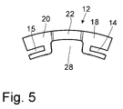
- the recess in the axial elevation 22 is not formed as an opening 16 but as a recess 28.
- the spring element 12 guides 14 and 15, which surround the retaining tabs 6 and provide a support to the diaphragm spring 4.
- the axial elevation 22 is supported on the retaining ring 5, so that again when worn the Game between diaphragm spring 4 and the surrounding components is balanced.
- the spring element 12 may also comprise two or more axial protrusions 22, each with a further support region arranged therebetween, so that four or more retaining tabs can be encompassed instead of the three gripped retaining tabs.
- a retaining tab 6 of the retaining ring 5 is pushed and bent by the middle recesses during assembly.
- the axial elevations 22 of the spring element 12 are compressed, so that a spring preload arises.
Landscapes
- Engineering & Computer Science (AREA)
- General Engineering & Computer Science (AREA)
- Mechanical Engineering (AREA)
- Mechanical Operated Clutches (AREA)
Applications Claiming Priority (1)
| Application Number | Priority Date | Filing Date | Title |
|---|---|---|---|
| DE102010028538.2A DE102010028538B4 (de) | 2010-05-04 | 2010-05-04 | Kupplungsbaugruppe mit Verschleißausgleich |
Publications (3)
| Publication Number | Publication Date |
|---|---|
| EP2385264A2 true EP2385264A2 (fr) | 2011-11-09 |
| EP2385264A3 EP2385264A3 (fr) | 2017-11-08 |
| EP2385264B1 EP2385264B1 (fr) | 2019-05-22 |
Family
ID=44352106
Family Applications (1)
| Application Number | Title | Priority Date | Filing Date |
|---|---|---|---|
| EP11160936.8A Active EP2385264B1 (fr) | 2010-05-04 | 2011-04-04 | Ensemble d'embrayage doté d'une compensation d'usure |
Country Status (3)
| Country | Link |
|---|---|
| US (1) | US8844699B2 (fr) |
| EP (1) | EP2385264B1 (fr) |
| DE (1) | DE102010028538B4 (fr) |
Cited By (1)
| Publication number | Priority date | Publication date | Assignee | Title |
|---|---|---|---|---|
| FR2988449A1 (fr) * | 2012-03-21 | 2013-09-27 | Valeo Embrayages | Mecanisme d'embrayage a positionnement du diaphragme simplifie |
Families Citing this family (4)
| Publication number | Priority date | Publication date | Assignee | Title |
|---|---|---|---|---|
| CN104455065A (zh) * | 2014-11-26 | 2015-03-25 | 长春一东离合器股份有限公司 | 膜片弹簧离合器的补偿机构 |
| US10132364B2 (en) | 2016-07-29 | 2018-11-20 | GM Global Technology Operations LLC | Backing plate providing axial stiffness |
| US10215237B2 (en) | 2016-07-29 | 2019-02-26 | GM Global Technology Operations LLC | Multiple-piece backing plate having parts made of different materials |
| CN107256294B (zh) * | 2017-05-24 | 2020-05-22 | 西安交通大学 | 一种基于等效刚度法的sss离合器动力学建模方法 |
Citations (3)
| Publication number | Priority date | Publication date | Assignee | Title |
|---|---|---|---|---|
| GB1511745A (en) | 1974-07-05 | 1978-05-24 | Ferodo Sa | Unitary assembly for a diaphragm spring clutch |
| DE102007053161A1 (de) | 2006-12-16 | 2008-06-19 | Zf Friedrichshafen Ag | Kupplungsvorrichtung |
| DE102007053724A1 (de) | 2006-12-16 | 2008-06-19 | Zf Friedrichshafen Ag | Kupplungsvorrichtung |
Family Cites Families (13)
| Publication number | Priority date | Publication date | Assignee | Title |
|---|---|---|---|---|
| US2117527A (en) * | 1934-11-19 | 1938-05-17 | Ernest E Wemp | Clutch member |
| DE1929823A1 (de) * | 1969-06-12 | 1970-12-17 | Mueller Hermann E Fa | Befestigungsbolzen fuer Tellerfedern |
| JPS582902Y2 (ja) * | 1975-05-14 | 1983-01-19 | アイシン精機株式会社 | プレツシヤ−プレ−トクツシヨンガタダイヤフラムスプリングクラツチ |
| FR2456877A1 (fr) | 1979-05-18 | 1980-12-12 | Ferodo Sa | Mecanisme d'embrayage a diaphragme |
| FR2459902A1 (fr) * | 1979-06-25 | 1981-01-16 | Ferodo Sa | Mecanisme d'embrayage a diaphragme notamment pour vehicule automobile |
| US5088583A (en) * | 1989-04-27 | 1992-02-18 | Kabushiki Kaisha Daikin Seisakusho | Clutch cover assembly with spring biased release assembly |
| FR2682170B1 (fr) * | 1991-10-02 | 1998-01-09 | Valeo | Embrayage a diaphragme, notamment pour vehicules automobiles. |
| FR2688557B1 (fr) * | 1992-03-10 | 1998-03-13 | Valeo | Mecanisme d'embrayage a diaphragme, notamment pour vehicule automobile et son procede de fabrication. |
| FR2722850B1 (fr) * | 1994-07-25 | 1996-09-06 | Valeo | Couvercle d'embrayage pour mecanisme d'embrayage a diaphragme, dont les pattes de butee permettent de distinguer les differents types de couvercle et mecanisme d'embrayage comportant un tel couvercle |
| DE19535712C1 (de) * | 1995-09-26 | 1996-10-31 | Fichtel & Sachs Ag | Reibungskupplung im Antriebsstrang eines Kraftfahrzeuges |
| EP0770788B1 (fr) * | 1995-10-24 | 2001-06-13 | Valeo | Module d'embrayage comportant des moyens perfectionnés de fixation de son couvercle sur le plateau de réaction |
| FR2775038B1 (fr) * | 1998-02-13 | 2000-10-27 | Valeo | Mecanisme d'embrayage, notamment pour vehicule automobile |
| DE10236809A1 (de) * | 2002-08-10 | 2004-02-19 | Zf Sachs Ag | Membranfeder für eine Reibungskupplung |
-
2010
- 2010-05-04 DE DE102010028538.2A patent/DE102010028538B4/de active Active
-
2011
- 2011-04-04 EP EP11160936.8A patent/EP2385264B1/fr active Active
- 2011-05-03 US US13/100,113 patent/US8844699B2/en active Active
Patent Citations (3)
| Publication number | Priority date | Publication date | Assignee | Title |
|---|---|---|---|---|
| GB1511745A (en) | 1974-07-05 | 1978-05-24 | Ferodo Sa | Unitary assembly for a diaphragm spring clutch |
| DE102007053161A1 (de) | 2006-12-16 | 2008-06-19 | Zf Friedrichshafen Ag | Kupplungsvorrichtung |
| DE102007053724A1 (de) | 2006-12-16 | 2008-06-19 | Zf Friedrichshafen Ag | Kupplungsvorrichtung |
Cited By (1)
| Publication number | Priority date | Publication date | Assignee | Title |
|---|---|---|---|---|
| FR2988449A1 (fr) * | 2012-03-21 | 2013-09-27 | Valeo Embrayages | Mecanisme d'embrayage a positionnement du diaphragme simplifie |
Also Published As
| Publication number | Publication date |
|---|---|
| EP2385264B1 (fr) | 2019-05-22 |
| DE102010028538A1 (de) | 2011-11-10 |
| US8844699B2 (en) | 2014-09-30 |
| US20110272235A1 (en) | 2011-11-10 |
| DE102010028538B4 (de) | 2020-09-03 |
| EP2385264A3 (fr) | 2017-11-08 |
Similar Documents
| Publication | Publication Date | Title |
|---|---|---|
| DE102011086995B4 (de) | Reibungskupplung mit Nachstelleinrichtung | |
| EP2385264B1 (fr) | Ensemble d'embrayage doté d'une compensation d'usure | |
| EP2446166A1 (fr) | Rondelle ondulée et dispositif de palier d'arbre | |
| DE2750334C2 (fr) | ||
| DE2121919B2 (de) | Reibungskupplung | |
| DE3222953A1 (de) | Kupplungsvorrichtung, insbesondere fuer kraftfahrzeuge | |
| DE112014001037B4 (de) | Reibungskupplung | |
| DE102006037023A1 (de) | Reibungskupplung | |
| EP1933050A1 (fr) | Dispositif d'embrayage | |
| DE102014213924A1 (de) | Lagereinrichtung für ein Kupplungssystem eines Kraftfahrzeugs | |
| EP1933051B1 (fr) | Dispositif d'embrayage | |
| DE102013203347A1 (de) | Tellerfeder und Reibungskupplung mit Tellerfeder | |
| WO2003031839A1 (fr) | Disque de frein pour un frein a disque | |
| DE102015214947B3 (de) | Reibungskupplungseinrichtung | |
| EP3085979A1 (fr) | Rondelle conique dotee de sections de butee de ressort integrees | |
| DE102019125989B4 (de) | Kupplungseinrichtung | |
| DE102016216934A1 (de) | Anpressplatte für eine Reibungskupplung und Reibungskupplung | |
| DE102013200556A1 (de) | Kupplungsvorrichtung | |
| DE102012216072A1 (de) | Nachstelleinrichtung für eine Reibungskupplung und entsprechende Reibungskupplung | |
| DE3422019A1 (de) | Reibungskupplung mit platzsparender anordnung der blattfedern | |
| DE102011016716A1 (de) | Kupplungsvorrichtung | |
| DE102008042001B4 (de) | Federeinheit in einer hydraulischen Servoeinrichtung für ein Reibeingriffselement | |
| DE10008604B4 (de) | Kraftübertragungssystem | |
| DE112017000320B4 (de) | Kupplungsdeckelanordnung | |
| DE102014216301B4 (de) | Kupplungsscheibe für eine Reibungskupplungseinrichtung |
Legal Events
| Date | Code | Title | Description |
|---|---|---|---|
| AK | Designated contracting states |
Kind code of ref document: A2 Designated state(s): AL AT BE BG CH CY CZ DE DK EE ES FI FR GB GR HR HU IE IS IT LI LT LU LV MC MK MT NL NO PL PT RO RS SE SI SK SM TR |
|
| AX | Request for extension of the european patent |
Extension state: BA ME |
|
| PUAI | Public reference made under article 153(3) epc to a published international application that has entered the european phase |
Free format text: ORIGINAL CODE: 0009012 |
|
| PUAL | Search report despatched |
Free format text: ORIGINAL CODE: 0009013 |
|
| AK | Designated contracting states |
Kind code of ref document: A3 Designated state(s): AL AT BE BG CH CY CZ DE DK EE ES FI FR GB GR HR HU IE IS IT LI LT LU LV MC MK MT NL NO PL PT RO RS SE SI SK SM TR |
|
| AX | Request for extension of the european patent |
Extension state: BA ME |
|
| RIC1 | Information provided on ipc code assigned before grant |
Ipc: F16D 13/58 20060101AFI20171003BHEP |
|
| STAA | Information on the status of an ep patent application or granted ep patent |
Free format text: STATUS: THE APPLICATION HAS BEEN PUBLISHED |
|
| STAA | Information on the status of an ep patent application or granted ep patent |
Free format text: STATUS: REQUEST FOR EXAMINATION WAS MADE |
|
| 17P | Request for examination filed |
Effective date: 20180809 |
|
| GRAP | Despatch of communication of intention to grant a patent |
Free format text: ORIGINAL CODE: EPIDOSNIGR1 |
|
| STAA | Information on the status of an ep patent application or granted ep patent |
Free format text: STATUS: GRANT OF PATENT IS INTENDED |
|
| INTG | Intention to grant announced |
Effective date: 20181113 |
|
| GRAS | Grant fee paid |
Free format text: ORIGINAL CODE: EPIDOSNIGR3 |
|
| GRAA | (expected) grant |
Free format text: ORIGINAL CODE: 0009210 |
|
| STAA | Information on the status of an ep patent application or granted ep patent |
Free format text: STATUS: THE PATENT HAS BEEN GRANTED |
|
| AK | Designated contracting states |
Kind code of ref document: B1 Designated state(s): AL AT BE BG CH CY CZ DE DK EE ES FI FR GB GR HR HU IE IS IT LI LT LU LV MC MK MT NL NO PL PT RO RS SE SI SK SM TR |
|
| REG | Reference to a national code |
Ref country code: GB Ref legal event code: FG4D Free format text: NOT ENGLISH |
|
| REG | Reference to a national code |
Ref country code: CH Ref legal event code: EP |
|
| REG | Reference to a national code |
Ref country code: IE Ref legal event code: FG4D Free format text: LANGUAGE OF EP DOCUMENT: GERMAN |
|
| REG | Reference to a national code |
Ref country code: DE Ref legal event code: R096 Ref document number: 502011015733 Country of ref document: DE |
|
| REG | Reference to a national code |
Ref country code: AT Ref legal event code: REF Ref document number: 1136481 Country of ref document: AT Kind code of ref document: T Effective date: 20190615 |
|
| REG | Reference to a national code |
Ref country code: NL Ref legal event code: MP Effective date: 20190522 |
|
| REG | Reference to a national code |
Ref country code: LT Ref legal event code: MG4D |
|
| PG25 | Lapsed in a contracting state [announced via postgrant information from national office to epo] |
Ref country code: NO Free format text: LAPSE BECAUSE OF FAILURE TO SUBMIT A TRANSLATION OF THE DESCRIPTION OR TO PAY THE FEE WITHIN THE PRESCRIBED TIME-LIMIT Effective date: 20190822 Ref country code: PT Free format text: LAPSE BECAUSE OF FAILURE TO SUBMIT A TRANSLATION OF THE DESCRIPTION OR TO PAY THE FEE WITHIN THE PRESCRIBED TIME-LIMIT Effective date: 20190922 Ref country code: FI Free format text: LAPSE BECAUSE OF FAILURE TO SUBMIT A TRANSLATION OF THE DESCRIPTION OR TO PAY THE FEE WITHIN THE PRESCRIBED TIME-LIMIT Effective date: 20190522 Ref country code: AL Free format text: LAPSE BECAUSE OF FAILURE TO SUBMIT A TRANSLATION OF THE DESCRIPTION OR TO PAY THE FEE WITHIN THE PRESCRIBED TIME-LIMIT Effective date: 20190522 Ref country code: NL Free format text: LAPSE BECAUSE OF FAILURE TO SUBMIT A TRANSLATION OF THE DESCRIPTION OR TO PAY THE FEE WITHIN THE PRESCRIBED TIME-LIMIT Effective date: 20190522 Ref country code: HR Free format text: LAPSE BECAUSE OF FAILURE TO SUBMIT A TRANSLATION OF THE DESCRIPTION OR TO PAY THE FEE WITHIN THE PRESCRIBED TIME-LIMIT Effective date: 20190522 Ref country code: SE Free format text: LAPSE BECAUSE OF FAILURE TO SUBMIT A TRANSLATION OF THE DESCRIPTION OR TO PAY THE FEE WITHIN THE PRESCRIBED TIME-LIMIT Effective date: 20190522 Ref country code: ES Free format text: LAPSE BECAUSE OF FAILURE TO SUBMIT A TRANSLATION OF THE DESCRIPTION OR TO PAY THE FEE WITHIN THE PRESCRIBED TIME-LIMIT Effective date: 20190522 Ref country code: LT Free format text: LAPSE BECAUSE OF FAILURE TO SUBMIT A TRANSLATION OF THE DESCRIPTION OR TO PAY THE FEE WITHIN THE PRESCRIBED TIME-LIMIT Effective date: 20190522 |
|
| PG25 | Lapsed in a contracting state [announced via postgrant information from national office to epo] |
Ref country code: GR Free format text: LAPSE BECAUSE OF FAILURE TO SUBMIT A TRANSLATION OF THE DESCRIPTION OR TO PAY THE FEE WITHIN THE PRESCRIBED TIME-LIMIT Effective date: 20190823 Ref country code: BG Free format text: LAPSE BECAUSE OF FAILURE TO SUBMIT A TRANSLATION OF THE DESCRIPTION OR TO PAY THE FEE WITHIN THE PRESCRIBED TIME-LIMIT Effective date: 20190822 Ref country code: RS Free format text: LAPSE BECAUSE OF FAILURE TO SUBMIT A TRANSLATION OF THE DESCRIPTION OR TO PAY THE FEE WITHIN THE PRESCRIBED TIME-LIMIT Effective date: 20190522 Ref country code: LV Free format text: LAPSE BECAUSE OF FAILURE TO SUBMIT A TRANSLATION OF THE DESCRIPTION OR TO PAY THE FEE WITHIN THE PRESCRIBED TIME-LIMIT Effective date: 20190522 |
|
| PG25 | Lapsed in a contracting state [announced via postgrant information from national office to epo] |
Ref country code: CZ Free format text: LAPSE BECAUSE OF FAILURE TO SUBMIT A TRANSLATION OF THE DESCRIPTION OR TO PAY THE FEE WITHIN THE PRESCRIBED TIME-LIMIT Effective date: 20190522 Ref country code: RO Free format text: LAPSE BECAUSE OF FAILURE TO SUBMIT A TRANSLATION OF THE DESCRIPTION OR TO PAY THE FEE WITHIN THE PRESCRIBED TIME-LIMIT Effective date: 20190522 Ref country code: EE Free format text: LAPSE BECAUSE OF FAILURE TO SUBMIT A TRANSLATION OF THE DESCRIPTION OR TO PAY THE FEE WITHIN THE PRESCRIBED TIME-LIMIT Effective date: 20190522 Ref country code: DK Free format text: LAPSE BECAUSE OF FAILURE TO SUBMIT A TRANSLATION OF THE DESCRIPTION OR TO PAY THE FEE WITHIN THE PRESCRIBED TIME-LIMIT Effective date: 20190522 Ref country code: SK Free format text: LAPSE BECAUSE OF FAILURE TO SUBMIT A TRANSLATION OF THE DESCRIPTION OR TO PAY THE FEE WITHIN THE PRESCRIBED TIME-LIMIT Effective date: 20190522 |
|
| REG | Reference to a national code |
Ref country code: DE Ref legal event code: R097 Ref document number: 502011015733 Country of ref document: DE |
|
| PG25 | Lapsed in a contracting state [announced via postgrant information from national office to epo] |
Ref country code: IT Free format text: LAPSE BECAUSE OF FAILURE TO SUBMIT A TRANSLATION OF THE DESCRIPTION OR TO PAY THE FEE WITHIN THE PRESCRIBED TIME-LIMIT Effective date: 20190522 Ref country code: SM Free format text: LAPSE BECAUSE OF FAILURE TO SUBMIT A TRANSLATION OF THE DESCRIPTION OR TO PAY THE FEE WITHIN THE PRESCRIBED TIME-LIMIT Effective date: 20190522 |
|
| PLBE | No opposition filed within time limit |
Free format text: ORIGINAL CODE: 0009261 |
|
| STAA | Information on the status of an ep patent application or granted ep patent |
Free format text: STATUS: NO OPPOSITION FILED WITHIN TIME LIMIT |
|
| PG25 | Lapsed in a contracting state [announced via postgrant information from national office to epo] |
Ref country code: TR Free format text: LAPSE BECAUSE OF FAILURE TO SUBMIT A TRANSLATION OF THE DESCRIPTION OR TO PAY THE FEE WITHIN THE PRESCRIBED TIME-LIMIT Effective date: 20190522 |
|
| 26N | No opposition filed |
Effective date: 20200225 |
|
| PG25 | Lapsed in a contracting state [announced via postgrant information from national office to epo] |
Ref country code: PL Free format text: LAPSE BECAUSE OF FAILURE TO SUBMIT A TRANSLATION OF THE DESCRIPTION OR TO PAY THE FEE WITHIN THE PRESCRIBED TIME-LIMIT Effective date: 20190522 |
|
| PG25 | Lapsed in a contracting state [announced via postgrant information from national office to epo] |
Ref country code: SI Free format text: LAPSE BECAUSE OF FAILURE TO SUBMIT A TRANSLATION OF THE DESCRIPTION OR TO PAY THE FEE WITHIN THE PRESCRIBED TIME-LIMIT Effective date: 20190522 |
|
| PGFP | Annual fee paid to national office [announced via postgrant information from national office to epo] |
Ref country code: BE Payment date: 20200316 Year of fee payment: 10 |
|
| PG25 | Lapsed in a contracting state [announced via postgrant information from national office to epo] |
Ref country code: MC Free format text: LAPSE BECAUSE OF FAILURE TO SUBMIT A TRANSLATION OF THE DESCRIPTION OR TO PAY THE FEE WITHIN THE PRESCRIBED TIME-LIMIT Effective date: 20190522 |
|
| REG | Reference to a national code |
Ref country code: CH Ref legal event code: PL |
|
| PG25 | Lapsed in a contracting state [announced via postgrant information from national office to epo] |
Ref country code: CH Free format text: LAPSE BECAUSE OF NON-PAYMENT OF DUE FEES Effective date: 20200430 Ref country code: LI Free format text: LAPSE BECAUSE OF NON-PAYMENT OF DUE FEES Effective date: 20200430 Ref country code: LU Free format text: LAPSE BECAUSE OF NON-PAYMENT OF DUE FEES Effective date: 20200404 |
|
| GBPC | Gb: european patent ceased through non-payment of renewal fee |
Effective date: 20200404 |
|
| PG25 | Lapsed in a contracting state [announced via postgrant information from national office to epo] |
Ref country code: IE Free format text: LAPSE BECAUSE OF NON-PAYMENT OF DUE FEES Effective date: 20200404 Ref country code: GB Free format text: LAPSE BECAUSE OF NON-PAYMENT OF DUE FEES Effective date: 20200404 |
|
| REG | Reference to a national code |
Ref country code: AT Ref legal event code: MM01 Ref document number: 1136481 Country of ref document: AT Kind code of ref document: T Effective date: 20200404 |
|
| PG25 | Lapsed in a contracting state [announced via postgrant information from national office to epo] |
Ref country code: AT Free format text: LAPSE BECAUSE OF NON-PAYMENT OF DUE FEES Effective date: 20200404 |
|
| REG | Reference to a national code |
Ref country code: BE Ref legal event code: MM Effective date: 20210430 |
|
| PG25 | Lapsed in a contracting state [announced via postgrant information from national office to epo] |
Ref country code: MT Free format text: LAPSE BECAUSE OF FAILURE TO SUBMIT A TRANSLATION OF THE DESCRIPTION OR TO PAY THE FEE WITHIN THE PRESCRIBED TIME-LIMIT Effective date: 20190522 Ref country code: CY Free format text: LAPSE BECAUSE OF FAILURE TO SUBMIT A TRANSLATION OF THE DESCRIPTION OR TO PAY THE FEE WITHIN THE PRESCRIBED TIME-LIMIT Effective date: 20190522 |
|
| PG25 | Lapsed in a contracting state [announced via postgrant information from national office to epo] |
Ref country code: MK Free format text: LAPSE BECAUSE OF FAILURE TO SUBMIT A TRANSLATION OF THE DESCRIPTION OR TO PAY THE FEE WITHIN THE PRESCRIBED TIME-LIMIT Effective date: 20190522 Ref country code: IS Free format text: LAPSE BECAUSE OF FAILURE TO SUBMIT A TRANSLATION OF THE DESCRIPTION OR TO PAY THE FEE WITHIN THE PRESCRIBED TIME-LIMIT Effective date: 20190922 |
|
| PG25 | Lapsed in a contracting state [announced via postgrant information from national office to epo] |
Ref country code: BE Free format text: LAPSE BECAUSE OF NON-PAYMENT OF DUE FEES Effective date: 20210430 |
|
| PGFP | Annual fee paid to national office [announced via postgrant information from national office to epo] |
Ref country code: FR Payment date: 20230309 Year of fee payment: 13 |
|
| P01 | Opt-out of the competence of the unified patent court (upc) registered |
Effective date: 20230528 |
|
| PG25 | Lapsed in a contracting state [announced via postgrant information from national office to epo] |
Ref country code: FR Free format text: LAPSE BECAUSE OF NON-PAYMENT OF DUE FEES Effective date: 20240430 |
|
| PG25 | Lapsed in a contracting state [announced via postgrant information from national office to epo] |
Ref country code: FR Free format text: LAPSE BECAUSE OF NON-PAYMENT OF DUE FEES Effective date: 20240430 |
|
| PGFP | Annual fee paid to national office [announced via postgrant information from national office to epo] |
Ref country code: DE Payment date: 20250305 Year of fee payment: 15 |