EP2385277B1 - Wärmetauscher - Google Patents
Wärmetauscher Download PDFInfo
- Publication number
- EP2385277B1 EP2385277B1 EP11163514.0A EP11163514A EP2385277B1 EP 2385277 B1 EP2385277 B1 EP 2385277B1 EP 11163514 A EP11163514 A EP 11163514A EP 2385277 B1 EP2385277 B1 EP 2385277B1
- Authority
- EP
- European Patent Office
- Prior art keywords
- heat exchanger
- base plate
- sealing element
- groove geometries
- component
- Prior art date
- Legal status (The legal status is an assumption and is not a legal conclusion. Google has not performed a legal analysis and makes no representation as to the accuracy of the status listed.)
- Not-in-force
Links
- 238000007789 sealing Methods 0.000 claims description 33
- 238000002485 combustion reaction Methods 0.000 claims description 12
- 229920001971 elastomer Polymers 0.000 claims description 2
- 239000000806 elastomer Substances 0.000 claims description 2
- 238000002347 injection Methods 0.000 claims description 2
- 239000007924 injection Substances 0.000 claims description 2
- 239000002184 metal Substances 0.000 description 6
- 239000003921 oil Substances 0.000 description 4
- 238000004519 manufacturing process Methods 0.000 description 3
- 238000004073 vulcanization Methods 0.000 description 3
- 230000001419 dependent effect Effects 0.000 description 2
- 238000000465 moulding Methods 0.000 description 2
- 238000005219 brazing Methods 0.000 description 1
- 238000009434 installation Methods 0.000 description 1
- 238000002955 isolation Methods 0.000 description 1
- 239000010687 lubricating oil Substances 0.000 description 1
- 238000003801 milling Methods 0.000 description 1
- 238000011085 pressure filtration Methods 0.000 description 1
- 229910000679 solder Inorganic materials 0.000 description 1
- 238000005476 soldering Methods 0.000 description 1
- 239000000243 solution Substances 0.000 description 1
Images
Classifications
-
- F—MECHANICAL ENGINEERING; LIGHTING; HEATING; WEAPONS; BLASTING
- F16—ENGINEERING ELEMENTS AND UNITS; GENERAL MEASURES FOR PRODUCING AND MAINTAINING EFFECTIVE FUNCTIONING OF MACHINES OR INSTALLATIONS; THERMAL INSULATION IN GENERAL
- F16J—PISTONS; CYLINDERS; SEALINGS
- F16J15/00—Sealings
- F16J15/02—Sealings between relatively-stationary surfaces
- F16J15/06—Sealings between relatively-stationary surfaces with solid packing compressed between sealing surfaces
- F16J15/10—Sealings between relatively-stationary surfaces with solid packing compressed between sealing surfaces with non-metallic packing
- F16J15/104—Sealings between relatively-stationary surfaces with solid packing compressed between sealing surfaces with non-metallic packing characterised by structure
- F16J15/106—Sealings between relatively-stationary surfaces with solid packing compressed between sealing surfaces with non-metallic packing characterised by structure homogeneous
-
- F—MECHANICAL ENGINEERING; LIGHTING; HEATING; WEAPONS; BLASTING
- F01—MACHINES OR ENGINES IN GENERAL; ENGINE PLANTS IN GENERAL; STEAM ENGINES
- F01M—LUBRICATING OF MACHINES OR ENGINES IN GENERAL; LUBRICATING INTERNAL COMBUSTION ENGINES; CRANKCASE VENTILATING
- F01M5/00—Heating, cooling, or controlling temperature of lubricant; Lubrication means facilitating engine starting
- F01M5/002—Cooling
-
- F—MECHANICAL ENGINEERING; LIGHTING; HEATING; WEAPONS; BLASTING
- F28—HEAT EXCHANGE IN GENERAL
- F28F—DETAILS OF HEAT-EXCHANGE AND HEAT-TRANSFER APPARATUS, OF GENERAL APPLICATION
- F28F9/00—Casings; Header boxes; Auxiliary supports for elements; Auxiliary members within casings
- F28F9/001—Casings in the form of plate-like arrangements; Frames enclosing a heat exchange core
- F28F9/002—Casings in the form of plate-like arrangements; Frames enclosing a heat exchange core with fastening means for other structures
-
- F—MECHANICAL ENGINEERING; LIGHTING; HEATING; WEAPONS; BLASTING
- F28—HEAT EXCHANGE IN GENERAL
- F28F—DETAILS OF HEAT-EXCHANGE AND HEAT-TRANSFER APPARATUS, OF GENERAL APPLICATION
- F28F2280/00—Mounting arrangements; Arrangements for facilitating assembling or disassembling of heat exchanger parts
- F28F2280/06—Adapter frames, e.g. for mounting heat exchanger cores on other structure and for allowing fluidic connections
Definitions
- the present invention relates to a heat exchanger with a base plate for attachment to a component, according to the preamble of claim 1.
- a generic heat exchanger with a base plate is known, via which this can be connected to another component, for example.
- On an internal combustion engine On an internal combustion engine.
- a metal plate with molded sealing elements is provided, so that the entire metal plate for sealing between the base plate of the heat exchanger and the other component, eg. The internal combustion engine, is used.
- an oil filter for lubricating oil of an internal combustion engine is known, which is also connected via a sealing plate to the internal combustion engine or sealed via this sealing plate with respect to the internal combustion engine.
- an oil filter element with a base plate is known, wherein a sealing element seals a pressure filtration unit on the one hand and on the other hand is arranged spaced from the base plate.
- a heat exchanger with an intermediate component is made of DE 20 2005 014 632 U1 known.
- the intermediate component is arranged on the heat carrier, wherein the intermediate component of the connection of the heat carrier is used with an internal combustion engine.
- the intermediate component has a plurality of openings and a channel, wherein the openings are each sealed by a sealing element.
- the EP 1 498 582 A2 discloses a generic heat exchanger for an internal combustion engine, which is connected by means of a flange to the internal combustion engine, wherein the flange serves as a base plate due to the planar design. Several openings or supply channels also lead through this base plate. Furthermore, the base plate has a groove in which a sealing element is arranged for sealing the supply channels. The sealing element can in this case be vulcanized in particular in the groove.
- the present invention is concerned with the problem of providing a heat exchanger of the generic type an improved embodiment, which is characterized in particular by a reduction in the variety of parts.
- the present invention is based on the general idea, for sealing a heat exchanger against another component, eg.
- another component eg.
- an internal combustion engine not as usual to use a separate metal plate with molded sealing elements, but to inject or vulcanize these sealing elements directly to a base plate of the heat exchanger and thereby produce a direct and at the same time tight connection to the component.
- the idea according to the invention can be thus save the previous and serving only as a support metal plate, whereby the variety of parts and thereby also an assembly cost can be reduced.
- Injection or vulcanization of the at least one sealing element on the base plate of the heat exchanger is usually carried out at a temperature which is well below a brazing temperature, so that no damage to a finished structure of the heat exchanger through the Anspritz- or Anvulkanisier mixes are to be feared.
- the base plate is composed of two layers, namely a first layer and a second layer soldered thereto, in which case the first layer contains the groove geometries in the form of through holes.
- the Nutengeometrien the first layer can be stamped and thus produced inexpensively and precisely. With the heat exchanger according to the invention can thus be reduced both the component costs and the assembly costs and thus generally the production costs.
- groove geometries are provided in the base plate of the heat exchanger, in which runs the at least one sealing element.
- the groove geometries can be embossed or milled, for example, in the base plate of the heat exchanger and predetermine the subsequent course of the at least one sealing element.
- By a particular undercut-like design of the groove geometry hooks the injected into these Nutengeometrien sealing element and is reliably held on the base plate in this way.
- the production of such groove geometries can be accomplished easily by means of appropriate milling tools.
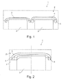
- a heat exchanger 1 has a base plate 2 for attachment to a further, not shown component, in particular for attachment to an internal combustion engine, wherein supply channels 3 lead through the base plate 2.
- at least one sealing element 4 is now molded or vulcanized directly onto the base plate 2, whereby a tight connection to the component, ie for example to the internal combustion engine, can be produced without a separate metal plate provided with sealing elements being required as usual.
- the sealing element 4 is made of plastic, in particular of an elastomer.
- grooves 5 or Nutengeometrien 5 are provided for receiving the sealing element, in which the sealing element 4 extends.
- the Nutengeometrien 5 can be formed like a channel, like this according to the Figures 1 and 2 is shown, or even undercut, whereby a toothing of the injected sealing element 4 with the Nutengeometrie 5 can be achieved.
- the grooves (geometries) 5 can be embossed or milled into the base plate 2, as for example, according to the Fig. 1 and according to the Fig. 2 , right side, is shown.
- the base plate 2 may also be constructed of two layers 6 and 7, namely a first layer 6 and a second layer 7 soldered thereto, in which case the first layer 6 contains the groove geometries 5 in the form of passage openings.
- the Nutengeometrien 5 of the first layer 6 can be stamped and thus manufactured inexpensively and precisely.
- the molding or vulcanization of the sealing elements 4 in the corresponding Nutengeometrien 5 is preferably carried out at a Anspritz- or scorch temperature, which is below the soldering temperature for connecting the two layers 6 and 7, so that the molding or vulcanization of at least one sealing element 4 at the base plate 2 has no negative influence on the solder joint between the two layers 6 and 7.
- the heat exchanger 1 may be connected to a filter, not shown, in particular to an oil filter, wherein the base plate 2 may theoretically also be part of such an oil filter, so that the saving of the previously required metallic plate with the molded sealing elements on other areas, such as the filter area, can be transmitted.
- heat exchanger 1 With the heat exchanger 1 according to the invention can be significantly reduced by saving the previously customary and required metal plate with the molded sealing elements, the variety of parts and thereby reduce both the manufacturing cost and installation costs.
Landscapes
- Engineering & Computer Science (AREA)
- General Engineering & Computer Science (AREA)
- Mechanical Engineering (AREA)
- Physics & Mathematics (AREA)
- Thermal Sciences (AREA)
- Lubrication Details And Ventilation Of Internal Combustion Engines (AREA)
- Lubrication Of Internal Combustion Engines (AREA)
- Heat-Exchange Devices With Radiators And Conduit Assemblies (AREA)
- Injection Moulding Of Plastics Or The Like (AREA)
- Gasket Seals (AREA)
Description
- Die vorliegende Erfindung betrifft einen Wärmetauscher mit einer Grundplatte zum Befestigen an einem Bauteil, gemäß dem Oberbegriff des Anspruchs 1.
- Aus der
DE 10 2006 027 725 A1 ist ein gattungsgemäßer Wärmetauscher mit einer Grundplatte bekannt, über welchen dieser an einem weiteren Bauteil, bspw. an einem Verbrennungsmotor, angebunden werden kann. Zwischen der Grundplatte und dem weiteren Bauteil ist dabei eine Metallplatte mit angespritzten Dichtelementen vorgesehen, sodass die gesamte Metallplatte zur Abdichtung zwischen der Grundplatte des Wärmetauschers und dem weiteren Bauteil, bspw. dem Verbrennungsmotor, herangezogen wird. - Aus der
DE 42 42 997 C1 ist ein Ölfilter für Schmieröl einer Brennkraftmaschine bekannt, welcher ebenfalls über eine Dichtplatte an der Brennkraftmaschine angeschlossen bzw. über diese Dichtplatte in Bezug auf die Brennkraftmaschine abgedichtet ist. - Aus der
FR 2 764 636 A1 - Ein Wärmetauscher mit einem Zwischenbauteil ist aus der
DE 20 2005 014 632 U1 bekannt. Das Zwischenbauteil ist am Wärmeträger angeordnet, wobei das Zwischenbauteil der Verbindung des Wärmeträgers mit einer Brennkraftmaschine dient. Das Zwischenbauteil weist mehrere Öffnungen sowie einen Kanal auf, wobei die Öffnungen jeweils durch ein Dichtelement abgedichtet werden. - Die
EP 1 498 582 A2 offenbart einen gattungsgemäßen Wärmetauscher für eine Brennkraftmaschine, der mit Hilfe eines Flansches mit der Brennkraftmaschine verbunden ist, wobei der Flansch aufgrund der ebenen Ausbildung als Grundplatte dient. Mehrere Öffnungen bzw. Versorgungskanäle führen zudem durch diese Grundplatte. Des Weiteren weist die Grundplatte eine Nut auf, in der ein Dichtelement zur Abdichtung der Versorgungskanäle angeordnet ist. Das Dichtelement kann hierbei insbesondere in die Nut einvulkanisiert sein. - Aus der
DE 86 24 855 U1 ist ein aus Kunststoff hergestellter Isolierflansch bekannt, der einen Grundkörper sowie ein Dichtelement aufweist, wobei der Grundkörper plattenartig ausgebildet ist. Der Isolierflansch dient hierbei der Isolierung von temperaturempfindlichen Teilen. Des Weiteren weist die Grundplatte eine Nut auf, in der das Dichtelement angeordnet ist. - Die vorliegende Erfindung beschäftigt sich mit dem Problem, für einen Wärmetauscher der gattungsgemäßen Art eine verbesserte Ausführungsform anzugeben, die sich insbesondere durch eine Reduzierung der Teilevielfalt auszeichnet.
- Dieses Problem wird erfindungsgemäß durch den Gegenstand des unabhängigen Anspruchs 1 gelöst. Vorteilhafte Ausführungsformen sind Gegenstand der abhängigen Ansprüche.
- Die vorliegende Erfindung beruht auf dem allgemeinen Gedanken, zum Abdichten eines Wärmetauschers gegenüber einem weiteren Bauteil, bspw. gegenüber einem Verbrennungsmotor, nicht wie bisher üblich eine separate Metallplatte mit angespritzten Dichtelementen zu verwenden, sondern diese Dichtelemente direkt an eine Grundplatte des Wärmetauschers anzuspritzen bzw. anzuvulkanisieren und dadurch eine direkte und gleichzeitig dichte Verbindung zum Bauteil herzustellen. Mit der erfindungsgemäßen Idee lässt sich somit die bisherige und lediglich als Träger dienende Metallplatte einsparen, wodurch die Teilevielfalt und dadurch auch ein Montageaufwand reduziert werden können. Das Anspritzen bzw. Anvulkanisieren des zumindest einen Dichtelementes an der Grundplatte des Wärmetauschers erfolgt dabei üblicherweise bei einer Temperatur die deutlich unterhalb einer Löttemperatur liegt, sodass keine Beschädigungen einer fertigen Struktur des Wärmetauschers durch den Anspritz- bzw. Anvulkanisierprozess zu befürchten sind. Die Grundplatte ist aus zwei Lagen, nämlich einer ersten Lage und einer damit verlöteten zweiten Lage aufgebaut, wobei in diesem Fall die erste Lage die Nutengeometrien in Form von Durchgangsöffnungen enthält. Die Nutengeometrien der ersten Lage können dabei gestanzt und damit kostengünstig und präzise hergestellt werden. Mit dem erfindungsgemäßen Wärmetauscher lassen sich somit sowohl die Bauteilkosten als auch die Montagekosten und damit generell die Herstellkosten reduzieren.
- Bei einer vorteilhaften Weiterbildung der erfindungsgemäßen Lösung, sind in der Grundplatte des Wärmetauschers Nutengeometrien vorgesehen, in welchen das zumindest eine Dichtelement verläuft. Die Nutengeometrien können dabei bspw. in die Grundplatte des Wärmetauschers eingeprägt oder eingefräst sein und den späteren Verlauf des zumindest einen Dichtelementes vorgeben. Durch eine insbesondere hinterschnittartige Ausbildung der Nutengeometrie verhakt sich das in diese Nutengeometrien eingespritzte Dichtelement und ist auf diese Weise zuverlässig an der Grundplatte gehalten. Das Herstellen derartiger Nutengeometrien kann dabei mittels entsprechender Fräswerkzeuge einfach bewerkstelligt werden.
- Weitere wichtige Merkmale und Vorteile der Erfindung ergeben sich aus den Unteransprüchen, aus den Zeichnungen und aus der zugehörigen Figurenbeschreibung anhand der Zeichnungen.
- Es versteht sich, dass die vorstehend genannten und die nachstehend noch zu erläuternden Merkmale nicht nur in der jeweils angegebenen Kombination, sondern auch in anderen Kombinationen oder in Alleinstellung verwendbar sind, ohne den Rahmen der vorliegenden Erfindung zu verlassen.
- Bevorzugte Ausführungsbeispiele der Erfindung sind in den Zeichnungen dargestellt und werden in der nachfolgenden Beschreibung näher erläutert, wobei sich gleiche Bezugszeichen auf gleiche oder ähnliche oder funktional gleiche Bauteile beziehen.
- Dabei zeigen, jeweils schematisch,
- Fig. 1
- einen Wärmetauscher mit einem erfindungsgemäß direkt an eine Grundplatte angespritzten Dichtelement,
- Fig. 2
- mögliche Ausführungsformen der Grundplatte.
- Entsprechend den
Figuren 1 und 2 , weist ein erfindungsgemäßer Wärmetauscher 1 eine Grundplatte 2 zum Befestigen an einem weiteren, nicht gezeigten Bauteil, insbesondere zum Befestigen an einem Verbrennungsmotor, auf, wobei durch die Grundplatte 2 Versorgungskanäle 3 führen. Erfindungsgemäß ist nun direkt an die Grundplatte 2 zumindest ein Dichtelement 4 angespritzt bzw. anvulkanisiert, wodurch eine dichte Verbindung zum Bauteil, d. h. beispielsweise zum Verbrennungsmotor, herstellbar ist, ohne dass wie bisher üblich eine separate mit Dichtelementen versehene Metallplatte erforderlich wäre. - Das Dichtelement 4 ist dabei aus Kunststoff, insbesondere aus einem Elastomer, ausgebildet. In der Grundplatte 2 sind zur Aufnahme des Dichtelementes 4 Nuten 5 bzw. Nutengeometrien 5 vorgesehen, in welchen das Dichtelement 4 verläuft. Die Nutengeometrien 5 können dabei kanalartig ausgebildet sein, wie dies gemäß den
Figuren 1 und 2 gezeigt ist, oder aber auch hinterschnittartig, wodurch eine Verzahnung des einzuspritzenden Dichtelementes 4 mit der Nutengeometrie 5 erreicht werden kann. - Die Nuten(-geometrien) 5 können dabei in die Grundplatte 2 eingeprägt oder eingefräst werden, wie dies bspw. gemäß der
Fig. 1 und gemäß derFig. 2 , rechte Seite, dargestellt ist. Alternativ hierzu kann die Grundplatte 2 auch aus zwei Lagen 6 und 7, nämlich einer ersten Lage 6 und einer damit verlöteten zweiten Lage 7 aufgebaut sein, wobei in diesem Fall die erste Lage 6 die Nutengeometrien 5 in Form von Durchgangsöffnungen enthält. Die Nutengeometrien 5 der ersten Lage 6 können dabei gestanzt und damit kostengünstig und präzise hergestellt werden. Das Anspritzen bzw. Anvulkanisieren der Dichtelemente 4 in den entsprechenden Nutengeometrien 5 erfolgt dabei vorzugsweise bei einer Anspritz- bzw. Anvulkanisierungstemperatur, die unterhalb der Löttemperatur zum Verbinden der beiden Lagen 6 und 7 liegt, sodass das Anspritzen bzw. Anvulkanisieren des zumindest einen Dichtelements 4 an der Grundplatte 2 keinen negativen Einfluss auf die Lötverbindung zwischen den beiden Lagen 6 und 7 hat. - Generell kann der Wärmetauscher 1 an einem nicht gezeigten Filter, insbesondere an einen Ölfilter, angeschlossen sein, wobei die Grundplatte 2 rein theoretisch auch Bestandteil eines derartigen Ölfilters sein kann, sodass das Einsparen der bisher erforderlichen metallischen Platte mit den angespritzten Dichtelementen auch auf andere Bereiche, wie bspw. den Filterbereich, übertragen werden kann.
- Gemäß der
Fig. 1 kann man das in die Nutengeometrie 5 eingespritzte Dichtelement 4 in der rechten Darstellung erkennen, wogegen in der linken Darstellung die noch leere Nutengeometrie 5 zu sehen ist. - Mit dem erfindungsgemäßen Wärmetauscher 1 lässt sich durch Einsparen der bisher üblichen und erforderlichen Metallplatte mit den daran angespritzten Dichtelementen die Teilevielfalt erheblich reduzieren und dadurch sowohl die Herstellungskosten als auch ein Montageaufwand reduzieren.
Claims (5)
- Wärmetauscher (1) mit einer Grundplatte (2) zum Befestigen an einem Bauteil, insbesondere an einem Verbrennungsmotor, wobei durch die Grundplatte (2) Versorgungskanäle (3) führen, wobei direkt an die Grundplatte (2) zumindest ein Dichtelement (4) angespritzt bzw. anvulkanisiert ist und dadurch eine dichte Verbindung zum Bauteil herstellbar ist, wobei in der Grundplatte (2) Nutengeometrien (5) vorgesehen sind, in welchen das zumindest eine Dichtelement (4) verläuft,
dadurch gekennzeichnet,- dass die Grundplatte (2) aus zwei Lagen (6,7) aufgebaut ist, wovon eine erste Lage (6) die Nutengeometrien (5) in Form von Durchgangsöffnungen enthält,- dass die Nutengeometrien (5) der ersten Lage (6) gestanzt sind, und/oder- dass die beiden Lagen (6,7) miteinander verlötet sind. - Wärmetauscher nach Anspruch 1,
dadurch gekennzeichnet,
dass das Dichtelement (4) aus Kunststoff, insbesondere aus einem Elastomer, ausgebildet ist. - Wärmetauscher nach Anspruch 1 oder 2,
dadurch gekennzeichnet,
dass die Nutengeometrien (5) hinterschnittartig ausgebildet sind. - Wärmetauscher nach einem der Ansprüche 1 bis 3,
dadurch gekennzeichnet,
dass die Nutengeometrien (5) eingeprägt oder eingefräst sind. - Wärmetauscher nach einem der Ansprüche 1 bis 4,
dadurch gekennzeichnet,
dass der Wärmetauscher (1) an einen Filter, insbesondere an einen Ölfilter, angeschlossen ist.
Applications Claiming Priority (1)
| Application Number | Priority Date | Filing Date | Title |
|---|---|---|---|
| DE202010006454U DE202010006454U1 (de) | 2010-05-05 | 2010-05-05 | Wärmetauscher |
Publications (2)
| Publication Number | Publication Date |
|---|---|
| EP2385277A1 EP2385277A1 (de) | 2011-11-09 |
| EP2385277B1 true EP2385277B1 (de) | 2013-06-12 |
Family
ID=42814141
Family Applications (1)
| Application Number | Title | Priority Date | Filing Date |
|---|---|---|---|
| EP11163514.0A Not-in-force EP2385277B1 (de) | 2010-05-05 | 2011-04-21 | Wärmetauscher |
Country Status (4)
| Country | Link |
|---|---|
| US (1) | US20110272129A1 (de) |
| EP (1) | EP2385277B1 (de) |
| JP (1) | JP5952529B2 (de) |
| DE (1) | DE202010006454U1 (de) |
Families Citing this family (3)
| Publication number | Priority date | Publication date | Assignee | Title |
|---|---|---|---|---|
| DE102013226434A1 (de) | 2013-12-18 | 2015-06-18 | MAHLE Behr GmbH & Co. KG | Wärmeübertrager |
| DE102016102893A1 (de) * | 2016-02-18 | 2017-08-24 | Webasto SE | Wärmetauschersystem |
| DE102020210838A1 (de) * | 2020-08-27 | 2022-03-03 | Mahle International Gmbh | Wärmeübertrageranordnung |
Family Cites Families (24)
| Publication number | Priority date | Publication date | Assignee | Title |
|---|---|---|---|---|
| DE8624855U1 (de) * | 1986-09-17 | 1987-11-12 | Klinger Ag, Zug | Isolierflansch |
| US5009779A (en) * | 1989-12-11 | 1991-04-23 | Hebert Alfred M | Magnetic element with magnesium coil for filter |
| US5209845A (en) * | 1991-06-11 | 1993-05-11 | Charles Sims | Seal for injection molded filter body |
| US5301958A (en) * | 1992-08-07 | 1994-04-12 | Dana Corporation | Seal for spin-on filter having circumferential retaining groove |
| DE4242997C1 (de) | 1992-12-18 | 1994-04-14 | Hengst Walter Gmbh & Co Kg | Brennkraftmaschine mit einem Ölfilter für deren Schmieröl |
| FR2764636B1 (fr) * | 1997-06-17 | 2000-11-10 | Ibs Filtran Kunststoff Metall | Cartouche de filtre a huile pour carters d'huile de moteurs ou d'engrenages |
| DE19736431C2 (de) * | 1997-08-21 | 2003-01-02 | Bruss Dichtungstechnik | Statische Dichtungsanordnung |
| JP3273752B2 (ja) * | 1997-11-11 | 2002-04-15 | 石川ガスケット株式会社 | ガスケットによるシール方法 |
| US20010045709A1 (en) * | 1999-10-28 | 2001-11-29 | Stobbart John Edward | Seal ring and joint |
| JP2001304784A (ja) * | 2000-04-19 | 2001-10-31 | Denso Corp | 熱交換器 |
| WO2002012686A1 (en) * | 2000-08-05 | 2002-02-14 | Jong Chul Gu | Oil filter assembly |
| US6544412B2 (en) * | 2001-03-28 | 2003-04-08 | Champion Laboratories, Inc. | Filter including temperature and pressure responsive bypass |
| US6729477B2 (en) * | 2002-05-03 | 2004-05-04 | Arvin Technologies, Inc. | Fluid filter retainer and seal apparatus |
| JP2004346916A (ja) * | 2003-05-26 | 2004-12-09 | Toyota Industries Corp | エンジンオイルクーラ及びその製造方法 |
| DE20310841U1 (de) * | 2003-07-14 | 2004-11-25 | Hengst Gmbh & Co.Kg | Modul für eine Brennkraftmaschine |
| US7234706B2 (en) * | 2004-07-08 | 2007-06-26 | International Engine Intellectual Property Company, Llc | Sealing system for multiple fluids |
| US7213814B2 (en) * | 2004-07-28 | 2007-05-08 | Federal-Mogul Worldwide, Inc. | Seal assembly |
| JP2006316680A (ja) * | 2005-05-11 | 2006-11-24 | Yamaha Motor Co Ltd | シール構造 |
| DE202005014632U1 (de) * | 2005-09-15 | 2007-02-01 | Hengst Gmbh & Co.Kg | Wärmetauscher mit Zwischenbauteil und Parallelventil |
| DE102005061186A1 (de) * | 2005-12-21 | 2007-06-28 | Mahle International Gmbh | Ölfiltereinrichtung für eine Brennkraftmaschine |
| JP2007250340A (ja) * | 2006-03-15 | 2007-09-27 | Ubukata Industries Co Ltd | 気密端子 |
| DE102006027725A1 (de) | 2006-06-16 | 2007-12-20 | Mahle International Gmbh | Einrichtung mit einem Wärmetauscher und einem Flüssigkeitsfilter |
| US7677228B2 (en) * | 2007-11-16 | 2010-03-16 | Manookian Jr Arman | Crankcase vapor purification device |
| US8272516B2 (en) * | 2007-11-19 | 2012-09-25 | Caterpillar Inc. | Fluid filter system |
-
2010
- 2010-05-05 DE DE202010006454U patent/DE202010006454U1/de not_active Expired - Lifetime
-
2011
- 2011-04-21 EP EP11163514.0A patent/EP2385277B1/de not_active Not-in-force
- 2011-04-28 JP JP2011101882A patent/JP5952529B2/ja not_active Expired - Fee Related
- 2011-05-04 US US13/100,668 patent/US20110272129A1/en not_active Abandoned
Also Published As
| Publication number | Publication date |
|---|---|
| DE202010006454U1 (de) | 2010-09-30 |
| US20110272129A1 (en) | 2011-11-10 |
| JP2011241821A (ja) | 2011-12-01 |
| JP5952529B2 (ja) | 2016-07-13 |
| EP2385277A1 (de) | 2011-11-09 |
Similar Documents
| Publication | Publication Date | Title |
|---|---|---|
| EP3963217A1 (de) | Befestigungsanordnung mit dämpfungswirkung und bauteilverbindung mit der befestigungsanordnung | |
| DE102007063255A1 (de) | Lagereinrichtung | |
| EP3648911B1 (de) | Verfahren zur herstellung einer kühlplatte | |
| DE102016115022A1 (de) | Bremsscheibe und Verfahren zu deren Herstellung | |
| EP2145121B1 (de) | Bauteil mit innen- und aussenverzahnung | |
| EP2478316A2 (de) | Plattenwärmetauscher | |
| EP2385277B1 (de) | Wärmetauscher | |
| WO2017036922A1 (de) | Kühlplatte eines batteriekühlers | |
| DE3002674C2 (de) | ||
| DE102007028259A1 (de) | Verbindung zwischen zwei einen runden Querschnitt aufweisenden Bauteilen eines Getriebes zur Aufnahme von Axialkräften | |
| DE102010050979A1 (de) | Verbindungsbereich zweier Bauteile, insbesondere zweier Fahrzeugrohbaukomponenten | |
| DE102014203102A1 (de) | Plattenwärmetauscher für ein Elektrokraftfahrzeug | |
| EP2331805B1 (de) | Filtereinrichtung für verbrennungsmotoren | |
| EP2611595B1 (de) | Luftansaugrohr | |
| EP3037150A1 (de) | Filtereinrichtung | |
| EP2270366A2 (de) | Verbindungsanordnung | |
| EP2161526A2 (de) | Verfahren zum Herstellen eines Plattenwärmetauschers, sowie nach diesem Verfahren hergestellter Plattenwärmetauscher | |
| DE102013111291A1 (de) | Kupplungslamelle | |
| DE102019132096B3 (de) | Einrichtung zum Kühlen von Batteriezellen | |
| EP2948656B1 (de) | Metallblech-flachdichtungslage sowie verfahren zu ihrer herstellung | |
| DE102008036882A1 (de) | Ventilnockenwelle | |
| DE102010002413A1 (de) | Metallschichtzylinderkopfdichtung | |
| EP2233189B1 (de) | Hohlschraube | |
| EP3102306A1 (de) | Filterelement, insbesondere luftfilterelement | |
| DE10235742B4 (de) | Verfahren zur Erzeugung eines Dichtbereiches an einer Flachdichtung, sowie Flachdichtung |
Legal Events
| Date | Code | Title | Description |
|---|---|---|---|
| AK | Designated contracting states |
Kind code of ref document: A1 Designated state(s): AL AT BE BG CH CY CZ DE DK EE ES FI FR GB GR HR HU IE IS IT LI LT LU LV MC MK MT NL NO PL PT RO RS SE SI SK SM TR |
|
| AX | Request for extension of the european patent |
Extension state: BA ME |
|
| PUAI | Public reference made under article 153(3) epc to a published international application that has entered the european phase |
Free format text: ORIGINAL CODE: 0009012 |
|
| 17P | Request for examination filed |
Effective date: 20120417 |
|
| GRAP | Despatch of communication of intention to grant a patent |
Free format text: ORIGINAL CODE: EPIDOSNIGR1 |
|
| RIC1 | Information provided on ipc code assigned before grant |
Ipc: F01M 11/03 20060101ALI20121127BHEP Ipc: F01M 5/00 20060101ALI20121127BHEP Ipc: F16J 15/10 20060101AFI20121127BHEP Ipc: F28F 9/00 20060101ALI20121127BHEP |
|
| GRAS | Grant fee paid |
Free format text: ORIGINAL CODE: EPIDOSNIGR3 |
|
| GRAA | (expected) grant |
Free format text: ORIGINAL CODE: 0009210 |
|
| AK | Designated contracting states |
Kind code of ref document: B1 Designated state(s): AL AT BE BG CH CY CZ DE DK EE ES FI FR GB GR HR HU IE IS IT LI LT LU LV MC MK MT NL NO PL PT RO RS SE SI SK SM TR |
|
| REG | Reference to a national code |
Ref country code: GB Ref legal event code: FG4D Free format text: NOT ENGLISH |
|
| REG | Reference to a national code |
Ref country code: CH Ref legal event code: EP |
|
| REG | Reference to a national code |
Ref country code: AT Ref legal event code: REF Ref document number: 616814 Country of ref document: AT Kind code of ref document: T Effective date: 20130615 |
|
| REG | Reference to a national code |
Ref country code: IE Ref legal event code: FG4D Free format text: LANGUAGE OF EP DOCUMENT: GERMAN |
|
| REG | Reference to a national code |
Ref country code: DE Ref legal event code: R096 Ref document number: 502011000893 Country of ref document: DE Effective date: 20130808 |
|
| PG25 | Lapsed in a contracting state [announced via postgrant information from national office to epo] |
Ref country code: LT Free format text: LAPSE BECAUSE OF FAILURE TO SUBMIT A TRANSLATION OF THE DESCRIPTION OR TO PAY THE FEE WITHIN THE PRESCRIBED TIME-LIMIT Effective date: 20130612 Ref country code: SI Free format text: LAPSE BECAUSE OF FAILURE TO SUBMIT A TRANSLATION OF THE DESCRIPTION OR TO PAY THE FEE WITHIN THE PRESCRIBED TIME-LIMIT Effective date: 20130612 Ref country code: FI Free format text: LAPSE BECAUSE OF FAILURE TO SUBMIT A TRANSLATION OF THE DESCRIPTION OR TO PAY THE FEE WITHIN THE PRESCRIBED TIME-LIMIT Effective date: 20130612 Ref country code: SE Free format text: LAPSE BECAUSE OF FAILURE TO SUBMIT A TRANSLATION OF THE DESCRIPTION OR TO PAY THE FEE WITHIN THE PRESCRIBED TIME-LIMIT Effective date: 20130612 Ref country code: ES Free format text: LAPSE BECAUSE OF FAILURE TO SUBMIT A TRANSLATION OF THE DESCRIPTION OR TO PAY THE FEE WITHIN THE PRESCRIBED TIME-LIMIT Effective date: 20130923 Ref country code: GR Free format text: LAPSE BECAUSE OF FAILURE TO SUBMIT A TRANSLATION OF THE DESCRIPTION OR TO PAY THE FEE WITHIN THE PRESCRIBED TIME-LIMIT Effective date: 20130913 Ref country code: NO Free format text: LAPSE BECAUSE OF FAILURE TO SUBMIT A TRANSLATION OF THE DESCRIPTION OR TO PAY THE FEE WITHIN THE PRESCRIBED TIME-LIMIT Effective date: 20130912 |
|
| REG | Reference to a national code |
Ref country code: NL Ref legal event code: VDEP Effective date: 20130612 |
|
| REG | Reference to a national code |
Ref country code: LT Ref legal event code: MG4D |
|
| PG25 | Lapsed in a contracting state [announced via postgrant information from national office to epo] |
Ref country code: BG Free format text: LAPSE BECAUSE OF FAILURE TO SUBMIT A TRANSLATION OF THE DESCRIPTION OR TO PAY THE FEE WITHIN THE PRESCRIBED TIME-LIMIT Effective date: 20130912 Ref country code: RS Free format text: LAPSE BECAUSE OF FAILURE TO SUBMIT A TRANSLATION OF THE DESCRIPTION OR TO PAY THE FEE WITHIN THE PRESCRIBED TIME-LIMIT Effective date: 20130612 Ref country code: HR Free format text: LAPSE BECAUSE OF FAILURE TO SUBMIT A TRANSLATION OF THE DESCRIPTION OR TO PAY THE FEE WITHIN THE PRESCRIBED TIME-LIMIT Effective date: 20130612 |
|
| PG25 | Lapsed in a contracting state [announced via postgrant information from national office to epo] |
Ref country code: LV Free format text: LAPSE BECAUSE OF FAILURE TO SUBMIT A TRANSLATION OF THE DESCRIPTION OR TO PAY THE FEE WITHIN THE PRESCRIBED TIME-LIMIT Effective date: 20130612 |
|
| PG25 | Lapsed in a contracting state [announced via postgrant information from national office to epo] |
Ref country code: IS Free format text: LAPSE BECAUSE OF FAILURE TO SUBMIT A TRANSLATION OF THE DESCRIPTION OR TO PAY THE FEE WITHIN THE PRESCRIBED TIME-LIMIT Effective date: 20131012 Ref country code: SK Free format text: LAPSE BECAUSE OF FAILURE TO SUBMIT A TRANSLATION OF THE DESCRIPTION OR TO PAY THE FEE WITHIN THE PRESCRIBED TIME-LIMIT Effective date: 20130612 Ref country code: CZ Free format text: LAPSE BECAUSE OF FAILURE TO SUBMIT A TRANSLATION OF THE DESCRIPTION OR TO PAY THE FEE WITHIN THE PRESCRIBED TIME-LIMIT Effective date: 20130612 Ref country code: PT Free format text: LAPSE BECAUSE OF FAILURE TO SUBMIT A TRANSLATION OF THE DESCRIPTION OR TO PAY THE FEE WITHIN THE PRESCRIBED TIME-LIMIT Effective date: 20131014 Ref country code: EE Free format text: LAPSE BECAUSE OF FAILURE TO SUBMIT A TRANSLATION OF THE DESCRIPTION OR TO PAY THE FEE WITHIN THE PRESCRIBED TIME-LIMIT Effective date: 20130612 |
|
| PG25 | Lapsed in a contracting state [announced via postgrant information from national office to epo] |
Ref country code: PL Free format text: LAPSE BECAUSE OF FAILURE TO SUBMIT A TRANSLATION OF THE DESCRIPTION OR TO PAY THE FEE WITHIN THE PRESCRIBED TIME-LIMIT Effective date: 20130612 Ref country code: NL Free format text: LAPSE BECAUSE OF FAILURE TO SUBMIT A TRANSLATION OF THE DESCRIPTION OR TO PAY THE FEE WITHIN THE PRESCRIBED TIME-LIMIT Effective date: 20130612 Ref country code: RO Free format text: LAPSE BECAUSE OF FAILURE TO SUBMIT A TRANSLATION OF THE DESCRIPTION OR TO PAY THE FEE WITHIN THE PRESCRIBED TIME-LIMIT Effective date: 20130612 |
|
| PLBE | No opposition filed within time limit |
Free format text: ORIGINAL CODE: 0009261 |
|
| STAA | Information on the status of an ep patent application or granted ep patent |
Free format text: STATUS: NO OPPOSITION FILED WITHIN TIME LIMIT |
|
| PG25 | Lapsed in a contracting state [announced via postgrant information from national office to epo] |
Ref country code: DK Free format text: LAPSE BECAUSE OF FAILURE TO SUBMIT A TRANSLATION OF THE DESCRIPTION OR TO PAY THE FEE WITHIN THE PRESCRIBED TIME-LIMIT Effective date: 20130612 |
|
| 26N | No opposition filed |
Effective date: 20140313 |
|
| PG25 | Lapsed in a contracting state [announced via postgrant information from national office to epo] |
Ref country code: IT Free format text: LAPSE BECAUSE OF FAILURE TO SUBMIT A TRANSLATION OF THE DESCRIPTION OR TO PAY THE FEE WITHIN THE PRESCRIBED TIME-LIMIT Effective date: 20130612 |
|
| REG | Reference to a national code |
Ref country code: DE Ref legal event code: R097 Ref document number: 502011000893 Country of ref document: DE Effective date: 20140313 |
|
| PG25 | Lapsed in a contracting state [announced via postgrant information from national office to epo] |
Ref country code: MC Free format text: LAPSE BECAUSE OF FAILURE TO SUBMIT A TRANSLATION OF THE DESCRIPTION OR TO PAY THE FEE WITHIN THE PRESCRIBED TIME-LIMIT Effective date: 20130612 Ref country code: LU Free format text: LAPSE BECAUSE OF FAILURE TO SUBMIT A TRANSLATION OF THE DESCRIPTION OR TO PAY THE FEE WITHIN THE PRESCRIBED TIME-LIMIT Effective date: 20140421 |
|
| REG | Reference to a national code |
Ref country code: CH Ref legal event code: PL |
|
| REG | Reference to a national code |
Ref country code: IE Ref legal event code: MM4A |
|
| PG25 | Lapsed in a contracting state [announced via postgrant information from national office to epo] |
Ref country code: LI Free format text: LAPSE BECAUSE OF NON-PAYMENT OF DUE FEES Effective date: 20140430 Ref country code: CH Free format text: LAPSE BECAUSE OF NON-PAYMENT OF DUE FEES Effective date: 20140430 |
|
| PG25 | Lapsed in a contracting state [announced via postgrant information from national office to epo] |
Ref country code: IE Free format text: LAPSE BECAUSE OF NON-PAYMENT OF DUE FEES Effective date: 20140421 |
|
| PG25 | Lapsed in a contracting state [announced via postgrant information from national office to epo] |
Ref country code: MT Free format text: LAPSE BECAUSE OF FAILURE TO SUBMIT A TRANSLATION OF THE DESCRIPTION OR TO PAY THE FEE WITHIN THE PRESCRIBED TIME-LIMIT Effective date: 20130612 |
|
| REG | Reference to a national code |
Ref country code: FR Ref legal event code: PLFP Year of fee payment: 6 |
|
| PG25 | Lapsed in a contracting state [announced via postgrant information from national office to epo] |
Ref country code: SM Free format text: LAPSE BECAUSE OF FAILURE TO SUBMIT A TRANSLATION OF THE DESCRIPTION OR TO PAY THE FEE WITHIN THE PRESCRIBED TIME-LIMIT Effective date: 20130612 |
|
| PG25 | Lapsed in a contracting state [announced via postgrant information from national office to epo] |
Ref country code: CY Free format text: LAPSE BECAUSE OF FAILURE TO SUBMIT A TRANSLATION OF THE DESCRIPTION OR TO PAY THE FEE WITHIN THE PRESCRIBED TIME-LIMIT Effective date: 20130612 |
|
| PG25 | Lapsed in a contracting state [announced via postgrant information from national office to epo] |
Ref country code: TR Free format text: LAPSE BECAUSE OF FAILURE TO SUBMIT A TRANSLATION OF THE DESCRIPTION OR TO PAY THE FEE WITHIN THE PRESCRIBED TIME-LIMIT Effective date: 20130612 Ref country code: HU Free format text: LAPSE BECAUSE OF FAILURE TO SUBMIT A TRANSLATION OF THE DESCRIPTION OR TO PAY THE FEE WITHIN THE PRESCRIBED TIME-LIMIT; INVALID AB INITIO Effective date: 20110421 Ref country code: BE Free format text: LAPSE BECAUSE OF FAILURE TO SUBMIT A TRANSLATION OF THE DESCRIPTION OR TO PAY THE FEE WITHIN THE PRESCRIBED TIME-LIMIT Effective date: 20140430 |
|
| REG | Reference to a national code |
Ref country code: FR Ref legal event code: PLFP Year of fee payment: 7 |
|
| REG | Reference to a national code |
Ref country code: AT Ref legal event code: MM01 Ref document number: 616814 Country of ref document: AT Kind code of ref document: T Effective date: 20160421 |
|
| PG25 | Lapsed in a contracting state [announced via postgrant information from national office to epo] |
Ref country code: AT Free format text: LAPSE BECAUSE OF NON-PAYMENT OF DUE FEES Effective date: 20160421 |
|
| REG | Reference to a national code |
Ref country code: FR Ref legal event code: PLFP Year of fee payment: 8 |
|
| PG25 | Lapsed in a contracting state [announced via postgrant information from national office to epo] |
Ref country code: MK Free format text: LAPSE BECAUSE OF FAILURE TO SUBMIT A TRANSLATION OF THE DESCRIPTION OR TO PAY THE FEE WITHIN THE PRESCRIBED TIME-LIMIT Effective date: 20130612 |
|
| PG25 | Lapsed in a contracting state [announced via postgrant information from national office to epo] |
Ref country code: AL Free format text: LAPSE BECAUSE OF FAILURE TO SUBMIT A TRANSLATION OF THE DESCRIPTION OR TO PAY THE FEE WITHIN THE PRESCRIBED TIME-LIMIT Effective date: 20130612 |
|
| PGFP | Annual fee paid to national office [announced via postgrant information from national office to epo] |
Ref country code: FR Payment date: 20200429 Year of fee payment: 10 |
|
| PG25 | Lapsed in a contracting state [announced via postgrant information from national office to epo] |
Ref country code: FR Free format text: LAPSE BECAUSE OF NON-PAYMENT OF DUE FEES Effective date: 20210430 |
|
| PGFP | Annual fee paid to national office [announced via postgrant information from national office to epo] |
Ref country code: GB Payment date: 20220419 Year of fee payment: 12 |
|
| PGFP | Annual fee paid to national office [announced via postgrant information from national office to epo] |
Ref country code: DE Payment date: 20230420 Year of fee payment: 13 |
|
| GBPC | Gb: european patent ceased through non-payment of renewal fee |
Effective date: 20230421 |
|
| PG25 | Lapsed in a contracting state [announced via postgrant information from national office to epo] |
Ref country code: GB Free format text: LAPSE BECAUSE OF NON-PAYMENT OF DUE FEES Effective date: 20230421 |
|
| PG25 | Lapsed in a contracting state [announced via postgrant information from national office to epo] |
Ref country code: GB Free format text: LAPSE BECAUSE OF NON-PAYMENT OF DUE FEES Effective date: 20230421 |
|
| REG | Reference to a national code |
Ref country code: DE Ref legal event code: R119 Ref document number: 502011000893 Country of ref document: DE |
|
| PG25 | Lapsed in a contracting state [announced via postgrant information from national office to epo] |
Ref country code: DE Free format text: LAPSE BECAUSE OF NON-PAYMENT OF DUE FEES Effective date: 20241105 |
|
| PG25 | Lapsed in a contracting state [announced via postgrant information from national office to epo] |
Ref country code: DE Free format text: LAPSE BECAUSE OF NON-PAYMENT OF DUE FEES Effective date: 20241105 |