EP2387231A2 - Appareil d'imagerie - Google Patents
Appareil d'imagerie Download PDFInfo
- Publication number
- EP2387231A2 EP2387231A2 EP11162439A EP11162439A EP2387231A2 EP 2387231 A2 EP2387231 A2 EP 2387231A2 EP 11162439 A EP11162439 A EP 11162439A EP 11162439 A EP11162439 A EP 11162439A EP 2387231 A2 EP2387231 A2 EP 2387231A2
- Authority
- EP
- European Patent Office
- Prior art keywords
- pickup device
- image pickup
- color
- image data
- light
- Prior art date
- Legal status (The legal status is an assumption and is not a legal conclusion. Google has not performed a legal analysis and makes no representation as to the accuracy of the status listed.)
- Withdrawn
Links
Images


Classifications
-
- H—ELECTRICITY
- H04—ELECTRIC COMMUNICATION TECHNIQUE
- H04N—PICTORIAL COMMUNICATION, e.g. TELEVISION
- H04N23/00—Cameras or camera modules comprising electronic image sensors; Control thereof
- H04N23/45—Cameras or camera modules comprising electronic image sensors; Control thereof for generating image signals from two or more image sensors being of different type or operating in different modes, e.g. with a CMOS sensor for moving images in combination with a charge-coupled device [CCD] for still images
-
- H—ELECTRICITY
- H04—ELECTRIC COMMUNICATION TECHNIQUE
- H04N—PICTORIAL COMMUNICATION, e.g. TELEVISION
- H04N23/00—Cameras or camera modules comprising electronic image sensors; Control thereof
- H04N23/10—Cameras or camera modules comprising electronic image sensors; Control thereof for generating image signals from different wavelengths
- H04N23/11—Cameras or camera modules comprising electronic image sensors; Control thereof for generating image signals from different wavelengths for generating image signals from visible and infrared light wavelengths
-
- H—ELECTRICITY
- H04—ELECTRIC COMMUNICATION TECHNIQUE
- H04N—PICTORIAL COMMUNICATION, e.g. TELEVISION
- H04N23/00—Cameras or camera modules comprising electronic image sensors; Control thereof
- H04N23/20—Cameras or camera modules comprising electronic image sensors; Control thereof for generating image signals from infrared radiation only
- H04N23/21—Cameras or camera modules comprising electronic image sensors; Control thereof for generating image signals from infrared radiation only from near infrared [NIR] radiation
-
- H—ELECTRICITY
- H04—ELECTRIC COMMUNICATION TECHNIQUE
- H04N—PICTORIAL COMMUNICATION, e.g. TELEVISION
- H04N23/00—Cameras or camera modules comprising electronic image sensors; Control thereof
- H04N23/50—Constructional details
- H04N23/55—Optical parts specially adapted for electronic image sensors; Mounting thereof
-
- H—ELECTRICITY
- H04—ELECTRIC COMMUNICATION TECHNIQUE
- H04N—PICTORIAL COMMUNICATION, e.g. TELEVISION
- H04N23/00—Cameras or camera modules comprising electronic image sensors; Control thereof
- H04N23/80—Camera processing pipelines; Components thereof
- H04N23/84—Camera processing pipelines; Components thereof for processing colour signals
-
- H—ELECTRICITY
- H04—ELECTRIC COMMUNICATION TECHNIQUE
- H04N—PICTORIAL COMMUNICATION, e.g. TELEVISION
- H04N23/00—Cameras or camera modules comprising electronic image sensors; Control thereof
- H04N23/95—Computational photography systems, e.g. light-field imaging systems
-
- H—ELECTRICITY
- H04—ELECTRIC COMMUNICATION TECHNIQUE
- H04N—PICTORIAL COMMUNICATION, e.g. TELEVISION
- H04N23/00—Cameras or camera modules comprising electronic image sensors; Control thereof
- H04N23/95—Computational photography systems, e.g. light-field imaging systems
- H04N23/951—Computational photography systems, e.g. light-field imaging systems by using two or more images to influence resolution, frame rate or aspect ratio
-
- H—ELECTRICITY
- H04—ELECTRIC COMMUNICATION TECHNIQUE
- H04N—PICTORIAL COMMUNICATION, e.g. TELEVISION
- H04N9/00—Details of colour television systems
- H04N9/77—Circuits for processing the brightness signal and the chrominance signal relative to each other, e.g. adjusting the phase of the brightness signal relative to the colour signal, correcting differential gain or differential phase
- H04N9/78—Circuits for processing the brightness signal and the chrominance signal relative to each other, e.g. adjusting the phase of the brightness signal relative to the colour signal, correcting differential gain or differential phase for separating the brightness signal or the chrominance signal from the colour television signal, e.g. using comb filter
Definitions
- the present invention relates to an imaging apparatus.
- the wide-area surveillance camera that takes an image of outdoor etc. is mainly requested for the following three conditions.
- a first condition to be requested is to image clearly a subject to be noted even in a shooting condition in which the subject is hard to be seen due to the fog, the mist, or the like.
- a second condition is to image the subject even in a dark environment with low illuminance.
- a third condition is to obtain a color image because identification by color information, such as color of clothes, may be important in many cases.
- a scattering intensity is proportional to the inverse 4th power of the light wavelength.
- the Mie theory will be applied to a grain size of fog, or the like, which is about 1000nm to 50 ⁇ m in diameter, and the scattering intensity is proportional to about the inverse square of the light wavelength.
- wavelengths of blue or green light in particular tend to be more scattered, and wavelengths of blue or green light don't reach a camera. Therefore, an image took by a camera that receives visible lights is close to a state visible to the human eye, and the subject in the distance will be hazy with low visibility.
- the single-chip color image pickup device is mounted with a red, green, blue color filter in front of the photodetector, the sensibility of the photodetector of each color of the red, green, and blue will be lower than the sensibility of a monochrome image pickup device.
- a method for example, a night-mode imaging
- a night-mode imaging for temporarily saving an IR cutoff filter set in front of an image pickup device and for illuminating the subject by infrared light in order to compensate low sensibility in imaging in a dark environment with low illuminance.
- infrared imaging it is difficult to image a color image, and it is also difficult to improve the sensitivity substantially since it has to be passed through the red, green and blue filter in front of the photodetector in the infrared imaging.
- a single-chip monochrome image pickup device is capable of imaging an image with higher sensitivity and higher spatial resolution than the single-chip color image pickup device.
- the monochrome image pickup device is not capable of obtaining color information, the above-mentioned third condition is not to be fulfilled.
- JP 2007-110209A discloses an imaging apparatus which has both a monochrome image pickup device and a color image pickup device respectively, and which is further mounted with an optical element for splitting an incoming light and for irradiating the split lights on the monochrome image pickup device and the color image pickup device respectively.
- the optical element according to JP 2007-110209 is, however, is a half mirror to spilt the incoming light into a reflected light and a transmitted light, and wavelength components of the reflected light and the transmitted light are the same. Therefore, wavelength components of lights incoming to the monochrome image pickup device and the color image pickup device are the same.
- JP 2007-110209A has an issue that it cannot qualify the above first condition to image a subject clearly since it used an image data contained visible light when extracting the luminance information.
- an imaging apparatus which is novel and improved, and which is capable of imaging a subject even in a shooting condition in which the subject is hard to be seen due to the haze or the like, or in a dark environment with low illuminance, and capable of obtaining color images.
- an image apparatus including an optical elements that disperses an incoming light from a subject into a first light composed of wavelength components in a visible light region only, and a second light which does not contain the first light and which is composed of wavelength components in other than visible light region only, a color image pickup device that receives the first light irradiated from the optical element, and a monochrome image pickup device that receives the second light irradiated from the optical element.
- the optical element may be a spectrum mirror that reflects the first light and transmits the second light.
- Mn Mn ⁇ Cn where the number of pixels of the color image pickup device is Cn and the number of pixels of the monochrome image pickup device is Mn.
- the imaging apparatus may include an image acquisition unit that obtains color image data from the color image pickup device, and a monochrome image data from the monochrome image device, a color information extraction unit that extracts color information from the color image data, a luminance information extraction unit that extracts luminance information from the monochrome image data, and a synthesis unit that synthesizes the extracted color information and the extracted luminance information to generate composite image data.
- the color image pickup device and the monochrome image pickup device may be positioned so that a subject image of the color image data matches a subject image of the monochrome image data.
- the present invention it is possible to image a subject in a shooting condition in which the subject is hard to be seen due to the fog or the like, or in a dark environment with low illuminance and to obtain a color image.
- the imaging apparatus 100 includes a built-in image processing apparatus 102 as a signal processing circuit.
- FIG. 1 is a block diagram for illustrating the imaging apparatus 100 according to the embodiment.
- the imaging apparatus 100 includes, for example, an optical system 101 and the image processing apparatus 102.
- the optical system 101 sends the color image data and the monochrome image data separately to the image processing apparatus 102 as shown in FIG. 1 .
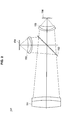
- FIG. 2 is an explanatory diagram for illustrating the optical system 101 according to the embodiment.
- FIG. 2 shows a schematic overview of each of optical components and an optical path.
- the optical system 101 includes a front lens 151, a spectrum mirror 152, a lens group 153, a color image pickup device 154, a lens group 155, and a monochrome image pickup device 156, or the like.
- the spectrum mirror 152 disperses into a first light composed of wavelength components in a visible light region only, and a second light which does not contain the first light and which is composed of wavelength components in other than the visible light region only.
- the color image pickup device 154 receives the first light irradiated from an optical element
- the monochrome image pickup device 156 receives the second light irradiated from the optical element.
- the front lens 151 receives lights reflected on a subject, transmits and refracts the lights came from the subject to irradiate the lights on the spectrum mirror 152.
- the spectrum mirror 152 is evaporated a dichroic film on its surface.
- the spectrum mirror 152 reflects wavelength elements in the visible light region, such as wavelength elements in the visible light region equal to or less than 675nm, for example, among incoming lights, and transmits wavelength elements in other than the visible light region, such as near-infrared light wavelength elements equal to or more than 675nm, for example, among the incoming lights.
- the wavelength elements equal to or less than 675nm is transmitted through the lens group 153, is irradiated on the color image pickup device 154 to form an image.
- threshold value for the wavelength elements dispersed by the spectrum mirror 152 is not limited to 675nm, but may be other value.
- FIG. 5 is a graph for illustrating a spectral reflectance of light that is reflected on the spectrum mirror 152.
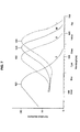
- the spectrum mirror 152 leads lights mainly being equal to or less than wavelength 675nm to the color image pickup device 154. Since it is understood that a spectral sensitivity of human eye is indicated like FIG. 7 , the wavelength of lights lead by the color image pickup device 154 may be generally within the visible light region.
- FIG. 7 is a graph for illustrating an absorption spectrum of visual pigment that is contained by cone cells (S, M, L) and rod cells (R) of a human body.
- FIG. 6 is a graph for illustrating a spectral transmittance of light that is transmitted through a spectrum mirror 152.
- the spectrum mirror 152 leads lights mainly being equal to or more than wavelength 675nm to the monochrome image pickup device 156.
- the wavelength of lights lead by the monochrome image pickup device 156 may be generally within other than the visible light region.
- optical components including an imaging lens has efficient transmittance in the wavelength in the range of 400nm to 1100nm, and never shield lights reached to the color image pickup device 154 and the monochrome image pickup device 156.
- the color image pickup device 154 and the monochrome image pickup device 156 various types of solid-state image pickup devices, such as a CCD solid-state image pickup device, a MOS solid-state image pickup device, a CMOS solid-state image pickup device, or the like, can be used.
- the color image pickup device 154 is an image pickup device which is mounted with a red, green, blue color filter in front of a photodetector, and which outputs color image data composed of red-color components, green-color components, and blue-color components.
- the monochrome image pickup device 156 is an image pickup device which is not mounted with a color filter in front of a photodetector, and which outputs monochrome image data composed of luminance information.
- FIG. 8 is a graph for illustrating a spectral sensitivity characteristic of a color image pickup device 154. It can be understood that the wavelength region equal to or less than wavelength 675nm of the wavelength, which has been reflected on the spectrum mirror 152 and incoming to the color image pickup device 154 as illustrated in FIG. 5 , matches to the region where the color image pickup device 154 shown in FIG. 8 has the spectral sensitivity. Therefore, the color image pickup device 154 is capable of catching the visible lights without loss.
- FIG. 9 is a graph for illustrating a spectral sensitivity characteristic of a monochrome image pickup device 156.
- the monochrome image pickup device 156 shows the maximum sensitivity in the visible light region, it still has efficient sensitivity in the near-infrared light region in the range of wavelength 675nm to 1000nm. Therefore, the monochrome image pickup device 156 can receive the wavelength components whose wavelength is equal to or longer than 675nm, which is longer than the visible light transmitted through the spectrum mirror 152 and incoming to the monochrome image pickup device 156.
- the color image pickup device 154 and the monochrome image pickup device 156 are positioned so that a subject image of the color image data matches a subject image of the monochrome image data.
- the positioning for matching the subject images may be performed by a mechanical method, by a method using software at the time of image synthesis, and by both of methods.
- the optical sizes of the color image pickup device 154 and the monochrome image pickup device 156 are almost same. In such configuration, there is an advantage that view angles, depths of focus, and imaging regions are almost same in two optical systems which have been split by the spectrum mirror 152 without adjusting in particular.
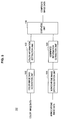
- FIG. 3 is a block diagram for illustrating the image processing apparatus 102 according to the embodiment of the present invention.
- the image processing apparatus 102 extracts color information from color image data composed of wavelength components in a visible light region only, extracts luminance information from monochrome image data which does not contain the wavelength components in the visible light region and which is composed of wavelength components in other than visible light region only, and synthesizes the color information and the luminance information to generate image data. This makes it possible to obtain an image data in which a subject is displayed clearly since an image data contained visible light is not used when extracting the luminance information.
- the image processing apparatus 102 includes a color image data acquisition unit 112, a monochrome image data acquisition unit 114, a color information extraction unit 122, a luminance information extraction unit 124, and a synthesis unit 130, or the like.
- the color image data acquisition unit 112 is an example of an image acquisition unit that obtains color image data obtained as the result of imaging using a color image pickup device.
- the color image pickup device is an image pickup device which is mounted with a red, green, blue color filter in front of the photodetector, and which outputs color image data composed of red-color components, green-color components, and blue-color components.
- the color image data acquisition unit 112 sends the color image data composed of wavelength components in the visible light region only as it is to the color information extraction unit 122.
- the color image data acquisition unit 112 removes the wavelength components other than in the visible light region, and sends the color image data composed of wavelength components in the visible light region only, to the color information extraction unit 122.
- the monochrome image data acquisition unit 114 is an example of the image acquisition unit and obtains monochrome image data obtained as the result of imaging using monochrome image pickup device.
- the monochrome image pickup device is an image pickup device which is not mounted with a color filter in front of a photodetector, and which outputs monochrome image data composed of luminance information. Since the monochrome image pickup device is not mounted with a color filter, it has higher sensitivity and is capable of imaging with higher spatial resolution than the color image pickup device.
- the monochrome image data acquisition unit 114 sends the monochrome image data composed of wavelength components other than in the visible light region only as it is to the luminance information extraction unit 124.
- the monochrome image data acquisition unit 114 removes the wavelength components in the visible light, and sends the monochrome image data composed of wavelength components other than in the visible light region only to the luminance information extraction unit 124.
- the above-mentioned color image data may be composed of only wavelength components equals to or less than a predetermined value, 675nm, for example, and the monochrome image data may be composed of wavelength components equals to or more than the predetermined value, 675nm, for example.
- the predetermined value is not limited to the above examples.
- the color image data may contain wavelength components in the range of 400nm to 700nm
- the monochrome image data may contain wavelength components in the range of 700nm to 1000nm.
- the color image data may contain wavelength components whose a half-value wavelength on a short-wavelength side is in the range of 420nm to 460nm and a half-value wavelength on the long-wavelength side is in the range of 610nm to 650nm, and the monochrome image data may contain wavelength components whose a half-value wavelength on a short-wavelength side is in the range of 650nm to 750nm.
- the color information extraction unit 122 decomposes the color image data received from the color image data acquisition unit 112, the color image data which is composed of wavelength components in the visible light region only, into luminance information Y1 and color difference information Cb and Cr, and extracts the color difference information Cb and Cr.
- the color difference information Cb and Cr are examples of color information.
- the color information extraction unit 122 sends the extracted color difference information Cb and Cr to the synthesis unit 130.
- the luminance information Y1 is not necessarily to be sent to the synthesis unit 130 since it is not to be used for the processing of synthesis in the synthesis unit 130.
- each of RGB is represented by 8 bits into the luminance information Y1 and the color difference information Cb and Cr
- the following mathematical formulas 1 to 3 can be used for converting RGB signals to YCbCr signals.
- the luminance information extraction unit 124 extracts the monochrome image data received from the monochrome image data acquisition unit 114, the monochrome image data which is composed of wavelength components other than in a visible light region only, as the luminance information Y2.
- the luminance information extraction unit 124 sends the extracted luminance information Y2 to the synthesis unit 130.
- the synthesis unit 130 synthesizes the color difference information Cb and Cr that are received from the color information extraction unit 122 and the luminance information Y2 that is received from the luminance information extraction unit 124, and generates composite image data.
- the following formulas 4 to 6 can be used for converting YCbCr signals to RGB signals.
- FIG. 4 is a flow chart for illustrating a synthesis processing of the image processing apparatus 102 according to the embodiment.
- the image processing apparatus 102 obtains color image data composed of wavelength components in a visible light region only and monochrome image data composed of wavelength components other than in the visible light region only (step S1).
- the color image data is decomposed into the luminance information Y1 and the color difference information Cb and Cr, and the color difference information Cb and Cr are extracted from the color image data. Further, the luminance information Y2 is extracted from the monochrome image data (step S2).
- step S3 the color difference information Cb and Cr extracted from the color image data and the luminance information Y2 extracted from the monochrome image data are to be synthesized, and composite image data is to be generated.
- the imaging apparatus 100 of the present embodiment can obtain an optimal result by being applied to a wide-area surveillance camera, for example. According to the present embodiment, it is possible to satisfy the following three conditions particularly for the wide-area surveillance camera.
- a first condition to be requested is to image clearly a subject to be noted even in a shooting condition in which the subject is difficult to be seen due to the fog, the mist, or the like.
- a second condition is to image the subject even in a dark environment with low illuminance.
- a third condition is to obtain a color image because identification by color information, such as color of clothes, may be often important in many cases.
- the first condition is described. It is important that lights reflected on a subject can be reached to an image pickup device without being decreased in order to image the subject clearly.
- the near-infrared light (NIR) of wavelength in the range of 675nm to 1000nm longer than the visible light is used.
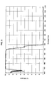
- FIG. 10 is a graph for illustrating a relationship between scattering volume and wavelength according to the Rayleigh scattering formula.
- the scattering intensity is proportional to the inverse 4th power of the light wavelength where d ⁇ ⁇ / ⁇ .
- n a particle count
- smog d 1nm to 1000nm)
- m reflection coefficient
- ⁇ wavelength of light.
- the reflection coefficient m is given in natural conditions, and the wavelength of light ⁇ can be varied depending on a design condition of the imaging apparatus 100.
- the near-infrared light has smaller scattering volume than the visible light in the range of wavelength 400nm to 675nm. For that reason, in the air, or in the environment where airborne particles whose diameter is equal to or less than about one third of the light wavelength are floating, even under the shooting condition in which the subject is difficult to be seen due to the fog, the mist, or the like, it is possible to image the subject to be noted more clearly than an ordinary camera, by applying to the technology of the present embodiment.
- the scattering volume is proportional in the range of the 0 to the inverse square of the light wavelength.
- the near-infrared light NIR
- the present embodiment using the near-infrared light (NIR) makes it possible to image the subject even in the environment of the fog more clearly than the ordinary camera.
- the present embodiment uses the near-infrared light (NIR) which the ordinary color camera does not use, and has an advantage at the low illuminance since NIR is included in the lights at dusk or artificial lightning.
- NIR near-infrared light
- the present embodiment uses the monochrome image pickup device 156 which is capable of imaging with higher sensitivity and higher spatial resolution than the color image pickup device 154. Therefore, the present embodiment has an advantage at the low illuminance.
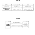
- FIG. 11 is a table for illustrating an example of sensitivity and minimum subject illuminance of a monochrome camera and a color camera. This is an example of comparison between a color camera which is mounted with a RGB color filter in front of the same photodetector and a monochrome camera which is not mounted with a color filter in front of the photodetector. It is understood that the monochrome camera has a higher sensitivity and lower minimum subject illuminance comparing to the color camera. Since the color image pickup device is mounted with a RGB color filter in front of the photodetector, any pixel of each color of RGB has lower sensitivity comparing to the monochrome image pickup device.
- the third condition will be explained.
- color image will be obtained.
- the monochrome image pickup device can image at low illuminance, however, obviously it is difficult to obtain color information.
- the present embodiment uses both color information obtained from the color image pickup device 154 and luminance information obtained from the monochrome image pickup device to meet both the first and the second conditions, as well as satisfying the third condition to image color imaging.
- FIG. 12 is a block diagram for illustrating the imaging apparatus 200 and the image processing apparatus 102 according to a modified example of the embodiment of the present invention.
- the image processing apparatus 102 may be a personal computer, a server apparatus, or the like.
- the imaging apparatus 200 includes the above-described optical system 101, and outputs color image data composed of the wavelength components in the visible light region only and monochrome image data which does not include the wavelength components in the visible light region and is composed of the wavelength components in other than the visible light region only.
- timing for executing the above-described image processing is not particularly limited and may be various timings, such as in real-time, after the completion of imaging, or the like.
- the imaging processing is to be performed in real-time, it is possible to create a composite image in a short period of time since it performs signal processing on image data obtained by imaging with the color image pickup device 154 and the monochrome image pickup device 156.
- the imaging apparatus 100 according to the first embodiment described above or the imaging apparatus 200 according to the modified embodiment have an advantage that the parallax disparity or the focal shift do not occur, since the monochrome image pickup device 156 and the color image pickup device 154 shares a camera in common.
- Connections between the color image pickup device 154 and the monochrome image pickup device 156 with the image processing apparatus 102 or with a recording apparatus as the recording medium may be configured to exchange data through wire (such as a cable, telephone line, for example) or wireless.
- wire such as a cable, telephone line, for example
- wireless such as a wireless fidelity
- a server apparatus on a network intranet, internet, or the like
- software for performing the image processing so that the software can be accessed through the network to perform signal processing on images photographed by the color image pickup device 154 or the monochrome image pickup device 156.
- the spectrum mirror 152 for splitting incoming lights is arranged between the front lens 151 and the lens groups 153 and 155, however, in the present invention, there is no limitation on where to place an optical element for splitting the incoming lights, and it can be placed at another place. For example, it may be placed between the lens groups, or between a lens group and an image pickup device. Further, in stead of arranging a front lens, a lens with having the same function may be arranged in front of each lens group so that incoming lights can be split initially by the optical elements.
- the front lens 151 is used in common. In this case, there is an advantage that influences such as aberration of the front lens 151 becomes even, and that it becomes possible to apply what are used in an ordinary camera without a change as the lens groups 153 and 155.
- the optical element for splitting the incoming lights is not limited to the spectrum mirror 152, but may be other optical element, such as a combination of prism, or the like.
- the number of split optical paths is not limited to two, but it may be three or more to be split in total. That is, an imaging apparatus may be configured by having a plurality of color image pickup devices or monochrome image pickup devices.
- an example of the color image pickup device may be a three-chip color image pickup device mounted with an image pickup device for each color of R, G, and B.
- An imaging apparatus may be configured by combining this three-chip color image pickup device and a monochrome image pickup device. In this case, an optical path will be split into four or more paths.
- the present application contains subject matter related to that disclosed in Japanese Priority Patent Application JP 2010-109984 filed in the Japan Patent Office on May 12, 2010, the entire content of which is hereby incorporated by reference.
Landscapes
- Engineering & Computer Science (AREA)
- Multimedia (AREA)
- Signal Processing (AREA)
- Computing Systems (AREA)
- Theoretical Computer Science (AREA)
- Human Computer Interaction (AREA)
- Health & Medical Sciences (AREA)
- Toxicology (AREA)
- Color Television Image Signal Generators (AREA)
- Studio Devices (AREA)
- Cameras In General (AREA)
- Exposure Control For Cameras (AREA)
Applications Claiming Priority (1)
| Application Number | Priority Date | Filing Date | Title |
|---|---|---|---|
| JP2010109984A JP5545016B2 (ja) | 2010-05-12 | 2010-05-12 | 撮像装置 |
Publications (1)
| Publication Number | Publication Date |
|---|---|
| EP2387231A2 true EP2387231A2 (fr) | 2011-11-16 |
Family
ID=44276002
Family Applications (1)
| Application Number | Title | Priority Date | Filing Date |
|---|---|---|---|
| EP11162439A Withdrawn EP2387231A2 (fr) | 2010-05-12 | 2011-04-14 | Appareil d'imagerie |
Country Status (6)
| Country | Link |
|---|---|
| US (1) | US8576302B2 (fr) |
| EP (1) | EP2387231A2 (fr) |
| JP (1) | JP5545016B2 (fr) |
| KR (1) | KR20110125173A (fr) |
| CN (1) | CN102244789A (fr) |
| TW (1) | TWI434574B (fr) |
Cited By (1)
| Publication number | Priority date | Publication date | Assignee | Title |
|---|---|---|---|---|
| WO2013132032A1 (fr) * | 2012-03-08 | 2013-09-12 | Supponor Oy | Procédé et appareil servant à la détection de contenu d'image et système de remplacement de contenu d'image |
Families Citing this family (66)
| Publication number | Priority date | Publication date | Assignee | Title |
|---|---|---|---|---|
| US8866920B2 (en) | 2008-05-20 | 2014-10-21 | Pelican Imaging Corporation | Capturing and processing of images using monolithic camera array with heterogeneous imagers |
| US11792538B2 (en) | 2008-05-20 | 2023-10-17 | Adeia Imaging Llc | Capturing and processing of images including occlusions focused on an image sensor by a lens stack array |
| EP4336447B1 (fr) | 2008-05-20 | 2025-05-07 | Adeia Imaging LLC | Capture et traitement d'images au moyen d'un réseau de caméras monolithiques avec des imageurs hétérogènes |
| WO2011063347A2 (fr) | 2009-11-20 | 2011-05-26 | Pelican Imaging Corporation | Capture et traitement d'images au moyen d'un réseau de caméras monolithique équipé d'imageurs hétérogènes |
| US20120012748A1 (en) | 2010-05-12 | 2012-01-19 | Pelican Imaging Corporation | Architectures for imager arrays and array cameras |
| US8878950B2 (en) | 2010-12-14 | 2014-11-04 | Pelican Imaging Corporation | Systems and methods for synthesizing high resolution images using super-resolution processes |
| CN107404609B (zh) | 2011-05-11 | 2020-02-11 | 快图有限公司 | 用于传送阵列照相机图像数据的方法 |
| WO2013043751A1 (fr) | 2011-09-19 | 2013-03-28 | Pelican Imaging Corporation | Systèmes et procédés permettant de commander le crénelage des images capturées par une caméra disposée en réseau destinée à être utilisée dans le traitement à super-résolution à l'aide d'ouvertures de pixel |
| US9129183B2 (en) | 2011-09-28 | 2015-09-08 | Pelican Imaging Corporation | Systems and methods for encoding light field image files |
| EP2817955B1 (fr) | 2012-02-21 | 2018-04-11 | FotoNation Cayman Limited | Systèmes et procédés pour la manipulation de données d'image de champ lumineux capturé |
| US9210392B2 (en) | 2012-05-01 | 2015-12-08 | Pelican Imaging Coporation | Camera modules patterned with pi filter groups |
| EP2873028A4 (fr) | 2012-06-28 | 2016-05-25 | Pelican Imaging Corp | Systèmes et procédés pour détecter des réseaux de caméras, des réseaux optiques et des capteurs défectueux |
| US20140002674A1 (en) | 2012-06-30 | 2014-01-02 | Pelican Imaging Corporation | Systems and Methods for Manufacturing Camera Modules Using Active Alignment of Lens Stack Arrays and Sensors |
| KR102111181B1 (ko) | 2012-08-21 | 2020-05-15 | 포토내이션 리미티드 | 어레이 카메라를 사용하여 포착된 영상에서의 시차 검출 및 보정을 위한 시스템 및 방법 |
| US20140055632A1 (en) | 2012-08-23 | 2014-02-27 | Pelican Imaging Corporation | Feature based high resolution motion estimation from low resolution images captured using an array source |
| EP2901671A4 (fr) | 2012-09-28 | 2016-08-24 | Pelican Imaging Corp | Création d'images à partir de champs de lumière en utilisant des points de vue virtuels |
| US9143711B2 (en) | 2012-11-13 | 2015-09-22 | Pelican Imaging Corporation | Systems and methods for array camera focal plane control |
| WO2014130849A1 (fr) | 2013-02-21 | 2014-08-28 | Pelican Imaging Corporation | Génération de données comprimées de représentation de champ lumineux |
| US9374512B2 (en) | 2013-02-24 | 2016-06-21 | Pelican Imaging Corporation | Thin form factor computational array cameras and modular array cameras |
| WO2014138695A1 (fr) | 2013-03-08 | 2014-09-12 | Pelican Imaging Corporation | Systèmes et procédés pour mesurer des informations de scène tout en capturant des images à l'aide de caméras de réseau |
| US8866912B2 (en) | 2013-03-10 | 2014-10-21 | Pelican Imaging Corporation | System and methods for calibration of an array camera using a single captured image |
| WO2014164550A2 (fr) | 2013-03-13 | 2014-10-09 | Pelican Imaging Corporation | Systèmes et procédés de calibrage d'une caméra réseau |
| WO2014164909A1 (fr) | 2013-03-13 | 2014-10-09 | Pelican Imaging Corporation | Architecture de caméras réseau mettant en œuvre des capteurs à films quantiques |
| WO2014165244A1 (fr) | 2013-03-13 | 2014-10-09 | Pelican Imaging Corporation | Systèmes et procédés pour synthétiser des images à partir de données d'image capturées par une caméra à groupement utilisant une profondeur restreinte de cartes de profondeur de champ dans lesquelles une précision d'estimation de profondeur varie |
| US9106784B2 (en) | 2013-03-13 | 2015-08-11 | Pelican Imaging Corporation | Systems and methods for controlling aliasing in images captured by an array camera for use in super-resolution processing |
| US9578259B2 (en) | 2013-03-14 | 2017-02-21 | Fotonation Cayman Limited | Systems and methods for reducing motion blur in images or video in ultra low light with array cameras |
| US9100586B2 (en) | 2013-03-14 | 2015-08-04 | Pelican Imaging Corporation | Systems and methods for photometric normalization in array cameras |
| US10122993B2 (en) | 2013-03-15 | 2018-11-06 | Fotonation Limited | Autofocus system for a conventional camera that uses depth information from an array camera |
| US9445003B1 (en) | 2013-03-15 | 2016-09-13 | Pelican Imaging Corporation | Systems and methods for synthesizing high resolution images using image deconvolution based on motion and depth information |
| US9497429B2 (en) | 2013-03-15 | 2016-11-15 | Pelican Imaging Corporation | Extended color processing on pelican array cameras |
| JP2016524125A (ja) | 2013-03-15 | 2016-08-12 | ペリカン イメージング コーポレイション | カメラアレイを用いた立体撮像のためのシステムおよび方法 |
| US9898856B2 (en) | 2013-09-27 | 2018-02-20 | Fotonation Cayman Limited | Systems and methods for depth-assisted perspective distortion correction |
| US9706116B2 (en) * | 2013-10-31 | 2017-07-11 | Ricoh Co., Ltd. | Plenoptic color imaging system with enhanced resolution |
| US9426343B2 (en) | 2013-11-07 | 2016-08-23 | Pelican Imaging Corporation | Array cameras incorporating independently aligned lens stacks |
| US10119808B2 (en) | 2013-11-18 | 2018-11-06 | Fotonation Limited | Systems and methods for estimating depth from projected texture using camera arrays |
| WO2015081279A1 (fr) | 2013-11-26 | 2015-06-04 | Pelican Imaging Corporation | Configurations de caméras en réseau comprenant de multiples caméras en réseau constitutives |
| WO2015134996A1 (fr) | 2014-03-07 | 2015-09-11 | Pelican Imaging Corporation | Système et procédés pour une régularisation de profondeur et un matage interactif semi-automatique à l'aide d'images rvb-d |
| CN107077743B (zh) | 2014-09-29 | 2021-03-23 | 快图有限公司 | 用于阵列相机的动态校准的系统和方法 |
| WO2016061757A1 (fr) * | 2014-10-22 | 2016-04-28 | 宇龙计算机通信科技(深圳)有限公司 | Procédé de génération d'image basé sur un module de caméra double et module de caméra double |
| US9942474B2 (en) | 2015-04-17 | 2018-04-10 | Fotonation Cayman Limited | Systems and methods for performing high speed video capture and depth estimation using array cameras |
| KR102347591B1 (ko) * | 2015-08-24 | 2022-01-05 | 삼성전자주식회사 | 이미지 센싱 장치 및 이미지 프로세싱 시스템 |
| JP2017135493A (ja) * | 2016-01-26 | 2017-08-03 | 池上通信機株式会社 | 屋外監視用撮影装置 |
| CN108886563B (zh) * | 2016-03-29 | 2020-09-11 | 华为技术有限公司 | 图像处理方法、图像处理装置、便携式多功能设备 |
| US10547829B2 (en) | 2016-06-16 | 2020-01-28 | Samsung Electronics Co., Ltd. | Image detecting device and image detecting method using the same |
| US10313642B2 (en) * | 2017-01-18 | 2019-06-04 | Omnivision Technologies, Inc. | Imaging system having dual image sensors |
| JP6939000B2 (ja) * | 2017-03-23 | 2021-09-22 | 株式会社Jvcケンウッド | 撮像装置及び撮像方法 |
| US10482618B2 (en) | 2017-08-21 | 2019-11-19 | Fotonation Limited | Systems and methods for hybrid depth regularization |
| JP7144926B2 (ja) | 2017-09-26 | 2022-09-30 | ソニーセミコンダクタソリューションズ株式会社 | 撮像制御装置、撮像装置、および、撮像制御装置の制御方法 |
| DE102019118508B3 (de) * | 2019-07-09 | 2020-12-24 | Carl Zeiss Meditec Ag | Optische Abbildungsvorrichtung und Verfahren zur Verbesserung dargestellter Bilder |
| CN114600165B (zh) | 2019-09-17 | 2025-08-15 | 波士顿偏振测定公司 | 用于使用偏振提示表面建模的系统和方法 |
| EP4042366A4 (fr) | 2019-10-07 | 2023-11-15 | Boston Polarimetrics, Inc. | Systèmes et procédés d'augmentation de systèmes de capteur et de systèmes d'imagerie avec polarisation |
| CN110868551A (zh) * | 2019-11-23 | 2020-03-06 | 英特灵达信息技术(深圳)有限公司 | 一种时间同步和空间对齐的暗光-亮光成对视频获取系统 |
| WO2021108002A1 (fr) | 2019-11-30 | 2021-06-03 | Boston Polarimetrics, Inc. | Systèmes et procédés de segmentation d'objets transparents au moyen de files d'attentes de polarisation |
| KR102942542B1 (ko) | 2020-01-29 | 2026-03-23 | 인트린식 이노베이션 엘엘씨 | 물체 포즈 검출 및 측정 시스템들을 특성화하기 위한 시스템들 및 방법들 |
| WO2021154459A1 (fr) | 2020-01-30 | 2021-08-05 | Boston Polarimetrics, Inc. | Systèmes et procédés de synthèse de données pour l'apprentissage de modèles statistiques sur différentes modalités d'imagerie comprenant des images polarisées |
| WO2021243088A1 (fr) | 2020-05-27 | 2021-12-02 | Boston Polarimetrics, Inc. | Systèmes optiques de polarisation à ouvertures multiples utilisant des diviseurs de faisceau |
| US12069227B2 (en) | 2021-03-10 | 2024-08-20 | Intrinsic Innovation Llc | Multi-modal and multi-spectral stereo camera arrays |
| US12020455B2 (en) | 2021-03-10 | 2024-06-25 | Intrinsic Innovation Llc | Systems and methods for high dynamic range image reconstruction |
| US11954886B2 (en) | 2021-04-15 | 2024-04-09 | Intrinsic Innovation Llc | Systems and methods for six-degree of freedom pose estimation of deformable objects |
| US11290658B1 (en) | 2021-04-15 | 2022-03-29 | Boston Polarimetrics, Inc. | Systems and methods for camera exposure control |
| US12067746B2 (en) | 2021-05-07 | 2024-08-20 | Intrinsic Innovation Llc | Systems and methods for using computer vision to pick up small objects |
| US12175741B2 (en) | 2021-06-22 | 2024-12-24 | Intrinsic Innovation Llc | Systems and methods for a vision guided end effector |
| US12340538B2 (en) | 2021-06-25 | 2025-06-24 | Intrinsic Innovation Llc | Systems and methods for generating and using visual datasets for training computer vision models |
| US12172310B2 (en) | 2021-06-29 | 2024-12-24 | Intrinsic Innovation Llc | Systems and methods for picking objects using 3-D geometry and segmentation |
| US11689813B2 (en) | 2021-07-01 | 2023-06-27 | Intrinsic Innovation Llc | Systems and methods for high dynamic range imaging using crossed polarizers |
| US12293535B2 (en) | 2021-08-03 | 2025-05-06 | Intrinsic Innovation Llc | Systems and methods for training pose estimators in computer vision |
Citations (2)
| Publication number | Priority date | Publication date | Assignee | Title |
|---|---|---|---|---|
| JP2007110209A (ja) | 2005-10-11 | 2007-04-26 | Matsushita Electric Ind Co Ltd | スピーカ |
| JP2010109984A (ja) | 2008-10-31 | 2010-05-13 | Fujitsu Ltd | 無線通信システム及び方法 |
Family Cites Families (17)
| Publication number | Priority date | Publication date | Assignee | Title |
|---|---|---|---|---|
| CA1229392A (fr) * | 1984-02-28 | 1987-11-17 | Hirosato Yamane | Methode et dispositif de detection des defauts en surface de pieces metalliques chaudes |
| US5311018A (en) * | 1993-02-11 | 1994-05-10 | The United States Of America As Represented By The Secretary Of The Air Force | Optical system for obtaining separate and simultaneous near-infrared and visible light images |
| US5408535A (en) * | 1993-09-07 | 1995-04-18 | Miles Inc. | Video test strip reader and method for evaluating test strips |
| JP2001145118A (ja) * | 1999-11-16 | 2001-05-25 | Konica Corp | 撮像装置 |
| JP2002016931A (ja) * | 2000-06-29 | 2002-01-18 | Victor Co Of Japan Ltd | 撮像装置 |
| JP2003169260A (ja) * | 2001-09-18 | 2003-06-13 | Fuji Photo Optical Co Ltd | 可視赤外撮像装置およびシステム |
| JP2004304718A (ja) * | 2003-04-01 | 2004-10-28 | Nara Institute Of Science & Technology | 近接領域画像抽出装置及び近接領域画像抽出方法 |
| JP2005004181A (ja) * | 2003-05-21 | 2005-01-06 | Fujinon Corp | 可視光・赤外光撮影用レンズシステム |
| JP2005012497A (ja) * | 2003-06-19 | 2005-01-13 | Fuji Photo Optical Co Ltd | 赤外光撮影用アダプタ |
| WO2005034747A1 (fr) * | 2003-09-15 | 2005-04-21 | Beth Israel Deaconess Medical Center | Systemes d'imagerie medicale |
| EP1797523A4 (fr) * | 2004-08-23 | 2009-07-22 | Sarnoff Corp | Procede et appareil de production d'une image fusionnee |
| JP4534756B2 (ja) * | 2004-12-22 | 2010-09-01 | ソニー株式会社 | 画像処理装置、画像処理方法、撮像装置、プログラム、及び記録媒体 |
| JP4769079B2 (ja) * | 2005-12-15 | 2011-09-07 | 日本放送協会 | カメラ情報解析装置 |
| JP4466569B2 (ja) * | 2006-01-10 | 2010-05-26 | 株式会社豊田中央研究所 | カラー画像再生装置 |
| US8242426B2 (en) * | 2006-12-12 | 2012-08-14 | Dolby Laboratories Licensing Corporation | Electronic camera having multiple sensors for capturing high dynamic range images and related methods |
| US8326142B2 (en) * | 2010-02-12 | 2012-12-04 | Sri International | Optical image systems |
| JP2011239259A (ja) * | 2010-05-12 | 2011-11-24 | Sony Corp | 画像処理装置、画像処理方法及びプログラム |
-
2010
- 2010-05-12 JP JP2010109984A patent/JP5545016B2/ja not_active Expired - Fee Related
-
2011
- 2011-04-14 EP EP11162439A patent/EP2387231A2/fr not_active Withdrawn
- 2011-04-28 TW TW100114879A patent/TWI434574B/zh not_active IP Right Cessation
- 2011-05-04 US US13/100,568 patent/US8576302B2/en not_active Expired - Fee Related
- 2011-05-04 KR KR1020110042438A patent/KR20110125173A/ko not_active Withdrawn
- 2011-05-05 CN CN2011101193493A patent/CN102244789A/zh active Pending
Patent Citations (2)
| Publication number | Priority date | Publication date | Assignee | Title |
|---|---|---|---|---|
| JP2007110209A (ja) | 2005-10-11 | 2007-04-26 | Matsushita Electric Ind Co Ltd | スピーカ |
| JP2010109984A (ja) | 2008-10-31 | 2010-05-13 | Fujitsu Ltd | 無線通信システム及び方法 |
Cited By (3)
| Publication number | Priority date | Publication date | Assignee | Title |
|---|---|---|---|---|
| WO2013132032A1 (fr) * | 2012-03-08 | 2013-09-12 | Supponor Oy | Procédé et appareil servant à la détection de contenu d'image et système de remplacement de contenu d'image |
| US10033959B2 (en) | 2012-03-08 | 2018-07-24 | Supponor Oy | Method and apparatus for image content detection and image content replacement system |
| US10554923B2 (en) | 2012-03-08 | 2020-02-04 | Supponor Oy | Method and apparatus for image content detection and image content replacement system |
Also Published As
| Publication number | Publication date |
|---|---|
| JP5545016B2 (ja) | 2014-07-09 |
| TWI434574B (zh) | 2014-04-11 |
| CN102244789A (zh) | 2011-11-16 |
| KR20110125173A (ko) | 2011-11-18 |
| TW201216719A (en) | 2012-04-16 |
| US8576302B2 (en) | 2013-11-05 |
| US20110298951A1 (en) | 2011-12-08 |
| JP2011239260A (ja) | 2011-11-24 |
Similar Documents
| Publication | Publication Date | Title |
|---|---|---|
| US8576302B2 (en) | Imaging apparatus comprising color image pickup device and monochrome image pickup device | |
| US8711256B2 (en) | Image processing apparatus, image processing method, and program to create a composite image from color image data and monochrome image data | |
| CN101309429B (zh) | 处理视频信号的设备和方法、成像设备 | |
| Krishnan et al. | Dark flash photography | |
| CN105651384B (zh) | 一种全光信息采集系统 | |
| JP2021192534A (ja) | 撮像装置及び撮像方法 | |
| CN105988215B (zh) | 一种多光谱模组成像系统及其制造方法和应用 | |
| KR20140099777A (ko) | 다중대역 필터배열 센서를 이용한 영상융합장치 및 방법 | |
| EP1885135A3 (fr) | Filtre de couleurs et traitement d'images | |
| CN105933584A (zh) | 一种拍摄系统 | |
| CN107820066A (zh) | 一种低照度彩色摄像机 | |
| WO2021041928A1 (fr) | Systèmes et procédés pour créer une image en pleine couleur par faible luminosité | |
| CN110072035A (zh) | 双成像系统 | |
| CN112672054A (zh) | 对焦方法、装置及电子设备 | |
| CN208489908U (zh) | 阵列摄像模组及具有阵列摄像模组的电子设备 | |
| KR20180041494A (ko) | 멀티 카메라 | |
| CN111783563B (zh) | 基于双光谱的人脸抓拍和监控方法及系统、设备 | |
| CN207782947U (zh) | 图像采集装置及摄影装置 | |
| CN106384102A (zh) | 一种带ir卡日夜两用数字网络摄像机火焰检测系统及方法 | |
| CN206790586U (zh) | 一种可分双光的拍摄装置 | |
| CN118483856A (zh) | 色彩滤镜阵列、图像获取方法、图像传感器及采集装置 | |
| CN115953585A (zh) | 基于多视点图像融合的去噪方法、装置、电子设备及介质 | |
| CN112399164A (zh) | 一种低照度条件下含有近红外彩色图像颜色复原方法 | |
| Nedelcu et al. | Hybrid visible+ near infrared color filter array for handheld consumer imaging applications | |
| TWI232313B (en) | Portable frequency spectrum image capturing system |
Legal Events
| Date | Code | Title | Description |
|---|---|---|---|
| 17P | Request for examination filed |
Effective date: 20110414 |
|
| AK | Designated contracting states |
Kind code of ref document: A2 Designated state(s): AL AT BE BG CH CY CZ DE DK EE ES FI FR GB GR HR HU IE IS IT LI LT LU LV MC MK MT NL NO PL PT RO RS SE SI SK SM TR |
|
| AX | Request for extension of the european patent |
Extension state: BA ME |
|
| PUAI | Public reference made under article 153(3) epc to a published international application that has entered the european phase |
Free format text: ORIGINAL CODE: 0009012 |
|
| STAA | Information on the status of an ep patent application or granted ep patent |
Free format text: STATUS: THE APPLICATION HAS BEEN WITHDRAWN |
|
| 18W | Application withdrawn |
Effective date: 20150128 |