EP2387737B1 - Procédé et dispositif de mesure pour déterminer un état d'un allumeur électrique d'un brûleur de turbine à gaz, ainsi que dispositif d'allumage pour un brûleur de turbine à gaz - Google Patents
Procédé et dispositif de mesure pour déterminer un état d'un allumeur électrique d'un brûleur de turbine à gaz, ainsi que dispositif d'allumage pour un brûleur de turbine à gaz Download PDFInfo
- Publication number
- EP2387737B1 EP2387737B1 EP09778965.5A EP09778965A EP2387737B1 EP 2387737 B1 EP2387737 B1 EP 2387737B1 EP 09778965 A EP09778965 A EP 09778965A EP 2387737 B1 EP2387737 B1 EP 2387737B1
- Authority
- EP
- European Patent Office
- Prior art keywords
- ignition
- current
- gas turbine
- igniter
- limit value
- Prior art date
- Legal status (The legal status is an assumption and is not a legal conclusion. Google has not performed a legal analysis and makes no representation as to the accuracy of the status listed.)
- Active
Links
Images


Classifications
-
- G—PHYSICS
- G01—MEASURING; TESTING
- G01R—MEASURING ELECTRIC VARIABLES; MEASURING MAGNETIC VARIABLES
- G01R19/00—Arrangements for measuring currents or voltages or for indicating presence or sign thereof
- G01R19/0092—Measuring current only
-
- F—MECHANICAL ENGINEERING; LIGHTING; HEATING; WEAPONS; BLASTING
- F02—COMBUSTION ENGINES; HOT-GAS OR COMBUSTION-PRODUCT ENGINE PLANTS
- F02C—GAS-TURBINE PLANTS; AIR INTAKES FOR JET-PROPULSION PLANTS; CONTROLLING FUEL SUPPLY IN AIR-BREATHING JET-PROPULSION PLANTS
- F02C7/00—Features, components parts, details or accessories, not provided for in, or of interest apart form groups F02C1/00 - F02C6/00; Air intakes for jet-propulsion plants
- F02C7/26—Starting; Ignition
- F02C7/264—Ignition
- F02C7/266—Electric
-
- G—PHYSICS
- G05—CONTROLLING; REGULATING
- G05B—CONTROL OR REGULATING SYSTEMS IN GENERAL; FUNCTIONAL ELEMENTS OF SUCH SYSTEMS; MONITORING OR TESTING ARRANGEMENTS FOR SUCH SYSTEMS OR ELEMENTS
- G05B13/00—Adaptive control systems, i.e. systems automatically adjusting themselves to have a performance which is optimum according to some preassigned criterion
- G05B13/02—Adaptive control systems, i.e. systems automatically adjusting themselves to have a performance which is optimum according to some preassigned criterion electric
-
- F—MECHANICAL ENGINEERING; LIGHTING; HEATING; WEAPONS; BLASTING
- F02—COMBUSTION ENGINES; HOT-GAS OR COMBUSTION-PRODUCT ENGINE PLANTS
- F02P—IGNITION, OTHER THAN COMPRESSION IGNITION, FOR INTERNAL-COMBUSTION ENGINES; TESTING OF IGNITION TIMING IN COMPRESSION-IGNITION ENGINES
- F02P17/00—Testing of ignition installations, e.g. in combination with adjusting; Testing of ignition timing in compression-ignition engines
- F02P17/12—Testing characteristics of the spark, ignition voltage or current
-
- F—MECHANICAL ENGINEERING; LIGHTING; HEATING; WEAPONS; BLASTING
- F23—COMBUSTION APPARATUS; COMBUSTION PROCESSES
- F23N—REGULATING OR CONTROLLING COMBUSTION
- F23N2227/00—Ignition or checking
- F23N2227/18—Applying test signals, e.g. periodic
Definitions
- the invention relates to a method for determining a state of an electric igniter of a gas turbine burner, wherein in a first step, a time-dependent, the ignition current of a detonator characterizing signal is compared with an upper limit and a lower limit. Furthermore, the invention relates to a measuring device for determining a state of an electric igniter of a gas turbine burner, comprising a sensor for time-resolved detection of the current of an electric igniter of a gas turbine combustor and coupled to the sensor evaluation device with at least one memory and at least one means for comparing the sensor provided signal with at least one stored in the memory limit.
- the invention relates to an ignition device for a gas turbine burner, comprising a two opposing electrodes having igniter, between which electrodes a spark can be generated by means of an ignition voltage and an ignition transformer for generating the ignition, which ignition transformer is electrically connected on the secondary side with the electrodes.
- An igniter of a gas turbine burner according to the invention is known, for example, from US Pat EP 1 892 474 A1 known.
- the burner described therein comprises a pilot burner, which can be ignited with the aid of a detonator, as soon as a combustible gas or combustible mixture flows into the combustion chamber of a gas turbine through the pilot burner.
- the detonator known therefrom essentially comprises two ignition electrodes running parallel to one another, which in the region of the fuel outlet of the pilot burner are mutually connected are curved and there have their smallest distance in order to generate a spark in the fuel outlet, by means of which the fuel or the mixture can be ignited.
- a sufficiently high AC voltage is applied to the two electrodes, which is provided by an ignition transformer.
- the ignition voltage can be several kilovolts (kV).
- Damage or bending of one or both of the pilot burners mounted ignition electrodes during transport or installation can adversely affect the functionality of the ignition electrodes. Furthermore, cracks in the insulation of the ignition electrodes can occur due to thermally induced strains or the ignition electrodes can break in the worst case, so that despite igniting ignition of the igniter at the fuel outlet of the pilot burner provides no spark. Likewise, it is possible that after a so-called off-line compressor wash the electrodes are still wetted with a compressor washing liquid, which also prevents the occurrence of a spark despite applied ignition voltage due to adjusting creepage currents. These errors can lead to unwanted false starts that may be harmful to the gas turbine.
- a device known to monitor the fuze and the spark is from the US 4,760,341 a device known.
- the device monitors the duration and amplitude of the spark as well as the negative portion of the spark discharge waveform.
- the igniter state or the spark is recognized as intended if the duration of the spark does not exceed a maximum time, the amplitude of the spark has a minimum size and at the same time the negative portion exceeds an acceptable minimum value.
- the disadvantage is that this device is not suitable to monitor the ignition process in gas turbines.
- the invention is based on the object to provide an ignition device for a gas turbine burner, by means of which the state of an electric igniter of a gas turbine combustor can be determined easily and reliably.
- Another object of the invention is to provide an effective method for determining the state of the electric igniter of the gas turbine combustor and a measuring device therefor to avoid false start of gas turbines.
- the object directed to the method is achieved by a method according to the features of claim 1.
- the object directed to a measuring device is achieved with such according to the features of claim 11 and the object directed to an ignition device is achieved with such according to the features of claim 13.
- the invention is based on the finding that, when the igniter of the igniter of a gas turbine burner ignites at the tip thereof, an arc-like ignition spark whose current magnitude is specific. Since before opening the fuel valves of the pilot burner or a main burner of the gas turbine combustor must be available for a minimum duration of the spark igniter, the monitoring of the thereby flowing ignition current lends itself to determine the state in which the electric igniter of the gas turbine burner is.
- the method according to the invention provides, in a first step, to compare a time-dependent signal characterizing the ignition current of a detonator with an upper limit value and a lower limit value in order to determine whether the detonator is inoperable or functional.
- the characterizing signal is compared with a desired current average.
- the invention is in fact based on the finding that the size of the ignition current and therefore the size of the signal characterizing the ignition current are not only within must be a predetermined tolerance band, but that the current flowing for the duration of the ignition spark, must also fluctuate by a target average current value due to the flickering of the arc or spark. Consequently, not only the current value of the ignition current is monitored for minimum / maximum undershoot, but also the timing of the ignition current to determine whether the igniter is functional or not. If the ignition current, which varies with the nominal current mean value, does not occur when the ignition device is correct, then the ignition device concerned is inoperable.
- the starting availability of gas turbines can be further improved because of the knowledge of the state of the igniter or detonators False starts due to defective or non-functioning igniter can be avoided. Measures to remedy the eventual temporary inability of the detonators and / or to repair defective detonators can then be carried out in good time without them causing false starts of the gas turbine.
- the upper limit value and the lower limit value and / or the target current average value are each time-dependent.
- the time-dependent upper and lower limits form a desired current envelope and the time-dependent desired current average forms a desired current-trend characteristic.
- the ambient conditions of the spark change, which also entails a change in the ignition current. This is the case, for example, when the spark must be provided during a changing speed of a rotor of the gas turbine, as a result of the changing rotor speed also changes the air mass flow sucked by the compressor. The changed air mass flow also leads to a change in the amount of air flowing past the detonators.
- the spark is affected, which is reflected in the size of the ignition current.
- it makes sense to use variable and thus time-dependent limit values or average values for changing boundary conditions of the spark, with which the ignition current or the signal characterizing the ignition current is compared.
- the state of the igniter is determined to be inoperative if the characterizing signal for a first minimum duration is outside the interval formed by the upper limit and lower limit. Accordingly, the exceeding of the upper limit or the falling below the lower limit by the target current value only to a message displayed to the operator "detonator not functional" lead, if the ignition current for a minimum period of time, preferably three seconds outside the Interval lies. This is to exclude random error messages and false displays.
- the interval can also be made narrower than in a method which does not monitor the duration of the undershooting or exceeding of the relevant limit value.
- the state of the igniter is determined to be non-functional if the characterizing signal for a second minimum duration does not fluctuate around the desired current average or desired current trend characteristic. Due to the dependence of the ignition current on the randomness of the spark and the surrounding air flow, the igniter state can be recognized as inoperative if this randomness in the size of the ignition current for a second minimum duration, preferably three seconds absent.
- the target current average or target current trend characteristic which is typically located midway between the upper limit and the lower limit, represents a quantity by which the actual starting current fluctuates randomly if a spark is provided at the intended ignition position by the two electrodes of the igniter.
- the monitoring of the actual current profile to a randomly fluctuating around a nominal current mean value or nominal current trend characteristic current curve provides a particularly efficient monitoring criterion, by means of which the condition of the detonator can be determined extremely reliable and secure.
- a pattern comparison of current waveforms may also be performed to determine whether or not the monitored detonator is functional.
- a reference pattern (reference pattern) of the ignition current after turning off the gas turbine, i. detected after switching off the fuel supply while the rotor is still rotating.
- the detonators are started and for a predetermined period, for example 10 seconds, the current profile of the detonator is measured and stored. The reference pattern may then be compared to firing histories detected prior to starting the gas turbine.
- the method for determining the state of the igniter during rotation of a rotor of the gas turbine or before starting the gas turbine is performed.
- the time to start the gas turbine can be reduced, since already during startup, but not yet ignited gas turbine, the check on the functionality of the igniter takes place.
- an interpolation is preferably carried out by means of a polynomial, from which an expected value for the desired current can be determined as a trend characteristic by which the ignition current fluctuates in reality. If the rotor speed remains constant, the target current mean value can be determined in this way.
- each igniter of a gas turbine is checked for operability, resulting in the number of functional igniter for the gas turbine. If the number of functional detonators below a minimum number of functioning detonators, the minimum number is smaller than the number of detonators or burners, the start release of the gas turbine can be denied, which means that the fuel supply is not immediately opened. For example, if the minimum number of functioning detonators is not reached after off-line compressor scrubbing, it may be advisable to preheat the detonators by preheating. After this, another start attempt can be made.
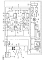
- FIG. 1 an ignition device 10 and a measuring device 12 for determining a state of an electric igniter 14 of a gas turbine burner is shown schematically.
- the ignition device 10 comprises a two opposing electrodes 16 having igniter 14, between the electrode tips 20, a spark 22 can be generated by means of a voltage applied to the electrodes 16 ignition voltage.
- the two electrodes 16 are electrically connected to a secondary winding of an ignition transformer 24.
- the primary winding of the ignition transformer 24 is connected to a switchable AC voltage source 26, wherein a current measuring transducer 28 is connected as a sensor in series with the ignition transformer 24, by means of which a signal characterizing the primary side ignition current can be detected for further processing.
- a primary-side connection of the ignition transformer is electrically connectable via a switch with the phase L, the other terminal of the primary side of the ignition transformer 24 is connected via the current transmitter 28 to the neutral conductor N.
- the electrodes 16 may be, for example, the electrodes of the igniter of a pilot burner or main burner of a gas turbine, with which a fuel gas, a combustible fuel gas-air mixture or an oil-air mixture can be ignited by the provision of a spark 22.
- both the burner and the electrodes 16 according to the in the European patent application with the application number 06017534.6 (published as EP 1 892 474 A1 ) may be formed.
- the Ignition current characterizing signal is provided at the output 30 of the current measuring 28, as soon as the switch of the AC voltage source 26 is closed.
- the characterizing signal can then be supplied to an evaluation unit 29 which mainly comprises three limit detectors 34, 38, 42, three AND gates 50, 57, 53, four timers 48, 60, 72, 80 and an OR gate 54.
- the output 30 of the current measuring transducer 28 is connected to an input 32 of the first limit value detector 34. Furthermore, the output 30 is connected to an input 36 of the second limit indicator 38 and to an input 40 of the third limit indicator 42.
- the output 44 of the first limit indicator 34 is connected to the input 45 of the first AND gate 50, whose output 59 is connected via the input 46 of the timer 48 and the output 50 to the input 52 of the OR gate 54.
- An output 47 of the second limit indicator 38 is connected to an input 67 of the second AND gate 57, whose output 69 is in turn connected via the input 58 of the second timer 60 and the output 62 to an input 64 of the OR gate 54.
- An output 49 of the third limit indicator 42 passes through the third AND gate 53 and the output 66 via the input of the inverter 68 to an input 70 of the third timer 72, whose output 74 is connected to an input 76 of the OR gate 54. Furthermore, the output 66 of the third AND gate 53 is connected to an input 78 of the fourth timer 80, whose output 82 is connected to a fourth input 84 of the OR gate 54.
- the three AND gates 50, 57, 53 ensure as a release interlock that the ignition current to be monitored can be compared with the stored in the memory limits of a reference current (target current average) under the same environmental conditions and can be started at comparable times.
- the method for determining the state of the igniter 14 is started by starting at this point in each limit indicator 34, 38, 42 comparisons are carried out.
- the signal provided by the current transducer 28 at its output 30 representing the primary side firing current is monitored by the first threshold detector 34 in conjunction with the enable latch by the AND gate 50 and the first timer 48.
- At least one upper limit value is stored in the first limit value indicator 34, which is compared with the signal present at its input 32.
- the first limit value represents a maximum permissible current size of the ignition current.
- the output 44 of the first limit value detector 34 indicates a logic "1" signal, which is passed through the AND gate 50 from the first timer 48 to its output 50, provided that the logical " 1 "signal for a minimum period of time, for example 3 seconds continuously applied to the input 46 of the first timer 48.
- the second limit indicator 38, the second AND gate 57 and the second timer 60 operate in an analogous manner, but with the signal applied to the input 36 of the second limit indicator 38, the ignition current characterizing signal stored in the second limit indicator 38 second limit wherein the second threshold detector 38 provides a logic "1" signal at its output 47 as soon as the characterizing signal is below the second threshold.
- the second limit value represents a minimum permissible size of the ignition current.
- the logic "1" signal provided by the output 47 is passed to the OR gate 54, if this for a minimum period, for example 3 seconds at the input 58 of the second timer 60th pending continuously.
- the third threshold detector 42 operates in conjunction with the third AND gate 53, the inverter 68 and the third and fourth timers 72, 80 in a likewise analogous manner.
- the output 74 of the third timer 72 and the output 82 of the fourth timer 80 each carry a logic "0" signal when the characterizing signal at the input 40 of the third threshold detector 42 is not more than a minimum duration, for example three seconds, continuously above or below a third limit value stored in the third limit indicator 42 is present.
- the third limit value corresponds to the setpoint mean value, which lies centrally between the upper and lower limit values.
- the signal present at the input 40 must therefore fluctuate around the third limit, so that the outputs 74, 82 of the third and fourth timers 72, 80 always carry a logic "0" signal. If the current variation fluctuating around the third limit value lasts for more than three seconds, one of the two timers 72, 80 outputs a logic "1" signal.
- the state of the igniter 14 can be detected, wherein upon output of a logic "1" signal, the state of the igniter 14 is defined as non-functional and upon output of a logic "0" signal, the state as functional.
- the limit values stored in the three limit value reports 34, 38 and 42 can be time-dependent, the limit value stored in the first limit value detector 34 forming the upper limit value of a setpoint current envelope, the limit value stored in the second limit value indicator 38 forming the lower limit value of the setpoint current envelope and the third limit value stored in the third limit value indicator 42 then represents the nominal current average value by which the starting current usually fluctuates, provided that a functioning igniter 14 is present and the ignition voltage at the electrode tips 20 generates a sparking spark 22.
- the first and second limit value detectors 34, 38 are each designed as a limit value comparator and the third limit value detector 42 as a comparator, which monitors the signal present at its input 40 and characterizing the current characteristic of the ignition current to a fluctuating characteristic.
- FIG. 2 is an exemplary current waveform represented by a functional igniter 14 of the burner of a gas turbine. Accordingly, a time is plotted on the abscissa, while the ignition current or the magnitude of the signal characterizing this is plotted on the ordinate.
- FIG. 2 the actual current profile detected by the current measuring transducer 28 is shown in a line 43.
- the current waveform 43 shown here reflects an example of a current profile that occurs when the igniters 14 are functioning.
- the current profile was determined at a particularly low rotor speed, for example 2 Hz, which occurs before the start.
- the value of 2 Hz corresponds to a rotor speed of 120 revolutions per minute. Due to the comparatively low rotor speed of the gas turbine, the compressor associated with the gas turbine sucks in a comparatively small amount of air, as a result of which the air pumped through the burners and through the turbine has no appreciable influence on an ignition spark 22 arranged at the tip 20 of the electrodes 16 is. If the method according to the invention is carried out at such a low rotor speed, it is possible to work with time-constant limit values.
- the procedure provides for the use of three limit values.
- the first limit value which may also be referred to as the upper limit value, represents the maximum permissible ignition current of the igniter 14.
- the upper limit value characteristic is in FIG. 2 shown in a dash-dotted line style and provided with the reference numeral 31.
- the upper limit value characteristic 31 according to FIG. 2 shows a temporally constant limit value, which can be stored in the first limit indicator 34.
- the second limit which may also be referred to as the lower limit, is shown in dashed line style.
- the according to FIG. 2 temporally constant limit value is represented by means of a lower limit characteristic curve 41.
- the upper limit value 31 and the lower limit value 41 form a setpoint current envelope or interval in which the actual occurring ignition current must lie at a functional igniter 14 at a low rotor speed.
- the third limit value, which is also constant in time, which represents the nominal current mean value, is in FIG. 2 shown in dotted line 51.
- the ignition current and its characterizing signal fluctuate around the third limit value 51, which lies centrally between the upper and lower limit values 31, 41. If the randomly around the third threshold 51 fluctuating current waveform 43 of the ignition current does not occur, this indicates a non-functional igniter 14.
- FIG. 3 shows you one FIG. 2 analogous diagram in which the time on the abscissa and on the ordinate of the ignition current is discharged.
- the first, now time-dependent upper limit value 31 is shown.
- 41 the second, also time-dependent limit value is shown, which represents a lower allowable limit for the ignition current as a function of time.
- the time-dependent upper limit value 31 and time-dependent lower limit value 41 form an envelope curve for the nominal current, in which the actual occurring, but in its size random ignition current can vary, provided that the fuze 14 is functional.
- a further improved method for monitoring the igniter 14 can be indicated with the aid of now time-dependent limit values. Due to the steady increases in the rotor speed of the rotor, which is driven by an external rotary device, the amount of air sucked in by the compressor is steadily increased. The amount of air sucked in by the compressor is also partly conducted past the igniters 14 of the gas turbine burner, so that the ambient conditions of the spark also change steadily as the amount of air passed by. Due to the change in the environmental conditions of the spark 22, its ignition current also changes.
- the limit values 31, 41, 51 on which the method is based are stored as time-dependent variables in the limit value detectors 34, 38, 42 and based on the comparisons carried out continuously therein. Again, the comparisons are performed from the time from which the ignition voltage is applied to the ignition transformer 24 with the switch of the switchable AC voltage source 26.
- the determination of the limit values 31, 41 and 51 for example, after switching off the gas turbine, take place at a corresponding rotor speed. For this purpose, one or more times a test ignition is performed during the startup of the gas turbine, in which all fuel valves remain closed and thus exits from the fuel exits no combustible mixture or fuel. For the duration of the test ignition of the Zündstromverlauf is determined, from which by means of an interpolation using a third degree polynomial a desired current trend characteristic can be determined. By determining several such desired current trend characteristics and by their averaging further random influences can be excluded.
- the upper limit value or the upper limit value characteristic 31 and the lower limit value or the lower limit value characteristic 41 can then be converted by simple parallel displacement, i. H. by addition or subtraction of a permissible current deviation of the ignition current.
- a pattern comparison of current waveforms may also be performed to determine whether the igniter 14 monitored by the meter 12 is functional or not.
- the measuring device 12 can have, as an alternative to the evaluation unit 29 or in addition thereto, a device 13 for pattern monitoring.
- the ignition current characterizing signal of the current measuring 30 is a Input 61 of a writable value memory 63 can be fed.
- a multiplier element 65 the current values stored in the value memory 63 or the values representing the determined current profile can be multiplied by a factor F, if a later comparison of the stored values with an actual current profile is to be carried out, which at a rotor speed other than that at the values stored in value memory have been determined.
- the ignition current is determined after switching off a gas turbine (coasting operation).
- the ignition transformer 24 is then turned on at a constant rotor speed of 2 Hz once it is reached for ten seconds. Meanwhile, the ignition current is continuously detected and stored its history as time-dependent values in the value memory 63. In the meantime, to store the values present at input X1, a logic "1" signal is present at input I1 of value memory 63.
- the pattern comparison can be carried out in particular after an off-line compressor wash.
- a difference magnitude is provided at the output 95 of the subtraction point 94 which varies about a zero point when the actual firing current history and stored firing current history are similar, indicating a functioning igniter 14.
- Deviations from the zero line can be determined with the aid of a fourth limit indicator 96, an inverter 97, a fifth timer 98 and a sixth timer 99. If the deviations unilaterally pending longer than a predetermined period of time, so by an OR gate 100 by issuing a logic "1" signal, the state of the igniter 14 is reported as non-functional.
- the start release of the gas turbine which is equivalent to opening the fuel valves, be denied if it is determined after a wash program that so many detonators 14 are affected by moisture in their function that a false start of the gas turbine is likely. If this fault is detected by means of ignition devices 10, the start of the gas turbine can be shifted. Then, the ignition electrodes 16 can be dried by preheating. The preheating can be achieved for example by switching on the ignition transformer 24 for a period of about 30 seconds.
- the drying of the still probable wet igniter can be initiated. If in a subsequent, re-test ignition resp. If a sufficient number of operational igniters, such as 75% of the number of igniters, is detected by the test measurement, the gas turbine can be started without the risk of igniter ignition misfires.
- the invention provides a method for determining a condition of an electric igniter 14 of a gas turbine burner and a measuring device 12 and an igniter 10 for a gas turbine burner can be avoided by means of the false starts of gas turbines due to non-functional igniter.
- the method provides for comparing a time-dependent signal characterizing the ignition current of a fuse 14 with an upper limit value and a lower limit value and at the same time comparing the characterizing signal to a desired current average value by which the ignition current is to randomly fluctuate when the fuze 14 is functioning ,
Landscapes
- Engineering & Computer Science (AREA)
- Combustion & Propulsion (AREA)
- Chemical & Material Sciences (AREA)
- Physics & Mathematics (AREA)
- General Physics & Mathematics (AREA)
- General Engineering & Computer Science (AREA)
- Artificial Intelligence (AREA)
- Computer Vision & Pattern Recognition (AREA)
- Evolutionary Computation (AREA)
- Medical Informatics (AREA)
- Software Systems (AREA)
- Health & Medical Sciences (AREA)
- Mechanical Engineering (AREA)
- Automation & Control Theory (AREA)
- Regulation And Control Of Combustion (AREA)
- Other Investigation Or Analysis Of Materials By Electrical Means (AREA)
- Control Of Turbines (AREA)
Claims (14)
- Procédé de détermination d'un état d'un allumeur ( 14 ) électrique d'un brûleur de turbine à gaz, dans lequel, dans un premier stade, un signal, dépendant du temps et caractérisant le courant d'allumage d'un allumeur ( 14 ), a une valeur limite supérieure et une valeur limite inférieure,
caractérisé en ce que
le signal caractérisant décrit la valeur du courant d'allumage et
dans un autre stade, on compare le signal caractérisant à une valeur moyenne de courant de consigne, la valeur limite supérieure et la valeur limite inférieure avec formation d'une courbe enveloppe de courant de consigne et/ou la valeur moyenne du courant de consigne avec formation d'une courbe ( 51 ) caractéristique, vers laquelle tend le courant de consigne, dépendant respectivement du temps. - Procédé suivant la revendication 1,
dans lequel on détermine l'état de l'allumeur ( 14 ) comme étant inapte à fonctionner, si le signal caractérisant se trouve pendant une première durée minimum à l'extérieur de l'intervalle formé par la valeur limite supérieure et par la valeur limite inférieure. - Procédé suivant la revendication 1 ou 2,
dans lequel on détermine l'état de l'allumeur ( 14 ) comme inapte à fonctionner, si le signal caractérisant ne fluctue pas pendant une deuxième durée minimum autour de la valeur moyenne de courant de consigne ou respectivement de la courbe ( 51 ) caractéristique, vers laquelle tend le courant de consigne. - Procédé suivant l'une des revendications précédentes,
dans lequel il est prévu un transformateur ( 24 ) d'allumage pour la production d'une tension d'allumage d'électrodes ( 16 ) d'allumage, le courant du côté primaire du transformateur ( 24 ) d'allumage étant détecté en tant que courant d'allumage. - Procédé suivant l'une des revendications précédentes,
dans lequel on effectue les comparaisons au moyen de plusieurs comparaisons de modèles de courbes de courant. - Procédé suivant l'une des revendications précédentes, qui s'effectue pendant la rotation d'un rotor d'une turbine à gaz ou avant le démarrage de la turbine à gaz.
- Procédé suivant la revendication 6,
dans lequel la vitesse de rotation du rotor se modifie. - Procédé suivant l'une des revendications précédentes,
dans lequel on détermine auparavant la courbe de courant d'un allumage ( 14 ) apte à fonctionner,
à partir de laquelle on détermine la courbe ( 51 ) caractéristique, vers laquelle tend le courant de consigne. - Procédé suivant la revendication 8,
caractérisé en ce qu'on détecte la courbe de courant de l'allumeur ( 14 ) apte à fonctionner après l'arrêt de la turbine à gaz. - Procédé suivant l'une des revendications précédentes,
dans lequel, dans un autre stade, on détermine un nombre d'allumeurs aptes à fonctionner du brûleur de la turbine à gaz et on compare ce nombre à un nombre minimum donné à l'avance de brûleurs aptes à fonctionner
dans lequel, si un nombre minimum de brûleurs, lequel est plus petit que le nombre des allumeurs ou brûleurs, est reconnu comme apte à fonctionner, dans un stade venant ensuite dans le temps, on ouvre l'apport de combustible au nombre de brûleurs de la turbine à gaz. - Dispositif ( 12 ) de mesure pour la détermination d'un état d'un allumeur ( 14 ) électrique d'un brûleur de turbine à gaz
comprenant
un capteur ( 28 ) pour la détection avec résolution dans le temps du courant d'un allumeur ( 14 ) électrique d'un brûleur de turbine à gaz
et un dispositif ( 29 ) d'exploitation, couplé au capteur ( 28 ) et ayant au moins une mémoire et au moins un moyen de comparaison du signal fourni par le capteur ( 28 ) à au moins une valeur limite mémorisée dans la mémoire, dans lequel, il est mémorisé, dans le dispositif ( 29 ) d'exploitation, trois valeurs différentes dans leur dimension et trois moyens de comparaison du signal à respectivement l'une des trois valeurs,
caractérisé en ce que
deux des trois valeurs forment, en tant que valeurs limites qui dépendent du temps, une courbe ( 31, 41 ) enveloppe et deux des trois moyens sont conformés en comparateurs de valeur limite et dans lequel l'une des trois valeurs est conformée en courbe ( 51 ) caractéristique qui dépend du temps et vers laquelle tend le courant de consigne et l'un des trois moyens est constitué en comparateur qui contrôle la fluctuation du signal autour de la courbe caractéristique, vers laquelle tend le courant de consigne. - Dispositif ( 12 ) de mesure suivant la revendication 11, dans lequel la courbe ( 31, 41 ) enveloppe et/ou la courbe ( 51 ) caractéristique, vers laquelle tend le courant de consigne est ou sont mémorisés sous la forme d'une courbe caractéristique ou sous la forme d'une table.
- Dispositif ( 10 ) d'allumage d'un brûleur d'une turbine à gaz,
comprenant
un allumeur ( 14 ) ayant deux électrodes ( 16 ) opposées l'une à l'autre, entre les pointes ( 20 ) d'électrodes desquelles une étincelle ( 22 ) d'allumage peut être produite au moyen d'une tension d'allumage et
un transformateur ( 24 ) d'allumage pour la production de la tension d'allumage, lequel transformateur ( 24 ) d'allumage est relié électriquement du côté secondaire aux électrodes ( 16 ),
caractérisé en ce que
le dispositif ( 10 ) d'allumage comprend un dispositif ( 12 ) de mesure pour la détermination d'un état d'un allumeur ( 14 ) électrique d'un brûleur de turbine à gaz suivant l'une des revendications 11 à 12. - Dispositif ( 10 ) d'allumage suivant la revendication 13, dans lequel le capteur ( 28 ) du dispositif ( 12 ) de mesure est monté du côté primaire sur le transformateur ( 24 ) d'allumage.
Applications Claiming Priority (2)
| Application Number | Priority Date | Filing Date | Title |
|---|---|---|---|
| DE102008058571 | 2008-11-21 | ||
| PCT/EP2009/050578 WO2010057680A1 (fr) | 2008-11-21 | 2009-01-20 | Procédé et dispositif de mesure pour déterminer un état d'un allumeur électrique d'un brûleur de turbine à gaz, ainsi que dispositif d'allumage pour un brûleur de turbine à gaz |
Publications (2)
| Publication Number | Publication Date |
|---|---|
| EP2387737A1 EP2387737A1 (fr) | 2011-11-23 |
| EP2387737B1 true EP2387737B1 (fr) | 2014-06-25 |
Family
ID=40973559
Family Applications (1)
| Application Number | Title | Priority Date | Filing Date |
|---|---|---|---|
| EP09778965.5A Active EP2387737B1 (fr) | 2008-11-21 | 2009-01-20 | Procédé et dispositif de mesure pour déterminer un état d'un allumeur électrique d'un brûleur de turbine à gaz, ainsi que dispositif d'allumage pour un brûleur de turbine à gaz |
Country Status (6)
| Country | Link |
|---|---|
| US (1) | US8564276B2 (fr) |
| EP (1) | EP2387737B1 (fr) |
| CN (1) | CN102224468B (fr) |
| ES (1) | ES2496182T3 (fr) |
| RU (1) | RU2477509C2 (fr) |
| WO (1) | WO2010057680A1 (fr) |
Families Citing this family (9)
| Publication number | Priority date | Publication date | Assignee | Title |
|---|---|---|---|---|
| FR2960913B1 (fr) * | 2010-06-04 | 2012-07-13 | Snecma | Prechauffage d'une bougie d'allumage |
| US20120125007A1 (en) * | 2010-11-22 | 2012-05-24 | Joseph Bernard Steffler | Method and system for engine ignition and monitoring |
| US9429075B2 (en) * | 2013-01-31 | 2016-08-30 | General Electric Company | Method of operating a fuel heating system |
| US9984699B2 (en) | 2014-06-26 | 2018-05-29 | Qualcomm Incorporated | High-band signal coding using mismatched frequency ranges |
| JP6173367B2 (ja) | 2015-02-03 | 2017-08-02 | 三菱日立パワーシステムズ株式会社 | 状態判定装置、運転制御装置、ガスタービン及び状態判定方法 |
| US12031513B2 (en) * | 2020-11-18 | 2024-07-09 | Pratt & Whitney Canada Corp. | Method and system for glow plug operation |
| US11739693B2 (en) | 2020-11-18 | 2023-08-29 | Pratt & Whitney Canada Corp. | Method and system for glow plug operation |
| CN113374582B (zh) * | 2021-07-28 | 2022-09-27 | 哈电发电设备国家工程研究中心有限公司 | 一种燃气轮机运行状态评估装置及方法 |
| CN117091156B (zh) * | 2023-07-31 | 2025-10-14 | 中国船舶集团有限公司第七一三研究所 | 一种基于霍尔效应点火结果的判定方法和装置 |
Family Cites Families (9)
| Publication number | Priority date | Publication date | Assignee | Title |
|---|---|---|---|---|
| GB8529223D0 (en) * | 1985-11-27 | 1986-01-02 | Lucas Ind Plc | Monitoring gas turbine engine |
| US5116764A (en) * | 1988-07-26 | 1992-05-26 | Raymond Annino | Dual-column, dual-detector gas detector and analyzer |
| DE19524499B4 (de) * | 1995-07-05 | 2008-11-13 | Robert Bosch Gmbh | Zündanlage für eine Brennkraftmaschine |
| KR100189408B1 (ko) * | 1995-11-20 | 1999-06-01 | 이건수 | 연소기기의 연소상태검출회로 |
| US6006156A (en) * | 1997-12-11 | 1999-12-21 | Cummins Engine Company, Inc. | Apparatus and method for diagnosing and controlling an ignition system of an internal combustion engine |
| US6761156B2 (en) * | 2002-02-20 | 2004-07-13 | Daimlerchrysler Corporation | Multiplexed single wire control and diagnosis of an electrical object |
| DE10305928B3 (de) * | 2003-02-13 | 2004-10-07 | Mertik Maxitrol Gmbh & Co. Kg | Verfahren und Schaltungsanordnung zum Zünden eines Gasstromes |
| DE102006005711A1 (de) | 2006-02-08 | 2007-08-23 | Robert Bosch Gmbh | Verfahren und Vorrichtung zur Überwachung wenigstens einer Glühkerze eines Kraftfahrzeugs |
| EP1892474A1 (fr) | 2006-08-23 | 2008-02-27 | Siemens Aktiengesellschaft | Brûleur avec élément de protection pour électrodes d'allumage |
-
2009
- 2009-01-20 EP EP09778965.5A patent/EP2387737B1/fr active Active
- 2009-01-20 RU RU2011125324/08A patent/RU2477509C2/ru active
- 2009-01-20 US US13/130,107 patent/US8564276B2/en active Active
- 2009-01-20 WO PCT/EP2009/050578 patent/WO2010057680A1/fr not_active Ceased
- 2009-01-20 CN CN200980146628.XA patent/CN102224468B/zh active Active
- 2009-01-20 ES ES09778965.5T patent/ES2496182T3/es active Active
Also Published As
| Publication number | Publication date |
|---|---|
| CN102224468B (zh) | 2014-02-12 |
| WO2010057680A1 (fr) | 2010-05-27 |
| ES2496182T3 (es) | 2014-09-18 |
| EP2387737A1 (fr) | 2011-11-23 |
| CN102224468A (zh) | 2011-10-19 |
| US20110221422A1 (en) | 2011-09-15 |
| RU2011125324A (ru) | 2012-12-27 |
| RU2477509C2 (ru) | 2013-03-10 |
| US8564276B2 (en) | 2013-10-22 |
Similar Documents
| Publication | Publication Date | Title |
|---|---|---|
| EP2387737B1 (fr) | Procédé et dispositif de mesure pour déterminer un état d'un allumeur électrique d'un brûleur de turbine à gaz, ainsi que dispositif d'allumage pour un brûleur de turbine à gaz | |
| EP3919817B1 (fr) | Procédé et dispositif de détection des défauts d'allumage d'un brûleur avec un ventilateur pour l'alimentation en air et une soupape à combustible | |
| DE102016118432A1 (de) | Verfahren und System zum Überwachen eines Zündzustands in einem Gasturbinenmotor | |
| DE102011087599A1 (de) | Druckmessvorrichtung und Druckmessverfahren für eine Strömungskraftmaschine | |
| EP3581850B1 (fr) | Procédé de fonctionnement d'un brûleur | |
| EP1719947A1 (fr) | Procédé et dispositif de contrôle de flammes | |
| DE19733355C2 (de) | Verbrennungszustands-Erfassungsvorrichtung für einen Verbrennungsmotor | |
| DE19838334B4 (de) | Diagnoseeinrichtung für eine potentiometrische, elektrisch beheizte Abgassonde zur Regelung von Verbrennungsprozessen | |
| DE102008045367B4 (de) | Verbrennungsmotor-Zünddiagnosevorrichtung und Verbrennungsmotor-Steuervorrichtung | |
| DE4132858C2 (de) | Steuervorrichtung mit Feldzündungsdetektion für eine Brennkraftmaschine | |
| EP1021684A1 (fr) | Procede et dispositif pour la surveillance d'une flamme | |
| EP3882519A1 (fr) | Procédé de fonctionnement d'un dispositif brûleur | |
| EP1554475A1 (fr) | Procede et systeme pour controler le bon fonctionnement d'un detecteur de particules | |
| EP1843645B1 (fr) | Circuit pour lampes à décharge haute pression | |
| EP2256326B1 (fr) | Procédé et dispositif de détection d'une formation d'étincelle défectueuse dans un moteur à combustion interne à allumage commandé doté d'un ou plusieurs cylindres | |
| DE102011010074B4 (de) | Verfahren zur Überprüfung der Funktionstüchtigkeit eines Sensors und zur Regelung einer Feuerungsanlage | |
| DE102010045173B4 (de) | Verfahren zum Überprüfen des Zustandes eines in eine Brennkammer eines Verbrennungsmotors eingebauten Zünders | |
| DE102021100119A1 (de) | Verfahren und Anordnung zur Erkennung von Flüssigkeit in einem Gebläse eines Heizgerätes | |
| EP0845637B1 (fr) | Procédé de surveillance de la flamme dans un appareil de chauffage utilisant un combustible | |
| DE102020203996B4 (de) | Verfahren zum Ermitteln einer Funkenbrenndauer beim Betrieb einer Zündvorrichtung | |
| DE10133005B4 (de) | Verfahren und Vorrichtung zum Erkennen der Unterbrechung der Spannungsversorgung einer Zündspule | |
| EP3106753B1 (fr) | Surveillance de flammes | |
| DE19625823C2 (de) | Verfahren zur Flammüberwachung für ein Fahrzeugheizgerät | |
| DE102005030481B4 (de) | Verfahren zum Zünden eines Brennstoff-Luftgemisches | |
| EP1209417B1 (fr) | Procédé de fonctionnement pour un brûleur à gaz |
Legal Events
| Date | Code | Title | Description |
|---|---|---|---|
| PUAI | Public reference made under article 153(3) epc to a published international application that has entered the european phase |
Free format text: ORIGINAL CODE: 0009012 |
|
| 17P | Request for examination filed |
Effective date: 20110426 |
|
| AK | Designated contracting states |
Kind code of ref document: A1 Designated state(s): AT BE BG CH CY CZ DE DK EE ES FI FR GB GR HR HU IE IS IT LI LT LU LV MC MK MT NL NO PL PT RO SE SI SK TR |
|
| DAX | Request for extension of the european patent (deleted) | ||
| RAP1 | Party data changed (applicant data changed or rights of an application transferred) |
Owner name: SIEMENS AKTIENGESELLSCHAFT |
|
| REG | Reference to a national code |
Ref country code: DE Ref legal event code: R079 Ref document number: 502009009582 Country of ref document: DE Free format text: PREVIOUS MAIN CLASS: G05B0013020000 Ipc: F02C0007266000 |
|
| GRAP | Despatch of communication of intention to grant a patent |
Free format text: ORIGINAL CODE: EPIDOSNIGR1 |
|
| RIC1 | Information provided on ipc code assigned before grant |
Ipc: F02C 7/266 20060101AFI20140114BHEP Ipc: G05B 13/02 20060101ALI20140114BHEP Ipc: G01R 19/00 20060101ALI20140114BHEP Ipc: F02P 17/12 20060101ALI20140114BHEP |
|
| INTG | Intention to grant announced |
Effective date: 20140130 |
|
| GRAS | Grant fee paid |
Free format text: ORIGINAL CODE: EPIDOSNIGR3 |
|
| GRAA | (expected) grant |
Free format text: ORIGINAL CODE: 0009210 |
|
| AK | Designated contracting states |
Kind code of ref document: B1 Designated state(s): AT BE BG CH CY CZ DE DK EE ES FI FR GB GR HR HU IE IS IT LI LT LU LV MC MK MT NL NO PL PT RO SE SI SK TR |
|
| REG | Reference to a national code |
Ref country code: GB Ref legal event code: FG4D Free format text: NOT ENGLISH |
|
| REG | Reference to a national code |
Ref country code: CH Ref legal event code: EP |
|
| REG | Reference to a national code |
Ref country code: CH Ref legal event code: NV Representative=s name: SIEMENS SCHWEIZ AG, CH Ref country code: AT Ref legal event code: REF Ref document number: 674867 Country of ref document: AT Kind code of ref document: T Effective date: 20140715 |
|
| REG | Reference to a national code |
Ref country code: IE Ref legal event code: FG4D Free format text: LANGUAGE OF EP DOCUMENT: GERMAN |
|
| REG | Reference to a national code |
Ref country code: DE Ref legal event code: R096 Ref document number: 502009009582 Country of ref document: DE Effective date: 20140807 |
|
| REG | Reference to a national code |
Ref country code: ES Ref legal event code: FG2A Ref document number: 2496182 Country of ref document: ES Kind code of ref document: T3 Effective date: 20140918 |
|
| REG | Reference to a national code |
Ref country code: SE Ref legal event code: TRGR |
|
| PG25 | Lapsed in a contracting state [announced via postgrant information from national office to epo] |
Ref country code: GR Free format text: LAPSE BECAUSE OF FAILURE TO SUBMIT A TRANSLATION OF THE DESCRIPTION OR TO PAY THE FEE WITHIN THE PRESCRIBED TIME-LIMIT Effective date: 20140926 Ref country code: CY Free format text: LAPSE BECAUSE OF FAILURE TO SUBMIT A TRANSLATION OF THE DESCRIPTION OR TO PAY THE FEE WITHIN THE PRESCRIBED TIME-LIMIT Effective date: 20140625 Ref country code: FI Free format text: LAPSE BECAUSE OF FAILURE TO SUBMIT A TRANSLATION OF THE DESCRIPTION OR TO PAY THE FEE WITHIN THE PRESCRIBED TIME-LIMIT Effective date: 20140625 Ref country code: NO Free format text: LAPSE BECAUSE OF FAILURE TO SUBMIT A TRANSLATION OF THE DESCRIPTION OR TO PAY THE FEE WITHIN THE PRESCRIBED TIME-LIMIT Effective date: 20140925 Ref country code: LT Free format text: LAPSE BECAUSE OF FAILURE TO SUBMIT A TRANSLATION OF THE DESCRIPTION OR TO PAY THE FEE WITHIN THE PRESCRIBED TIME-LIMIT Effective date: 20140625 |
|
| REG | Reference to a national code |
Ref country code: NL Ref legal event code: VDEP Effective date: 20140625 |
|
| REG | Reference to a national code |
Ref country code: LT Ref legal event code: MG4D |
|
| PG25 | Lapsed in a contracting state [announced via postgrant information from national office to epo] |
Ref country code: LV Free format text: LAPSE BECAUSE OF FAILURE TO SUBMIT A TRANSLATION OF THE DESCRIPTION OR TO PAY THE FEE WITHIN THE PRESCRIBED TIME-LIMIT Effective date: 20140625 Ref country code: HR Free format text: LAPSE BECAUSE OF FAILURE TO SUBMIT A TRANSLATION OF THE DESCRIPTION OR TO PAY THE FEE WITHIN THE PRESCRIBED TIME-LIMIT Effective date: 20140625 |
|
| PG25 | Lapsed in a contracting state [announced via postgrant information from national office to epo] |
Ref country code: EE Free format text: LAPSE BECAUSE OF FAILURE TO SUBMIT A TRANSLATION OF THE DESCRIPTION OR TO PAY THE FEE WITHIN THE PRESCRIBED TIME-LIMIT Effective date: 20140625 Ref country code: PT Free format text: LAPSE BECAUSE OF FAILURE TO SUBMIT A TRANSLATION OF THE DESCRIPTION OR TO PAY THE FEE WITHIN THE PRESCRIBED TIME-LIMIT Effective date: 20141027 Ref country code: RO Free format text: LAPSE BECAUSE OF FAILURE TO SUBMIT A TRANSLATION OF THE DESCRIPTION OR TO PAY THE FEE WITHIN THE PRESCRIBED TIME-LIMIT Effective date: 20140625 Ref country code: SK Free format text: LAPSE BECAUSE OF FAILURE TO SUBMIT A TRANSLATION OF THE DESCRIPTION OR TO PAY THE FEE WITHIN THE PRESCRIBED TIME-LIMIT Effective date: 20140625 Ref country code: CZ Free format text: LAPSE BECAUSE OF FAILURE TO SUBMIT A TRANSLATION OF THE DESCRIPTION OR TO PAY THE FEE WITHIN THE PRESCRIBED TIME-LIMIT Effective date: 20140625 |
|
| PG25 | Lapsed in a contracting state [announced via postgrant information from national office to epo] |
Ref country code: NL Free format text: LAPSE BECAUSE OF FAILURE TO SUBMIT A TRANSLATION OF THE DESCRIPTION OR TO PAY THE FEE WITHIN THE PRESCRIBED TIME-LIMIT Effective date: 20140625 Ref country code: IS Free format text: LAPSE BECAUSE OF FAILURE TO SUBMIT A TRANSLATION OF THE DESCRIPTION OR TO PAY THE FEE WITHIN THE PRESCRIBED TIME-LIMIT Effective date: 20141025 Ref country code: PL Free format text: LAPSE BECAUSE OF FAILURE TO SUBMIT A TRANSLATION OF THE DESCRIPTION OR TO PAY THE FEE WITHIN THE PRESCRIBED TIME-LIMIT Effective date: 20140625 |
|
| REG | Reference to a national code |
Ref country code: DE Ref legal event code: R097 Ref document number: 502009009582 Country of ref document: DE |
|
| PG25 | Lapsed in a contracting state [announced via postgrant information from national office to epo] |
Ref country code: DK Free format text: LAPSE BECAUSE OF FAILURE TO SUBMIT A TRANSLATION OF THE DESCRIPTION OR TO PAY THE FEE WITHIN THE PRESCRIBED TIME-LIMIT Effective date: 20140625 |
|
| PLBE | No opposition filed within time limit |
Free format text: ORIGINAL CODE: 0009261 |
|
| STAA | Information on the status of an ep patent application or granted ep patent |
Free format text: STATUS: NO OPPOSITION FILED WITHIN TIME LIMIT |
|
| 26N | No opposition filed |
Effective date: 20150326 |
|
| PG25 | Lapsed in a contracting state [announced via postgrant information from national office to epo] |
Ref country code: BE Free format text: LAPSE BECAUSE OF NON-PAYMENT OF DUE FEES Effective date: 20150131 |
|
| PG25 | Lapsed in a contracting state [announced via postgrant information from national office to epo] |
Ref country code: LU Free format text: LAPSE BECAUSE OF FAILURE TO SUBMIT A TRANSLATION OF THE DESCRIPTION OR TO PAY THE FEE WITHIN THE PRESCRIBED TIME-LIMIT Effective date: 20150120 |
|
| PG25 | Lapsed in a contracting state [announced via postgrant information from national office to epo] |
Ref country code: MC Free format text: LAPSE BECAUSE OF FAILURE TO SUBMIT A TRANSLATION OF THE DESCRIPTION OR TO PAY THE FEE WITHIN THE PRESCRIBED TIME-LIMIT Effective date: 20140625 |
|
| REG | Reference to a national code |
Ref country code: IE Ref legal event code: MM4A |
|
| PG25 | Lapsed in a contracting state [announced via postgrant information from national office to epo] |
Ref country code: SI Free format text: LAPSE BECAUSE OF FAILURE TO SUBMIT A TRANSLATION OF THE DESCRIPTION OR TO PAY THE FEE WITHIN THE PRESCRIBED TIME-LIMIT Effective date: 20140625 |
|
| REG | Reference to a national code |
Ref country code: FR Ref legal event code: PLFP Year of fee payment: 8 |
|
| PG25 | Lapsed in a contracting state [announced via postgrant information from national office to epo] |
Ref country code: IE Free format text: LAPSE BECAUSE OF NON-PAYMENT OF DUE FEES Effective date: 20150120 |
|
| REG | Reference to a national code |
Ref country code: AT Ref legal event code: MM01 Ref document number: 674867 Country of ref document: AT Kind code of ref document: T Effective date: 20150120 |
|
| PG25 | Lapsed in a contracting state [announced via postgrant information from national office to epo] |
Ref country code: AT Free format text: LAPSE BECAUSE OF NON-PAYMENT OF DUE FEES Effective date: 20150120 |
|
| PG25 | Lapsed in a contracting state [announced via postgrant information from national office to epo] |
Ref country code: MT Free format text: LAPSE BECAUSE OF FAILURE TO SUBMIT A TRANSLATION OF THE DESCRIPTION OR TO PAY THE FEE WITHIN THE PRESCRIBED TIME-LIMIT Effective date: 20140625 |
|
| REG | Reference to a national code |
Ref country code: FR Ref legal event code: PLFP Year of fee payment: 9 |
|
| PG25 | Lapsed in a contracting state [announced via postgrant information from national office to epo] |
Ref country code: HU Free format text: LAPSE BECAUSE OF FAILURE TO SUBMIT A TRANSLATION OF THE DESCRIPTION OR TO PAY THE FEE WITHIN THE PRESCRIBED TIME-LIMIT; INVALID AB INITIO Effective date: 20090120 Ref country code: BG Free format text: LAPSE BECAUSE OF FAILURE TO SUBMIT A TRANSLATION OF THE DESCRIPTION OR TO PAY THE FEE WITHIN THE PRESCRIBED TIME-LIMIT Effective date: 20140625 |
|
| PG25 | Lapsed in a contracting state [announced via postgrant information from national office to epo] |
Ref country code: TR Free format text: LAPSE BECAUSE OF FAILURE TO SUBMIT A TRANSLATION OF THE DESCRIPTION OR TO PAY THE FEE WITHIN THE PRESCRIBED TIME-LIMIT Effective date: 20140625 |
|
| REG | Reference to a national code |
Ref country code: CH Ref legal event code: PCOW Free format text: NEW ADDRESS: WERNER-VON-SIEMENS-STRASSE 1, 80333 MUENCHEN (DE) |
|
| REG | Reference to a national code |
Ref country code: FR Ref legal event code: PLFP Year of fee payment: 10 |
|
| PG25 | Lapsed in a contracting state [announced via postgrant information from national office to epo] |
Ref country code: MK Free format text: LAPSE BECAUSE OF FAILURE TO SUBMIT A TRANSLATION OF THE DESCRIPTION OR TO PAY THE FEE WITHIN THE PRESCRIBED TIME-LIMIT Effective date: 20140625 |
|
| PGFP | Annual fee paid to national office [announced via postgrant information from national office to epo] |
Ref country code: ES Payment date: 20190422 Year of fee payment: 11 |
|
| REG | Reference to a national code |
Ref country code: DE Ref legal event code: R081 Ref document number: 502009009582 Country of ref document: DE Owner name: SIEMENS ENERGY GLOBAL GMBH & CO. KG, DE Free format text: FORMER OWNER: SIEMENS AG, 80333 MUENCHEN, DE |
|
| PG25 | Lapsed in a contracting state [announced via postgrant information from national office to epo] |
Ref country code: ES Free format text: LAPSE BECAUSE OF NON-PAYMENT OF DUE FEES Effective date: 20200121 |
|
| REG | Reference to a national code |
Ref country code: GB Ref legal event code: 732E Free format text: REGISTERED BETWEEN 20220818 AND 20220824 |
|
| PGFP | Annual fee paid to national office [announced via postgrant information from national office to epo] |
Ref country code: CH Payment date: 20250201 Year of fee payment: 17 |
|
| REG | Reference to a national code |
Ref country code: CH Ref legal event code: U11 Free format text: ST27 STATUS EVENT CODE: U-0-0-U10-U11 (AS PROVIDED BY THE NATIONAL OFFICE) Effective date: 20260201 |
|
| PGFP | Annual fee paid to national office [announced via postgrant information from national office to epo] |
Ref country code: SE Payment date: 20260126 Year of fee payment: 18 |
|
| PGFP | Annual fee paid to national office [announced via postgrant information from national office to epo] |
Ref country code: GB Payment date: 20260126 Year of fee payment: 18 |
|
| PGFP | Annual fee paid to national office [announced via postgrant information from national office to epo] |
Ref country code: DE Payment date: 20260127 Year of fee payment: 18 |
|
| PGFP | Annual fee paid to national office [announced via postgrant information from national office to epo] |
Ref country code: IT Payment date: 20260123 Year of fee payment: 18 |
|
| PGFP | Annual fee paid to national office [announced via postgrant information from national office to epo] |
Ref country code: FR Payment date: 20260126 Year of fee payment: 18 |