EP2387928A2 - Procédé de fonctionnement dýun aspirateur, ainsi quýaspirateur à moteur électrique et réservoir de matériau de filtre en forme de tuyau - Google Patents
Procédé de fonctionnement dýun aspirateur, ainsi quýaspirateur à moteur électrique et réservoir de matériau de filtre en forme de tuyau Download PDFInfo
- Publication number
- EP2387928A2 EP2387928A2 EP11176242A EP11176242A EP2387928A2 EP 2387928 A2 EP2387928 A2 EP 2387928A2 EP 11176242 A EP11176242 A EP 11176242A EP 11176242 A EP11176242 A EP 11176242A EP 2387928 A2 EP2387928 A2 EP 2387928A2
- Authority
- EP
- European Patent Office
- Prior art keywords
- dust filter
- vacuum cleaner
- filter bag
- filter material
- bag
- Prior art date
- Legal status (The legal status is an assumption and is not a legal conclusion. Google has not performed a legal analysis and makes no representation as to the accuracy of the status listed.)
- Granted
Links
Images











Classifications
-
- A—HUMAN NECESSITIES
- A47—FURNITURE; DOMESTIC ARTICLES OR APPLIANCES; COFFEE MILLS; SPICE MILLS; SUCTION CLEANERS IN GENERAL
- A47L—DOMESTIC WASHING OR CLEANING; SUCTION CLEANERS IN GENERAL
- A47L9/00—Details or accessories of suction cleaners, e.g. mechanical means for controlling the suction or for effecting pulsating action; Storing devices specially adapted to suction cleaners or parts thereof; Carrying-vehicles specially adapted for suction cleaners
- A47L9/10—Filters; Dust separators; Dust removal; Automatic exchange of filters
- A47L9/14—Bags or the like; Rigid filtering receptacles; Attachment of, or closures for, bags or receptacles
-
- A—HUMAN NECESSITIES
- A47—FURNITURE; DOMESTIC ARTICLES OR APPLIANCES; COFFEE MILLS; SPICE MILLS; SUCTION CLEANERS IN GENERAL
- A47L—DOMESTIC WASHING OR CLEANING; SUCTION CLEANERS IN GENERAL
- A47L9/00—Details or accessories of suction cleaners, e.g. mechanical means for controlling the suction or for effecting pulsating action; Storing devices specially adapted to suction cleaners or parts thereof; Carrying-vehicles specially adapted for suction cleaners
- A47L9/10—Filters; Dust separators; Dust removal; Automatic exchange of filters
- A47L9/14—Bags or the like; Rigid filtering receptacles; Attachment of, or closures for, bags or receptacles
- A47L9/1481—Means for removing bags in suction cleaners, e.g. ejecting means; Means for exchanging bags
Definitions
- the invention relates first to a method for operating a vacuum cleaner with a dust blower and a leading to a first dust filter bag suction or Blasstutzen.
- Methods of the type in question are known, in particular in connection with the operation of electric motor-operated vacuum cleaners, in particular household vacuum cleaners.
- the particle-laden suction air is led to the filtration through the arranged in the vacuum cleaner dust filter bag, this depending on the configuration according to a sucking through the dust filter bag or according to a blowing of the suction air into the filter bag.
- the filled dust filter bag is replaced with a new, unused dust filter bag.
- These dust filter bags are pre-assembled by the user.
- a filter bag change includes the removal of the filled filter bag and the insertion of a new filter bag into the vacuum cleaner, each performed by the user.
- the retracing is preferably carried out automatically after removal of the filled dust filter bag, this possibly triggered by a user intervention.
- the new dust filter bag or the new dust filter bag forming portion of the filter material is moved directly from a storage position in the vacuum cleaner in the use position.
- the retracing takes place correspondingly within the vacuum cleaner, in particular within the vacuum cleaner housing.
- a separate storage of dust filter bag can be omitted accordingly.
- the readiness for moving a dust filter bag or the filter material to form a dust filter bag is triggered time-controlled.
- the time since the last filter bag replacement is recorded and registered, at the same time adjusted to a preset threshold time.
- the operating time can be detected, ie the time in which the vacuum cleaner is actively operated.
- the service life can also be taken into account when not in operation.
- An advancement of a dust filter bag or a portion of filter material to form a dust filter bag is carried out according to this embodiment, optionally independent of the filter bag filling level.
- the readiness for moving a dust filter bag or the filter material to form a dust filter bag triggered druckanieri- or pressure drop control so according to the dust filter bag filling level, which is to be determined via a pressure rise or pressure drop measurement. If, for example, the pressure drop exceeds a predetermined threshold value, it is preferable to automatically trigger the movement after a removal of the filled dust filter bag. It is further preferred a combination in this respect, so that a release depending on the pressure drop or pressure increase and timed triggered, depending on which predetermined maximum value is reached first. Further alternatively or in combination, the readiness to move on is triggered by a change in the flow, which flow change is detected by a corresponding sensor. The release readiness is displayed to the user in one embodiment.
- This display also means the need for a dust filter bag removal, which is carried out by the user. If appropriate, triggered by the user via a command, for example by pressing a button or by closing a freed from the filled dust filter bag filter chamber moves in a preferred embodiment of the next in the vacuum cleaner stockpiled dust filter bag after or stocked in the vacuum cleaner filter material is tracked to form a new dust filter bag.
- a bottom and / or opening closure for bag assembly of the stored filter material is automatically made. This is done in one embodiment automatically controlled by the vacuum cleaner, this depending on predetermined parameters, such as operating time or pressure drop. Alternatively, the closure is triggered by user intervention, this after a time and / or pressure drop-dependent change signal.
- the filled dust filter bag is preferably closed for dust-free removal and, if appropriate, the bottom of the advancing filter material section is designed for assembling the next dust filter bag.
- the filter material is welded, glued, tied or sewn.
- a pressure closure by incorporated pressure closures, a Velcro closure, a twirling or, alternatively, a closure can be achieved by high pressure of the superimposed material areas.
- a separation of the filled vacuum cleaner filter from the advancing, formed by the filter material dust filter bag is made in the course of the process after a bottom and / or opening closure for bag making.
- Such separation takes place in a preferred embodiment by cutting within the vacuum cleaner, further by means of corresponding, device-side cutting elements, alternatively by the action of heat.
- an alternative sees a predefined tear-off line in the form of a perforation in the filter material which allows the torn filter bag to be torn off to remove it.
- closure and / or separation takes place in the non-operation of the vacuum cleaner.
- the back-up takes place in a preferred injection of the dust-laden air substantially in Blasströmungscardi; alternatively in the opposite direction.
- the closure as well as a separation can take place only after an at least partial retraction of the filter material.
- the invention further relates to an electric motor operated vacuum cleaner with a suction fan and a leading to a first dust filter bag suction or Blasstutzen.
- Vacuum cleaner of the type in question are, as described above known.
- the further dust filter bag - or the further dust filter bag - or the filter material is stored for moving in place of the removed dust filter bag, this further in the vacuum cleaner, ie assigned to the application area.
- the storage is chosen so that after or in the course of taking out the filled dust filter bag, a next dust filter bag or a filter material section to form a further dust filter bag from the device-internal supply moves out.
- these are preferably stored magaziniert, so for example in the form of a dust filter bag stack within the vacuum cleaner, which is processed in the course of filter bag change gradually by moving back individual dust filter bag.
- a displacement means provided in the vacuum cleaner and acting on the further dust filter bag or on the filter material is provided for advancing.
- a mechanical means can be activated for moving forward, this preferably in the course of a re-commissioning of the vacuum cleaner after removal of a filled dust filter bag, wherein the advancing means of the displacement means after a user intervention, for example by pressing a corresponding button or the like., Or further triggered by a signal a vacuum cleaner side monitoring, the absence of a dust filter bag in the filter chamber detected, is triggered.
- the displacement means may be a gripper which, like a hook or pliers, grips the further dust filter bag or the area of the filter material forming the further dust filter bag for displacing it.
- a thread-shaped tension cable is provided for pulling the next dust filter bag or the filter material into the use position.
- the further dust filter bag or the filter material is rail-guided, so that the upward movement and preferably also the utilization position of the advancing dust filter bag or of the filter material is defined.
- the filter material here is preferably a Hepafiltermaterial or a nonwoven filter material, with conventional, dust filter bag corresponding filter properties.
- the stored in the vacuum cleaner endless filter material is successively moved in response to a dust filter bag removal, so that each adjusts a new, formed from the continuous material dust filter bag in the filter chamber.
- the endless material With respect to an air inflow direction in the prefabricated dust filter bag, the endless material has a length which corresponds to a multiple of the assembled dust filter bag length.
- the pouch assembly in the case of filter material is done in one embodiment by forming a bottom closure in the vacuum cleaner.
- the bag bottom formed thereby is arranged in a preferred embodiment opposite to the dust inlet opening of the prefabricated dust filter bag, so on cover forming in a preferred overhead arrangement of the dust filter bag in the vacuum cleaner.
- a bag is created within the vacuum cleaner through the bottom closure, which only has an opening to the suction or Blasstutzen for operation.
- the pouch is made by forming an opening closure in the vacuum cleaner.
- the bottom closure initially only the filter material section nachge Kohlte in the filter chamber end closed, but still connected to the blow or suction nozzle associated opening area with the stored in the vacuum cleaner filter material.
- a corresponding seal is provided which prevents the entry of, in the active filter material area injected or sucked dust into the filter material supply.
- the opening assigned to the suction or blast nozzle is closed. It is hereafter a bag closed on all sides for removal.
- the closure of the opening of the filled dust filter bag is combined in a preferred embodiment with the closure of the bottom of the nach Wegenden filter material portion for forming the further dust filter bag. Both Closure operations are preferably carried out simultaneously, so that at the same time the closing filter material section is prepared for forming a further dust filter bag with closing the old dust filter bag.
- the closure of the bottom of the advancing filter material can also be offset in time to close the opening of the filled dust filter bag, so on, for example in the course of recommissioning the vacuum cleaner after removal of the filled dust filter bag. It is also alternatively provided that the filter material moves in front of an opening and / or bottom closure at least over a partial path.
- the bottom and / or opening closure can be produced in a preferred embodiment by welding.
- the filter material assignable, activatable electric welding devices are provided, for example, in the vacuum cleaner, as they are known for example from so-called vacuum sealers.
- the filter material is adjusted according to the Elektroversch spaung, preferably having opposite foil sections which are joined together by welding.
- These film regions suitable for producing a welded connection are provided in a further preferred embodiment in regular longitudinal sections of the tubular filter material.
- These film areas are formed in a further embodiment only bag inside, for example, laminated in these areas on the continuous filter-active material, which provides the further advantageous effect that settle in the sealed, in particular to be welded areas no dust and dirt particles, resulting in leaks of Closure could lead.
- the bottom and / or opening closure can be produced by gluing, for which purpose, for example, the filter material in the closure areas on the inside of the wall, ie on the facing each other Surfaces of the filter material is provided with an optionally activatable in the course of the closure adhesive surface.
- a heat-activatable adhesive is laminated in this context. Under pressure and possibly heat, the bottom and / or opening closure can be produced.
- the bottom and / or opening closure can be produced by a pressure or clamp closure.
- the mutually facing inner surfaces are prefabricated according to preferred regular intervals of the filter material, so on, for example in the form of a plastic coating, further in the form of a hard plastic coating, which is further profiled so that a pressure or clamp closure is reached.
- a line-shaped clamp closure oriented transversely to the longitudinal extent of the filter material is furthermore preferably provided, as these are also used, for example, for closing film bags or the like.
- the closure can be produced by a hook-and-loop fastener, for which purpose velcro hook and velcro loop sections are provided on the inside of the wall opposite defined filter material areas.
- a lacing or stitching may be provided to make the closure, optionally with user intervention.
- the pouch assembly is further carried out by separating the filter material after formation of the bottom and / or opening closure, so on by separating the preferably initially closed in the opening, filled dust filter bag, more preferably at the same time after closing the nach Wegenden, the further dust filter bag forming filter material section.
- the separation takes place in the area between the opening closure of the filled dust filter bag and the bottom closure of the nach Wegenden bag, after which the removal of the filled and closed on all sides dust filter bag can be made.
- the separation of the prefabricated dust filter bag can be achieved in an embodiment of the subject invention by cutting, for which purpose corresponding cutting means are provided in the vacuum cleaner.
- This can be activatable, d. H. further displaceable in the cutting position, for example, pivotable cutting blades or the like. Act, the cutting activation depending on a user intervention, alternatively triggered automatically via the vacuum cleaner after closure, in particular the filled dust filter bag.
- the separation of the prefabricated dust filter bag can be achieved by the action of heat, so on in an embodiment of the filter material with a film section associated with the separation area.
- the separation of the prefabricated dust filter bag can be achieved by tearing, for which purpose in a preferred embodiment in addition to the bottom and opening closure a Abr employedschwambaung between the opening closure and the bottom closure can be produced.
- This Abr facedschw kauung is preferably made simultaneously to the bottom and / or opening closure, further example, to form a perforated tear line by punching or stinging.
- the individual, prefabricated dust filter bag or the particular tubular filter material are received in a further preferred embodiment in a cassette.
- the inner contour of the cassette is in this case adapted to the outer contour of the recorded dust filter bag or in the storage position recorded filter material, so that a displacement of the bag or the filter material is counteracted transversely to the removal direction.
- the cassette may in this case be formed directly through a portion of the vacuum cleaner, which is openable for assembly with new dust filter bags or with new filter material.
- a cassette which can be used in a receptacle of the vacuum cleaner and which contains the dust filter bag or the filter material is preferred. This is preferably a cassette made of a hard plastic material with more preferably only one opening for the subsequent transfer of a dust filter bag or a filter material sections into the vacuum cleaner-side filter chamber.
- the cassette forms in a further preferred embodiment, a partial surface of the suction or blast nozzle.
- the cassette is preferably centrally penetrated by the suction or blast nozzle, which according to this arrangement at the same time reaches through the tubular filter material in the longitudinal direction and opens on the opening side of the ready-to-use dust filter bag section of the filter material.
- the cassette is designed for this purpose to enforce the nozzle, but can alternatively also form an extension of the nozzle viewed in the flow direction.
- the filter material is in the cassette ready for insertion or nachschiebek, so for example in the form of a roll with a roller axis transverse to the longitudinal extent of the filter material.
- the filter material is stored in pleated form, is correspondingly in accordion-like layers in the cassette. Even isolated, ie prefabricated existing dust filter bag can be stored accordingly in pleated form in the cassette. It is thereby achieved a volume reduction compared to the dust filter bag in use position, so that at comparatively low Volume of the cassette a variety of trainee filter bags can be included in this.
- the pleating is further preferably formed transversely to the longitudinal extent of the dust filter bag or of the filter material, this further with a preferred even distribution of the pleating over the length of the dust filter bag or of the filter material.
- a relatively large ratio of inner diameter to outer diameter of the filter material stored in the cassette is furthermore preferably provided, so as to enable a thin-layered arrangement.
- the tubular configuration of the filter material and the pleating thereof is selected such that a configurable, active dust filter bag section is established therefrom, which is elongate and / or cylindrical and / or rotationally elliptical in shape.
- a spherical design of the prefabricated dust filter bag offers a flatter and wider arrangement in the cassette, as compared to cylindrical dust filter bags, so that over the height of the cassette more fabricated dust filter bag or filter material can be stored with a greater length than in example evenly cylindrical dust filter bags ,
- d. H. be provided in the longitudinal extent of the filter material aligned support slats.
- the filter bag For disposal of the filled and opening-closed dust filter bag, the filter bag enclosing the dust filter bag in operation by the user to open.
- the filter chamber can be removed from the vacuum cleaner together with the closed and separated dust filter bag so that the possibility of disposal of the filled dust filter bag by tilting out of the filter chamber is made possible.
- the individual dust filter bag or the filter material receiving cassette can be laterally pushed into or out of a corresponding receptacle of the vacuum cleaner.
- a rotatable or hinged unit of the vacuum cleaner is provided, on which the cassette interspersed by suction or blow duct of the vacuum cleaner is placed. Consequently, the cassette is not contaminated in the vacuum cleaner operation by the guided through the nozzle dust, so that the cassette can be removed dust-free from the vacuum cleaner.
- the tubular filter material is in one embodiment over the length of the same viewed uniformly prepared.
- an asymmetric, oval shape is provided, with opposite to the bag section forming material areas constricted interface areas. Accordingly, these interface areas for closure in the course of bag making are kept relatively small in diameter, so that no or only a negligible wrinkling occurs in the course of closing in these areas.
- the filter chamber receiving the active dust filter bag has, in a preferred embodiment, an oval shape. This simplifies the sealing process, in which the filter material ends must be clean on each other.
- the filter space may also have a spherical or cube shape.
- a closure flap is provided in a development of the subject invention. When the vacuum cleaner is not operating, it lays sealing against the inlet opening of the flow channel. This closure flap is in one embodiment part of the vacuum cleaner side flow channel. Alternatively, the flap on the, the filter material stockpiling cassette foldable formed so that it is disposed of with the cassette change at the same time.
- a mark indicating the early end of the filter material supply in the cassette may have a color coding, optionally a reducing number sequence.
- the marker displays a signal to the user about the upcoming cassette change.
- a tubular filter material supply can be used for arrangement in a vacuum cleaner, wherein for handling handily improved design of the filter material supply by rolling or Querplisstechnik has a length which is suitable or intended to be separated into two or more dust filter bag.
- improved handling is provided. It does not or not necessarily with a pending dust filter bag change of inserting a new, externally stored dust filter bag. Rather, a filter material supply is provided in the vacuum cleaner itself, for forming a further, the removed dust filter bag nach Wegenden dust filter bag.
- the filter material supply is in rolled-up form or alternatively in folded form, which folding accordion-like design is achieved by transverse pleating.
- the length of the filter material supply corresponds to a multiple of the usable dust filter bag length, so that over the supply in the vacuum cleaner successively further dust filter bags are offered for shipment to the use position.
- the dust filter bags to be separated from the filter material supply are preferably formed without holding plates, thus formed alone from the filter bag material, which is more preferably a hepafilter material or a nonwoven filter material.
- the filter material hose has suitable film regions at least on the inside in regular longitudinal sections for producing a weld closure. These are laminated in particular hose inside the filter material. Alternatively, these areas may also consist entirely of a film, on which the film areas viewed in the longitudinal extent of the filter material supply is followed on both sides by conventional filter material. The distances of the film areas considered in the longitudinal extent of the filter material supply define the corresponding length of the dust filter bag to be separated.
- the filter material hose has suitable regions at least on the inside in regular longitudinal sections for producing a hook-and-loop fastener, in which regions hook-and-loop loop sections serving for the closure are provided on oppositely facing wall inner sides of the hose.
- the filter material hose at least on the inside in regular longitudinal sections for producing a pressure or clamping closure suitable reinforced area, so in particular areas of a relation to the filter material harder material, such as hard plastic.
- these areas can form a pressure closure, so with respect to the hose inside, with opposite negative and positive forms, which are brought under pressure into a rear grip position.
- the filter material hose has a tear-off weakening in regular longitudinal sections. This is preferably in the region of the closure areas likewise provided in regular longitudinal sections arranged and used to separate a prefabricated dust filter bag from the filter material hose.
- the Abr michschw kauung is preferably in the form of a perforation over which the user can separate the filled dust filter bag from the still stockpiled rest of the filter material tube.
- the tubular filter material is received in a cassette, this also in a configuration in which already isolated, prefabricated dust filter bag are stored. This cassette is part of the vacuum cleaner in one embodiment. Preference is given to an embodiment in which the cassette containing the supply can be assigned to the vacuum cleaner, for example, can be inserted into a corresponding receptacle.
- This may be a reusable cassette after exhaustion of the filter bag material, which can be re-filled after removal from the vacuum cleaner with filter material or dust filter bags after emptying and exhaustion of the filter material. In order to prevent incorrect operation, however, it is preferred that the cassette is disposed of after consuming the stored material. To replenish the vacuum cleaner, a cassette already filled with filter material by the manufacturer is offered.
- an electric motor operated vacuum cleaner 1 in particular household vacuum cleaner, which is designed as a hand-held handle unit.
- This first comprises a base unit 2, with a not shown suction / fan unit 3, which is operated by an electric motor.
- On the base unit 2 is provided for receiving the sucked-up dust, swinging away from the base unit 2 or removable filter chamber 4 is docked.
- the filter chamber 4 can be opened to expose the dust filter bag 5 received in the filter chamber 4.
- the base unit 2 has a gooseneck-shaped extension, which extends over the region of the filter chamber 4. In the region of the free end, this extension forms a plug-in receptacle for a handle 7 of the vacuum cleaner 1. In the region of the free end of the stem an actuating handle 8 is provided. This has a thumb-actuatable actuator in the form of a slide switch, via which the power of the recorded in the base unit 2 suction / blower unit 3 is adjustable.
- the base unit 2 is fluidly connected to a header 9.
- This can be a, having rotating brushes suction nozzle.
- the suction mouth of the attachment 9, not shown, is fluidly connected to the dust filter bag 5 received in the filter chamber 4, for which purpose a flow channel, not shown, passes through the base unit 2. End of this flow channel goes into a blast nozzle 10th
- the dust filter bag 5 In the operating position, the dust filter bag 5 is in the overhead position in the filter chamber 4; is therefore flows in the suction from below.
- the suction-blower unit 3 sucks the particle-laden air through the flow channel and the Blasstutzen 10, the dust filter bag 5 for filtering the air passing through. Accordingly, the suction / blower unit 3 viewed in the air flow direction is provided behind the dust filter bag 5.
- the held in the filter chamber 4 in the ready position dust filter bag 5 is formed to handle-favorable design of the vacuum cleaner 1 as a section of a total tubular filter material 11.
- This consists of a conventional filter material, in particular of a fleece filter or Hepafiltermaterial and is in tubular design, before halves plate free.
- the tube length of the filter material 11 corresponds to a multiple of the considered in the same extension direction length of a dust filter bag to be formed therefrom 5, more preferably an integer multiple thereof, so that the filter material 11 is adapted to divide from this gradually deployable dust filter bag 5.
- the Fig. 2 to 5 show a schematic representation of a first embodiment.
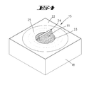
- the filter material 11 is stored in a, the Blasstutzen 10 assignable cassette 15.
- the filter material 11 is folded like an accordion and inserted into the cassette 15.
- the accordion-like folding of the filter material 11 is achieved by pleating, ie by formation of outer side and inner folds 16, 17 surrounding the inner surface of the tubular jacket, which are distributed uniformly over the length of the filter material 11 (cf. Fig. 5 ).
- the tubular filter material 11 of the illustrated first embodiment is viewed over the length provided with a constant diameter, d. H. Further, both with a constant diameter with respect to the outer folds 16 having regions as well as with a constant diameter of the inner folds 17 having regions, each with respect to the collapsed position within the cassette 15. There is such a total cylindrical, tubular filter material 11 with indicated circular cross-section, the diameter changed under unfolding to form a dust filter bag 5, beyond also with over the length of different cross-sections can be present due to the Auffaltelung.
- the cassette contour is ground plan, in particular with respect to the inner contour adapted to the outer contour of folded into a stack, folded filter material 11, so that the latter rests in the cassette 15 at least in the Faltelungsebene not displaceable.
- the cassette 15 initially has a peripheral wall 18 which is oriented transversely to the folding plane of the filter material 11. Its height is determined by the package height of the inserted, folded filter material 11 in the initial use position.
- a parallel to the Faltelungsebene the filter material 11 aligned cassette bottom 19 is centrally provided with an adapted to the outer contour of the Blasstutzens opening 20.
- this opening 20 is encompassed by a cassette sleeve 21 extending over the cassette height and running coaxially with the cassette wall 18. This ends, starting from the cassette bottom 19, in the plane of a cassette ceiling 22 running parallel to the cassette bottom 19.
- a spring element can be provided assigned to the cassette bottom 19, which loads the filter material package in the direction of the removal opening 23.
- lip-shaped circumferential seals 25 and 26 are provided.
- an outer seal 25 is assigned to the radially outer edge of the removal opening 23, this being fixed to the cassette ceiling 22.
- This outer seal 25 lies with its free, radially inner circumferential sealing surface on the facing outer surface of the protruding from the cassette 15 wall of the filter material 11 on.
- a radially inner seal 26, attached to the cassette sleeve 21 acts in the region of the removal opening 23 against the inwardly facing wall surface of the guided out of the cassette 15 filter material 11th
- the cassette 15 provided with the folded filter material 11 is arranged for fitting the vacuum cleaner 1 on the chassis ceiling 12 in such a way that the blow nozzle 10 passes through the cassette 15 in the region of the cassette sleeve 21.
- the nozzle closure flap 14 extends approximately in the plane of the cassette ceiling 22. After pivoting back the filter chamber 4 in the chamber closure position according to Fig. 2 the vacuum cleaner 1 is ready.
- the thus assembled dust filter bag 5 is blown through the blast nozzle 10 with dust and dirt-laden air, which air passes through the air-permeable Filtermaterialwandung to the outside.
- the blower unit 3 provided in the base unit 2 acts as a suction blower, which acts via a flow channel 30, which passes through the chassis ceiling 12 and communicates with the intermediate space 29 left between the filter chamber wall and the dust bag wall.
- the seals 25 and 26 provided in the region of the cassette-side removal opening 23 prevent the entry of dust and dirt particles introduced into the dust filter bag 5 via the blow nozzle 10 into the cassette 15, so that the filter material storage section inserted in the cassette 15 is not contaminated.
- prefabricated dust filter bag 5 acts in a conventional manner dirt and Staubabscheidendend.
- the dust filter bag 5 formed by the filter material 11 in the filter chamber 4 for disposal thereof is separated from the further stored in the cartridge 15 filter material 11 and the latter for training another dust filter bag 5 prepared.
- a closure of the dust filter bag 5 formed and filled in the filter chamber 4 takes place in the region opposite the bottom closure 24, ie the cassette 15.
- This bag closure is preferably triggered by the user, for example via a key command, this further, for example, after displaying a detected maximum bag level.
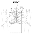
- the vacuum cleaner-side closing means 28 are moved, for example by an electric motor or alternatively manually operable lever in an operative position in which they are moved with respect to the illustrated schematic embodiment radially inward toward the enforcement section 27 of the dust filter bag 5 passing through extension of the Blasstutzenachse to a position in which the filter material wall portions of the enforcement portion 27 are superposed (see. Fig. 3 ).
- the closure means 28 initially act as a displacement means for preparing an opening closure 31 of the prefabricated dust filter bag 5.
- the closure means 28 further serve to form the opening closure 31, further also to form a bottom closure 24 of the cassette 15 ready for Nachschung filter material area and have for this purpose electrically contactable, the filter material 11 exposed metal wires 32 on.
- Each closure means 28 has two in superposition with each other spaced metal wires 32, wherein the upper metal wires 32 are used to form the opening closure 31 of the prefabricated dust filter bag 5 and the lower metal wires 32 for forming the bottom closure 24 of the downstream filter material section.
- the respective closure can be achieved by welding under pressure.
- the filter material 11 in the enforcement portion 27 wall inside, d. H. on the facing, in the closed position superimposed areas on a laminated plastic film on which superimposed film sections are welded together by the action of heat via the electrically contacted metal wires 32.
- the laminated plastic film sections are provided at regular intervals of the continuous filter material, which corresponds to distances of the length of a dust filter bag 5 to be assembled.
- the filter bag 5 is separated from the remaining section of the filter material 11 stored in the cassette 15, this continues in the area between the opening closure 31 and the bottom closure 24 In the first embodiment, this separation is shown only schematically, symbolized by a pair of scissors.
- a constructive solution provides a scissor-like arrangement of cutting blades, which are mechanically, optionally electromotively spent to sever the filter material 11 in a cutting position.
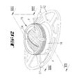
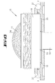
- the 6 to 20 show an exemplary constructive solution.
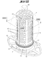
- the filter material 11 stockpiled cassette 15 is in the form of a rotationally symmetrical housing. This is provided with an external thread for screw fixing the filter chamber. 4
- cassette sleeve 21 formed in the illustrated embodiment, an axial extension of the Blasstutzens.
- the cassette sleeve 21 facing the base unit-side blowing nozzle 10 is provided with a circumferential seal 33.
- the neck closure flap 14 is arranged in the illustrated embodiment, the mouth side of the cassette shell 21, so that this contaminated by the vacuum cleaner flap 14 is replaced in the course of a cassette change with.
- leg spring 24 acts on the flap 14 in the direction of its closed position.
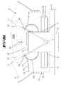
- the closure means 28 are in the second embodiment part of the interchangeable cassette 15. These are each designed as semicircular annular elements whose free ring ends are arranged on a common pivot axis y. This pivot axis y extends parallel to the cassette bottom 19, wherein further the annular portion-shaped closure means 28 in an initial position, d. H. are aligned in a non-use position in parallel alignment with the cassette bottom 19 in vertical spacing therefrom.
- The, the pivot axis y ausformenden, from the free ends of the closure means 28 radially outwardly projecting pivot pin 36 are guided by the cassette wall 18 radially outward for rotationally fixed coupling of the closure means 28 with Hassis beauen operating levers 37 in the cassette operating position.
- the operating lever 37 are accessible after operation of removing the filter chamber 4 and corresponding exposure of the filter material 11 formed from the optionally filled dust filter bag 5.
- the annular portion-shaped closure means 28 are pivoted from its ground-parallel position to move under each other of the closure means side annular surfaces.
- the latter show, as from the detailed representation in Fig. 17 to recognize, in accordance with the first embodiment, electrically contactable metal wires 32, for welding the here preferably the inside wall with a plastic film 47 laminated enforcement section 27.
- the metal wires 32 are arranged in pairs, so that in the region of each closure two mutually parallel welding zones result, which secure the closure.
- the electrical contacting of the metal wires 32 is achieved via the outwardly guided pivot pin 36, which are connected in the storage area of the chassis-side operating lever 37 with a device-side power supply, for example in the form of sliding contacts.
- the closure means 28 further have in the area between the welding zones for creating the bottom closure 24 and the opening closure 31 in opposite directions aligned cutting edges 38, the separation of the opening side sealed dust filter bag 5 from the protruding from the cassette 15, serving to form the next dust filter bag 5 filter material area.
- the cutting edges 38 of the closure means 28 are provided partially over the circumferential length of the respective closure means 28, so that only a partial penetration of the filter material 11 is made via the cutting edges 38. Accordingly, after formation of the bottom closure 24 and the opening closure 31, a perforation 39 occurs between the closure zones, along which the user can sever the filled and sealed dust filter bag 5 by tearing along the perforation line.
- Fig. 21 shows a perspective view of a filled, closed on all sides and separated dust filter bag. 5
- the filter chamber 4 illustrated with reference to the second embodiment has, opposite and in an imaginary extension to the blowing nozzle 10, a chamber outlet channel 40 which is connected in terms of air flow to the vacuum cleaner-side blower unit 3.
- the nozzle 40 is on the inside covered by a sieve-like retaining element 41st
- the filter chamber 4 is provided on the inside with a circular cylindrical supporting grid 42, for stabilizing the shape of the filter chamber 4 constructed in the dust filter bag 5.
- the dust filter bag is rail-guided positional orientation, including the dust filter bag 5, for example in the region of the outer folds 16, for example in the is provided between two spaced-apart outer folds 16 adjusting areas with radially projecting pin 43. These are arranged diametrically opposite and engage in corresponding, perpendicular to the cassette bottom 19 aligned rails 44 of the retaining element 41 (see. Fig. 23 ).
- the pins 43 are formed in a development as axial, ie transverse to the Faltelungsebene directed ribs, further in one piece and of uniform material formed from the filter material.
- Fig. 24 shows an alternative solution for closing the bottom or for closing the bag opening.
- a wrapping of the area to be closed is provided.
- the wrapping material 45 may be, for example, a yarn or a metal wire, further for example a plastic clip or the like.
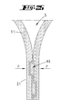
- the bottom closure 24 and / or the opening closure 31 can be produced by a pressure closure 46 (cf. Fig. 25 ).
- a pressure closure 46 (cf. Fig. 25 ).
- the facing surfaces have depressions and opposite elevations, which viewed in cross section in the manner of a dovetail connection under pressure (arrows P) are joined together.
- FIGS. 26 to 29 show two further embodiments of a magazineable, in a cassette 15 to be stocked filter material 11 for forming prefabricated dust filter bag 5 and each one of the filter material 11 by closure and separation from the filter material storage residue separated dust filter bag. 5
- FIGS. 26 and 27 show an embodiment in which by packaging a substantially circular cylindrical dust filter bag 5 can be produced.
- the vertical distances of the folds (outer folds 16 and inner folds 1) running transversely to the longitudinal extent of the dust filter bag 5 are uniform and in relation to the vertical distances of the folds in the filter material storage position according to FIG Fig. 26 significantly enlarged.
- the ratio of inner diameter to outer diameter in the storage position of the filter material 11, ie further the ratio of the diameter of inner folds 17 to outer folds 16 is chosen so large considering the centrally through the filter material supply passing through blast nozzle 10 and the permeating cassette sleeve 21 that a possible thin storage position is achieved, which is favorable to the stockpiling in the cassette 15 effects.
- the length of a filter material 11 according to Fig. 26 manufactured dust filter bag 5 individually adjustable, since not necessarily predefined closure areas must be formed in the filter material 11.
- FIGS. 28 and 29 show an embodiment in which the closing and separating regions of the filter material 11 are defined and formed at equal longitudinal intervals of the filter material 11. This is also given by the selected shape of the filter material 11 to be produced from the dust filter bag 5. This is rotationally symmetrical oval or in the form of a sphere formed with diametrically opposed bottom and opening closures 24, 31. This bag shape also requires an alternative reduction in diameter and diameter over the length of the tubular endless filter material, such that the elongated orientation of the continuous filter material a pearl chain-like structuring is recognizable, wherein the diameter-reduced sections define the closure regions.
- the numerical bandwidths given in each case also include all intermediate values, if not already indicated by way of example anyway, and in particular in 1/10 increments, restricted from the lower and / or upper limit to the respective other limit.
- "And” stands for the fact that both borders are shifted by one or more tenths to the limit, d. H. be limited.
Landscapes
- Engineering & Computer Science (AREA)
- Mechanical Engineering (AREA)
- Filters For Electric Vacuum Cleaners (AREA)
- Filtering Of Dispersed Particles In Gases (AREA)
Applications Claiming Priority (2)
| Application Number | Priority Date | Filing Date | Title |
|---|---|---|---|
| DE200810062601 DE102008062601A1 (de) | 2008-12-17 | 2008-12-17 | Verfahren zum Betreiben eines Staubsaugers sowie elektromotorisch betriebener Staubsauger und schlauchförmiger Filtermaterialvorrat |
| EP09177625.2A EP2201877B9 (fr) | 2008-12-17 | 2009-12-01 | Procédé de fonctionnement d'un aspirateur, ainsi qu'aspirateur à moteur électrique et réservoir de matériau de filtre en forme de tuyau |
Related Parent Applications (3)
| Application Number | Title | Priority Date | Filing Date |
|---|---|---|---|
| EP09177625.2 Division | 2009-12-01 | ||
| EP09177625.2A Division-Into EP2201877B9 (fr) | 2008-12-17 | 2009-12-01 | Procédé de fonctionnement d'un aspirateur, ainsi qu'aspirateur à moteur électrique et réservoir de matériau de filtre en forme de tuyau |
| EP09177625.2A Division EP2201877B9 (fr) | 2008-12-17 | 2009-12-01 | Procédé de fonctionnement d'un aspirateur, ainsi qu'aspirateur à moteur électrique et réservoir de matériau de filtre en forme de tuyau |
Publications (3)
| Publication Number | Publication Date |
|---|---|
| EP2387928A2 true EP2387928A2 (fr) | 2011-11-23 |
| EP2387928A3 EP2387928A3 (fr) | 2013-08-14 |
| EP2387928B1 EP2387928B1 (fr) | 2016-10-19 |
Family
ID=42082729
Family Applications (2)
| Application Number | Title | Priority Date | Filing Date |
|---|---|---|---|
| EP09177625.2A Not-in-force EP2201877B9 (fr) | 2008-12-17 | 2009-12-01 | Procédé de fonctionnement d'un aspirateur, ainsi qu'aspirateur à moteur électrique et réservoir de matériau de filtre en forme de tuyau |
| EP11176242.3A Not-in-force EP2387928B1 (fr) | 2008-12-17 | 2009-12-01 | Procédé de fonctionnement d'un aspirateur, ainsi qu'aspirateur à moteur électrique et réservoir de matériau de filtre en forme de tuyau |
Family Applications Before (1)
| Application Number | Title | Priority Date | Filing Date |
|---|---|---|---|
| EP09177625.2A Not-in-force EP2201877B9 (fr) | 2008-12-17 | 2009-12-01 | Procédé de fonctionnement d'un aspirateur, ainsi qu'aspirateur à moteur électrique et réservoir de matériau de filtre en forme de tuyau |
Country Status (4)
| Country | Link |
|---|---|
| EP (2) | EP2201877B9 (fr) |
| CN (2) | CN101797136A (fr) |
| DE (1) | DE102008062601A1 (fr) |
| ES (2) | ES2608702T3 (fr) |
Families Citing this family (5)
| Publication number | Priority date | Publication date | Assignee | Title |
|---|---|---|---|---|
| CN103082953A (zh) * | 2011-10-31 | 2013-05-08 | 梁运跃 | 一种拖地清洁装置 |
| DE102016104787A1 (de) * | 2016-03-15 | 2017-09-21 | Alfred Kärcher Gmbh & Co. Kg | Saugvorrichtung, Saugbeutel-Haltevorrichtung und Verfahren zum Betreiben einer Saugvorrichtung |
| KR102431691B1 (ko) * | 2018-01-29 | 2022-08-11 | 엘지전자 주식회사 | 청소기 |
| DK3821776T3 (da) * | 2019-11-12 | 2025-02-03 | Eurofilters Holding Nv | Støvsugerfilterpose til håndstøvsuger |
| DE102019217867A1 (de) * | 2019-11-20 | 2021-05-20 | Robert Bosch Gmbh | Akkusaugervorrichtung, Akkusauger und Saugersystem |
Family Cites Families (9)
| Publication number | Priority date | Publication date | Assignee | Title |
|---|---|---|---|---|
| NL89029C (fr) * | 1951-09-01 | |||
| DE2139671A1 (de) * | 1971-08-07 | 1973-02-15 | Siemens Elektrogeraete Gmbh | Elektrischer staubsauger |
| SE379147B (fr) * | 1973-11-28 | 1975-09-29 | Electrolux Ab | |
| GB2140288B (en) * | 1981-05-07 | 1985-06-26 | Hoover Plc | Suction cleaners |
| SE461068B (sv) * | 1987-12-21 | 1990-01-08 | Electrolux Ab | Dammsugare |
| JPH0315426A (ja) * | 1989-10-28 | 1991-01-23 | Hitachi Ltd | 電気掃除機 |
| SE521474C2 (sv) * | 2002-03-08 | 2003-11-04 | Electrolux Ab | Anordning vid en dammsugare samt kassett för användning vid anordningen |
| US7332005B2 (en) * | 2003-02-28 | 2008-02-19 | The Hoover Company | Filtration bag replacement system for a floor care appliance |
| TWI395567B (zh) * | 2005-02-28 | 2013-05-11 | 松下電器產業股份有限公司 | Vacuum cleaners for electric vacuum cleaners and electric vacuum cleaners |
-
2008
- 2008-12-17 DE DE200810062601 patent/DE102008062601A1/de not_active Ceased
-
2009
- 2009-12-01 ES ES11176242.3T patent/ES2608702T3/es active Active
- 2009-12-01 EP EP09177625.2A patent/EP2201877B9/fr not_active Not-in-force
- 2009-12-01 ES ES09177625.2T patent/ES2658098T3/es active Active
- 2009-12-01 EP EP11176242.3A patent/EP2387928B1/fr not_active Not-in-force
- 2009-12-17 CN CN200911000287A patent/CN101797136A/zh active Pending
- 2009-12-17 CN CN201210067264.XA patent/CN102578969B/zh not_active Expired - Fee Related
Non-Patent Citations (1)
| Title |
|---|
| None |
Also Published As
| Publication number | Publication date |
|---|---|
| CN102578969B (zh) | 2015-09-30 |
| CN101797136A (zh) | 2010-08-11 |
| EP2201877B9 (fr) | 2018-03-21 |
| EP2387928B1 (fr) | 2016-10-19 |
| ES2608702T3 (es) | 2017-04-12 |
| EP2201877B1 (fr) | 2017-11-01 |
| EP2201877A3 (fr) | 2011-02-16 |
| ES2658098T9 (es) | 2018-05-07 |
| ES2658098T3 (es) | 2018-03-08 |
| EP2387928A3 (fr) | 2013-08-14 |
| EP2201877A2 (fr) | 2010-06-30 |
| DE102008062601A1 (de) | 2010-06-24 |
| CN102578969A (zh) | 2012-07-18 |
Similar Documents
| Publication | Publication Date | Title |
|---|---|---|
| EP2387928B1 (fr) | Procédé de fonctionnement d'un aspirateur, ainsi qu'aspirateur à moteur électrique et réservoir de matériau de filtre en forme de tuyau | |
| DE102010038095B4 (de) | Entleerungsstation für einen akkumulatorbetriebenen Elektrostaubsauger | |
| EP2866631B1 (fr) | Combinaison d'un mini-aspirateur et d'un boîtier d'aspirateur ainsi que mini-aspirateur et boîtier d'aspirateur | |
| DE202004021292U1 (de) | Handstaubsauger | |
| DE3241991A1 (de) | Staubsauger | |
| EP0289709B1 (fr) | Aspirateur électrique | |
| DE102015105059B4 (de) | Filteranordnung, Haushaltsgerät mit einer Filteranordnung und Verfahren zum Wechseln eines Filters | |
| EP2923624A2 (fr) | Sac de filtre à poussière pour un aspirateur et système d'un sac de filtre à poussière dans un aspirateur | |
| DE112009002152T5 (de) | Beutelankoppelanordnung für einen Staubsauger | |
| DE102008011723A1 (de) | Staubsauger, insbesondere Haushalts-Staubsauger, sowie Verfahren zum Betreiben eines Staubsaugers | |
| DE102010016256A1 (de) | Verfahren zum Betreiben eines Staubsaugers, insbesondere eines selbsttätig verfahrbaren Saug- und/oder Kehrgeräts sowie ein derartiges Gerät und lagenförmiger Filtermaterialvorrat | |
| EP0289710A1 (fr) | Disposition de sacs filtrants dans des aspirateurs électriques | |
| DE102009034955B4 (de) | Selbsttätig verfahrbares Bodenstaub-Aufsammelgerät | |
| DE3743083C2 (de) | Handstaubsauger | |
| DE102019115190A1 (de) | Entsorgungsstation | |
| EP2380477B1 (fr) | Aspirateur électrique avec tubulure pour coopérer avec un sac à poussière | |
| DE102013108905A1 (de) | Zur Feuchtreinigung ausgebildetes Reinigungsgerät | |
| DE927893C (de) | Staubsauger | |
| DE202007000103U1 (de) | Staubbehälter, insbesondere für Staubsauger | |
| DE4341248A1 (de) | Staubfilterbeutel für einen Staubsauger | |
| EP4061192B1 (fr) | Dispositif sous vide à batterie, collecteur sous vide à batterie et système de collecteur sous vide | |
| DE102010041832B4 (de) | Staubsauger und Verfahren zum Entleeren eines Staubsammelbehälters aus einem Staubsauger | |
| DE102009053697A1 (de) | Handstaubsauger mit einer Motor-Gebläse-Einheit sowie Filterbeutel | |
| DE947513C (de) | Einrichtung zum Abscheiden von Staub, Schmutz oder aehnlichen Fremdkoerpern aus Luft | |
| DE202005002811U1 (de) | Klemme zur Fixierung eines Elements aus flexiblem Material, bevorzugt für einen Einlagebeutel im Aufnahmetopf einer Luftansaugvorrichtung |
Legal Events
| Date | Code | Title | Description |
|---|---|---|---|
| AC | Divisional application: reference to earlier application |
Ref document number: 2201877 Country of ref document: EP Kind code of ref document: P |
|
| AK | Designated contracting states |
Kind code of ref document: A2 Designated state(s): AT BE BG CH CY CZ DE DK EE ES FI FR GB GR HR HU IE IS IT LI LT LU LV MC MK MT NL NO PL PT RO SE SI SK SM TR |
|
| AX | Request for extension of the european patent |
Extension state: AL BA RS |
|
| PUAI | Public reference made under article 153(3) epc to a published international application that has entered the european phase |
Free format text: ORIGINAL CODE: 0009012 |
|
| PUAL | Search report despatched |
Free format text: ORIGINAL CODE: 0009013 |
|
| AK | Designated contracting states |
Kind code of ref document: A3 Designated state(s): AT BE BG CH CY CZ DE DK EE ES FI FR GB GR HR HU IE IS IT LI LT LU LV MC MK MT NL NO PL PT RO SE SI SK SM TR |
|
| AX | Request for extension of the european patent |
Extension state: AL BA RS |
|
| RIC1 | Information provided on ipc code assigned before grant |
Ipc: A47L 9/14 20060101AFI20130711BHEP |
|
| 17P | Request for examination filed |
Effective date: 20131014 |
|
| RBV | Designated contracting states (corrected) |
Designated state(s): AT BE BG CH CY CZ DE DK EE ES FI FR GB GR HR HU IE IS IT LI LT LU LV MC MK MT NL NO PL PT RO SE SI SK SM TR |
|
| GRAP | Despatch of communication of intention to grant a patent |
Free format text: ORIGINAL CODE: EPIDOSNIGR1 |
|
| INTG | Intention to grant announced |
Effective date: 20160513 |
|
| GRAS | Grant fee paid |
Free format text: ORIGINAL CODE: EPIDOSNIGR3 |
|
| GRAA | (expected) grant |
Free format text: ORIGINAL CODE: 0009210 |
|
| AC | Divisional application: reference to earlier application |
Ref document number: 2201877 Country of ref document: EP Kind code of ref document: P |
|
| AK | Designated contracting states |
Kind code of ref document: B1 Designated state(s): AT BE BG CH CY CZ DE DK EE ES FI FR GB GR HR HU IE IS IT LI LT LU LV MC MK MT NL NO PL PT RO SE SI SK SM TR |
|
| REG | Reference to a national code |
Ref country code: GB Ref legal event code: FG4D Free format text: NOT ENGLISH |
|
| REG | Reference to a national code |
Ref country code: CH Ref legal event code: EP |
|
| REG | Reference to a national code |
Ref country code: AT Ref legal event code: REF Ref document number: 837595 Country of ref document: AT Kind code of ref document: T Effective date: 20161115 |
|
| REG | Reference to a national code |
Ref country code: IE Ref legal event code: FG4D Free format text: LANGUAGE OF EP DOCUMENT: GERMAN |
|
| REG | Reference to a national code |
Ref country code: DE Ref legal event code: R096 Ref document number: 502009013267 Country of ref document: DE |
|
| REG | Reference to a national code |
Ref country code: FR Ref legal event code: PLFP Year of fee payment: 8 |
|
| REG | Reference to a national code |
Ref country code: NL Ref legal event code: MP Effective date: 20161019 |
|
| REG | Reference to a national code |
Ref country code: LT Ref legal event code: MG4D |
|
| PG25 | Lapsed in a contracting state [announced via postgrant information from national office to epo] |
Ref country code: LV Free format text: LAPSE BECAUSE OF FAILURE TO SUBMIT A TRANSLATION OF THE DESCRIPTION OR TO PAY THE FEE WITHIN THE PRESCRIBED TIME-LIMIT Effective date: 20161019 |
|
| REG | Reference to a national code |
Ref country code: ES Ref legal event code: FG2A Ref document number: 2608702 Country of ref document: ES Kind code of ref document: T3 Effective date: 20170412 |
|
| PG25 | Lapsed in a contracting state [announced via postgrant information from national office to epo] |
Ref country code: SE Free format text: LAPSE BECAUSE OF FAILURE TO SUBMIT A TRANSLATION OF THE DESCRIPTION OR TO PAY THE FEE WITHIN THE PRESCRIBED TIME-LIMIT Effective date: 20161019 Ref country code: NO Free format text: LAPSE BECAUSE OF FAILURE TO SUBMIT A TRANSLATION OF THE DESCRIPTION OR TO PAY THE FEE WITHIN THE PRESCRIBED TIME-LIMIT Effective date: 20170119 Ref country code: LT Free format text: LAPSE BECAUSE OF FAILURE TO SUBMIT A TRANSLATION OF THE DESCRIPTION OR TO PAY THE FEE WITHIN THE PRESCRIBED TIME-LIMIT Effective date: 20161019 Ref country code: GR Free format text: LAPSE BECAUSE OF FAILURE TO SUBMIT A TRANSLATION OF THE DESCRIPTION OR TO PAY THE FEE WITHIN THE PRESCRIBED TIME-LIMIT Effective date: 20170120 |
|
| PG25 | Lapsed in a contracting state [announced via postgrant information from national office to epo] |
Ref country code: IS Free format text: LAPSE BECAUSE OF FAILURE TO SUBMIT A TRANSLATION OF THE DESCRIPTION OR TO PAY THE FEE WITHIN THE PRESCRIBED TIME-LIMIT Effective date: 20170219 Ref country code: PT Free format text: LAPSE BECAUSE OF FAILURE TO SUBMIT A TRANSLATION OF THE DESCRIPTION OR TO PAY THE FEE WITHIN THE PRESCRIBED TIME-LIMIT Effective date: 20170220 Ref country code: HR Free format text: LAPSE BECAUSE OF FAILURE TO SUBMIT A TRANSLATION OF THE DESCRIPTION OR TO PAY THE FEE WITHIN THE PRESCRIBED TIME-LIMIT Effective date: 20161019 Ref country code: NL Free format text: LAPSE BECAUSE OF FAILURE TO SUBMIT A TRANSLATION OF THE DESCRIPTION OR TO PAY THE FEE WITHIN THE PRESCRIBED TIME-LIMIT Effective date: 20161019 Ref country code: PL Free format text: LAPSE BECAUSE OF FAILURE TO SUBMIT A TRANSLATION OF THE DESCRIPTION OR TO PAY THE FEE WITHIN THE PRESCRIBED TIME-LIMIT Effective date: 20161019 Ref country code: FI Free format text: LAPSE BECAUSE OF FAILURE TO SUBMIT A TRANSLATION OF THE DESCRIPTION OR TO PAY THE FEE WITHIN THE PRESCRIBED TIME-LIMIT Effective date: 20161019 |
|
| REG | Reference to a national code |
Ref country code: DE Ref legal event code: R097 Ref document number: 502009013267 Country of ref document: DE |
|
| PG25 | Lapsed in a contracting state [announced via postgrant information from national office to epo] |
Ref country code: SK Free format text: LAPSE BECAUSE OF FAILURE TO SUBMIT A TRANSLATION OF THE DESCRIPTION OR TO PAY THE FEE WITHIN THE PRESCRIBED TIME-LIMIT Effective date: 20161019 Ref country code: RO Free format text: LAPSE BECAUSE OF FAILURE TO SUBMIT A TRANSLATION OF THE DESCRIPTION OR TO PAY THE FEE WITHIN THE PRESCRIBED TIME-LIMIT Effective date: 20161019 Ref country code: DK Free format text: LAPSE BECAUSE OF FAILURE TO SUBMIT A TRANSLATION OF THE DESCRIPTION OR TO PAY THE FEE WITHIN THE PRESCRIBED TIME-LIMIT Effective date: 20161019 Ref country code: EE Free format text: LAPSE BECAUSE OF FAILURE TO SUBMIT A TRANSLATION OF THE DESCRIPTION OR TO PAY THE FEE WITHIN THE PRESCRIBED TIME-LIMIT Effective date: 20161019 |
|
| REG | Reference to a national code |
Ref country code: CH Ref legal event code: PL |
|
| PLBE | No opposition filed within time limit |
Free format text: ORIGINAL CODE: 0009261 |
|
| STAA | Information on the status of an ep patent application or granted ep patent |
Free format text: STATUS: NO OPPOSITION FILED WITHIN TIME LIMIT |
|
| PG25 | Lapsed in a contracting state [announced via postgrant information from national office to epo] |
Ref country code: BG Free format text: LAPSE BECAUSE OF FAILURE TO SUBMIT A TRANSLATION OF THE DESCRIPTION OR TO PAY THE FEE WITHIN THE PRESCRIBED TIME-LIMIT Effective date: 20170119 Ref country code: SM Free format text: LAPSE BECAUSE OF FAILURE TO SUBMIT A TRANSLATION OF THE DESCRIPTION OR TO PAY THE FEE WITHIN THE PRESCRIBED TIME-LIMIT Effective date: 20161019 |
|
| 26N | No opposition filed |
Effective date: 20170720 |
|
| GBPC | Gb: european patent ceased through non-payment of renewal fee |
Effective date: 20170119 |
|
| PG25 | Lapsed in a contracting state [announced via postgrant information from national office to epo] |
Ref country code: MC Free format text: LAPSE BECAUSE OF FAILURE TO SUBMIT A TRANSLATION OF THE DESCRIPTION OR TO PAY THE FEE WITHIN THE PRESCRIBED TIME-LIMIT Effective date: 20161019 |
|
| REG | Reference to a national code |
Ref country code: IE Ref legal event code: MM4A |
|
| PG25 | Lapsed in a contracting state [announced via postgrant information from national office to epo] |
Ref country code: LI Free format text: LAPSE BECAUSE OF NON-PAYMENT OF DUE FEES Effective date: 20161231 Ref country code: LU Free format text: LAPSE BECAUSE OF NON-PAYMENT OF DUE FEES Effective date: 20161201 Ref country code: CH Free format text: LAPSE BECAUSE OF NON-PAYMENT OF DUE FEES Effective date: 20161231 |
|
| PG25 | Lapsed in a contracting state [announced via postgrant information from national office to epo] |
Ref country code: SI Free format text: LAPSE BECAUSE OF FAILURE TO SUBMIT A TRANSLATION OF THE DESCRIPTION OR TO PAY THE FEE WITHIN THE PRESCRIBED TIME-LIMIT Effective date: 20161019 Ref country code: GB Free format text: LAPSE BECAUSE OF NON-PAYMENT OF DUE FEES Effective date: 20170119 Ref country code: IE Free format text: LAPSE BECAUSE OF NON-PAYMENT OF DUE FEES Effective date: 20161201 |
|
| REG | Reference to a national code |
Ref country code: FR Ref legal event code: PLFP Year of fee payment: 9 |
|
| PG25 | Lapsed in a contracting state [announced via postgrant information from national office to epo] |
Ref country code: HU Free format text: LAPSE BECAUSE OF FAILURE TO SUBMIT A TRANSLATION OF THE DESCRIPTION OR TO PAY THE FEE WITHIN THE PRESCRIBED TIME-LIMIT; INVALID AB INITIO Effective date: 20091201 Ref country code: CY Free format text: LAPSE BECAUSE OF FAILURE TO SUBMIT A TRANSLATION OF THE DESCRIPTION OR TO PAY THE FEE WITHIN THE PRESCRIBED TIME-LIMIT Effective date: 20161019 |
|
| PG25 | Lapsed in a contracting state [announced via postgrant information from national office to epo] |
Ref country code: MK Free format text: LAPSE BECAUSE OF FAILURE TO SUBMIT A TRANSLATION OF THE DESCRIPTION OR TO PAY THE FEE WITHIN THE PRESCRIBED TIME-LIMIT Effective date: 20161019 Ref country code: TR Free format text: LAPSE BECAUSE OF FAILURE TO SUBMIT A TRANSLATION OF THE DESCRIPTION OR TO PAY THE FEE WITHIN THE PRESCRIBED TIME-LIMIT Effective date: 20161019 |
|
| PG25 | Lapsed in a contracting state [announced via postgrant information from national office to epo] |
Ref country code: MT Free format text: LAPSE BECAUSE OF FAILURE TO SUBMIT A TRANSLATION OF THE DESCRIPTION OR TO PAY THE FEE WITHIN THE PRESCRIBED TIME-LIMIT Effective date: 20161019 |
|
| PGFP | Annual fee paid to national office [announced via postgrant information from national office to epo] |
Ref country code: CZ Payment date: 20191120 Year of fee payment: 11 |
|
| PGFP | Annual fee paid to national office [announced via postgrant information from national office to epo] |
Ref country code: AT Payment date: 20191213 Year of fee payment: 11 |
|
| PG25 | Lapsed in a contracting state [announced via postgrant information from national office to epo] |
Ref country code: CZ Free format text: LAPSE BECAUSE OF NON-PAYMENT OF DUE FEES Effective date: 20201201 |
|
| REG | Reference to a national code |
Ref country code: AT Ref legal event code: MM01 Ref document number: 837595 Country of ref document: AT Kind code of ref document: T Effective date: 20201201 |
|
| PG25 | Lapsed in a contracting state [announced via postgrant information from national office to epo] |
Ref country code: AT Free format text: LAPSE BECAUSE OF NON-PAYMENT OF DUE FEES Effective date: 20201201 |
|
| PGFP | Annual fee paid to national office [announced via postgrant information from national office to epo] |
Ref country code: FR Payment date: 20221219 Year of fee payment: 14 |
|
| PGFP | Annual fee paid to national office [announced via postgrant information from national office to epo] |
Ref country code: BE Payment date: 20221220 Year of fee payment: 14 |
|
| PGFP | Annual fee paid to national office [announced via postgrant information from national office to epo] |
Ref country code: ES Payment date: 20230119 Year of fee payment: 14 |
|
| PGFP | Annual fee paid to national office [announced via postgrant information from national office to epo] |
Ref country code: IT Payment date: 20221230 Year of fee payment: 14 Ref country code: DE Payment date: 20221221 Year of fee payment: 14 |
|
| P01 | Opt-out of the competence of the unified patent court (upc) registered |
Effective date: 20230517 |
|
| REG | Reference to a national code |
Ref country code: DE Ref legal event code: R119 Ref document number: 502009013267 Country of ref document: DE |
|
| REG | Reference to a national code |
Ref country code: BE Ref legal event code: MM Effective date: 20231231 |
|
| PG25 | Lapsed in a contracting state [announced via postgrant information from national office to epo] |
Ref country code: DE Free format text: LAPSE BECAUSE OF NON-PAYMENT OF DUE FEES Effective date: 20240702 |
|
| PG25 | Lapsed in a contracting state [announced via postgrant information from national office to epo] |
Ref country code: BE Free format text: LAPSE BECAUSE OF NON-PAYMENT OF DUE FEES Effective date: 20231231 |
|
| PG25 | Lapsed in a contracting state [announced via postgrant information from national office to epo] |
Ref country code: FR Free format text: LAPSE BECAUSE OF NON-PAYMENT OF DUE FEES Effective date: 20231231 |
|
| PG25 | Lapsed in a contracting state [announced via postgrant information from national office to epo] |
Ref country code: FR Free format text: LAPSE BECAUSE OF NON-PAYMENT OF DUE FEES Effective date: 20231231 Ref country code: DE Free format text: LAPSE BECAUSE OF NON-PAYMENT OF DUE FEES Effective date: 20240702 Ref country code: BE Free format text: LAPSE BECAUSE OF NON-PAYMENT OF DUE FEES Effective date: 20231231 |
|
| REG | Reference to a national code |
Ref country code: ES Ref legal event code: FD2A Effective date: 20250124 |
|
| PG25 | Lapsed in a contracting state [announced via postgrant information from national office to epo] |
Ref country code: ES Free format text: LAPSE BECAUSE OF NON-PAYMENT OF DUE FEES Effective date: 20231202 |
|
| PG25 | Lapsed in a contracting state [announced via postgrant information from national office to epo] |
Ref country code: IT Free format text: LAPSE BECAUSE OF NON-PAYMENT OF DUE FEES Effective date: 20231201 |