EP2388191A2 - Rotor ouvert contra-rotatif (CROR) - Google Patents
Rotor ouvert contra-rotatif (CROR) Download PDFInfo
- Publication number
- EP2388191A2 EP2388191A2 EP11166634A EP11166634A EP2388191A2 EP 2388191 A2 EP2388191 A2 EP 2388191A2 EP 11166634 A EP11166634 A EP 11166634A EP 11166634 A EP11166634 A EP 11166634A EP 2388191 A2 EP2388191 A2 EP 2388191A2
- Authority
- EP
- European Patent Office
- Prior art keywords
- rotor
- commanded
- beta1
- blade angle
- cror
- Prior art date
- Legal status (The legal status is an assumption and is not a legal conclusion. Google has not performed a legal analysis and makes no representation as to the accuracy of the status listed.)
- Granted
Links
Images


Classifications
-
- B—PERFORMING OPERATIONS; TRANSPORTING
- B64—AIRCRAFT; AVIATION; COSMONAUTICS
- B64C—AEROPLANES; HELICOPTERS
- B64C11/00—Propellers, e.g. of ducted type; Features common to propellers and rotors for rotorcraft
- B64C11/30—Blade pitch-changing mechanisms
- B64C11/306—Blade pitch-changing mechanisms specially adapted for contrarotating propellers
-
- B—PERFORMING OPERATIONS; TRANSPORTING
- B64—AIRCRAFT; AVIATION; COSMONAUTICS
- B64D—EQUIPMENT FOR FITTING IN OR TO AIRCRAFT; FLIGHT SUITS; PARACHUTES; ARRANGEMENT OR MOUNTING OF POWER PLANTS OR PROPULSION TRANSMISSIONS IN AIRCRAFT
- B64D27/00—Arrangement or mounting of power plants in aircraft; Aircraft characterised by the type or position of power plants
- B64D2027/005—Aircraft with an unducted turbofan comprising contra-rotating rotors, e.g. contra-rotating open rotors [CROR]
-
- Y—GENERAL TAGGING OF NEW TECHNOLOGICAL DEVELOPMENTS; GENERAL TAGGING OF CROSS-SECTIONAL TECHNOLOGIES SPANNING OVER SEVERAL SECTIONS OF THE IPC; TECHNICAL SUBJECTS COVERED BY FORMER USPC CROSS-REFERENCE ART COLLECTIONS [XRACs] AND DIGESTS
- Y02—TECHNOLOGIES OR APPLICATIONS FOR MITIGATION OR ADAPTATION AGAINST CLIMATE CHANGE
- Y02T—CLIMATE CHANGE MITIGATION TECHNOLOGIES RELATED TO TRANSPORTATION
- Y02T50/00—Aeronautics or air transport
- Y02T50/60—Efficient propulsion technologies, e.g. for aircraft
Definitions
- the present disclosure relates to gas turbine engines, and more particularly to Beta operation of a Counter-Rotating Open-Rotor (CROR).
- CROR Counter-Rotating Open-Rotor
- a Counter-Rotating Open-Rotor includes a gas turbine engine with counter-rotating un-ducted rotors outside a nacelle structure.
- Propfans are also known as ultra-high bypass (UHB) engines and, most recently, open rotor jet engines.
- UHB ultra-high bypass
- the design is intended to offer the speed and performance of a turbofan, with the fuel economy of a turboprop.
- CRORs may have particular challenges in terms of aerodynamics, aeroacoustics and structural dynamics as the forward and aft rotors are outside the nacelle structure and are positioned relatively close together which may result in rotor/rotor interactions.
- a method of controlling a Counter-Rotating Open-Rotor (CROR) includes mechanically linking a pitch change system of a first rotor with a pitch change system of a second rotor and commanding a Blade Angle (Beta1 commanded) of the first rotor such that a Blade Angle (Beta2 Actual) of the second rotor is a function of the commanded Blade Angle (Beta1 commanded) to provide a linear relationship between an actual Blade angle (Beta1 Actual) and Beta1 commanded of the first rotor and a non-linear relationship between Beta2 Actual and Beta1 commanded.
- a method of controlling a Counter-Rotating Open-Rotor includes entering Beta Control and commanding a Blade Angle (Beta1 commanded) of the first rotor such that a Blade Angle (Beta2 Actual) of the second rotor is a function of the commanded Blade Angle (Beta1 commanded).
- a Counter-Rotating Open-Rotor includes a second pitch change system to change a pitch of a second rotor, the second pitch change system mechanically linked to a first pitch change system of a first rotor.
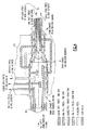
- FIG. 1 schematically illustrates a Counter-Rotating Open-Rotor (CROR) 20.
- the CROR 20 generally includes a gas turbine engine 22 with counter-rotating un-ducted rotors 24, 26 outside of a nacelle structure 28 on a central longitudinal engine axis A.
- the CROR 20 may be configured as a tractor (rotors ahead of the engine in a pulling configuration), or as a pusher (shown). Although depicted as a particular architecture in the disclosed non-limiting embodiment, it should be understood that the concepts described herein are applicable to other architectures.
- the gas turbine engine 22 generally incorporates a compressor section 30, a combustor section 32 and a turbine section 34 with a power turbine 36.
- the power turbine 36 provides a speed and torque output to drive a gear system 38 which drives the counter-rotating un-ducted rotors 24, 26.
- the sections are defined along the central longitudinal engine axis A and the gear system 38 may be located axially between the counter-rotating un-ducted rotors 24, 26.
- the gear system 38 in the disclosed non-limiting embodiment is a planetary, differential gearbox which generally includes a sun gear 40 driven by the power turbine 36, a multiple of planet gears 42, a planet carrier 44, and a ring gear 46 which rotate relative to a fixed structure 48.
- the forward rotor 24 rotates with the planet carrier 44 and the aft rotor 26 counter rotates with the ring gear 46.
- the counter-rotating un-ducted rotors 24, 26 each includes a multiple of propeller blades 24B, 26B (one shown) which are connected with the respective planet carrier 44 and ring gear 46 through a pitch change system 50, 52.
- the pitch change systems 50, 52 include an axially movable forward pitch change actuator 54 and axially movable aft pitch change actuator 56 to pitch the rotor blades 24B, 26B about a respective rotor blade axis B1, B2 to achieve the desired propeller mode such as Feather, Forward Speed Governing, CP (coefficient of power) Bucket "keep out zone", and Reverse ( Figure 3 ).
- the pitch change systems 50, 52 may include linear hydraulic actuation systems with metered pressures that may be ducted to an oil transfer tube 60 which contains at least four separate hydraulic passages ( Figure 4 ).
- Oil supplied through the oil transfer tube 60 to the pitch change actuators 54, 56 may flow through a four-land transfer bearing 62 located at the aft end of the oil transfer tube 60.
- the transfer bearing 62 provides the hydraulic connection between the stationary and rotating hardware.
- Two pressures (coarse and fine pitch - forward rotor) from the oil transfer tube 60 are provided to the forward pitch change actuator 54, while the other two pressures (coarse and fine pitch - aft rotor) are provided to the aft pitch change actuator 56 through an aft transfer bearing 64.
- Each of the pitch change actuators 54, 56 includes a dual-acting piston with differential areas sized in accordance with pitch change actuator structural and performance requirements.
- Each pitch change actuator 54, 56 includes a pitch change yoke 54Y, 56Y which transmits the linear force output of the pitch change actuator 54, 56 to a trunnion 24T, 26T at the base of each rotor blade 24B, 26B.
- a rotor control module 58 provides metering and control of oil supplied to the pitch change system 50, 52 to change the pitch of the rotors 24, 26 of the CROR 20.
- Figure 3 is a block diagram representation of functions that may be enacted in either dedicated hardware circuitry or programmed software routines capable of execution in a microprocessor based electronic control environment such as rotor control module 58.
- the rotor control module 58 uses two primary propeller control modes for a constant speed propeller system: Fixed Speed Control and Beta Control. In flight at high power, the CROR 20 is in fixed speed control mode which, in technical parlance, operates as an isochronous governor.
- the rotors 24, 26 are essentially the governor for the gas turbine engine power turbine 36. So the rotor control module 58 sets a fixed speed requirement and then adjusts rotor blade angle to absorb whatever power the gas turbine engine 22 outputs that the rotor blade speed will remain fixed. Although, there may be additional selectable rotor speeds for particular flight conditions, once that speed is selected, power change is accomplished through pitch change of the rotor blades rather than speed change to assure rotor blade frequencies are maintained in predesigned regions and optimal performance is available.
- the CP bucket "keep out zone" is the region where the rotors 24, 26 cannot be effectively controlled through a change in rotor blade pitch. For example, if a rotor blade pitch lower than the low pitch stop is commanded in flight, the forward airspeed of the aircraft may windmill the rotor which increases power to the system such that the rotor may overspeed.
- the low pitch stop is the lowest blade pitch angle in the fixed speed control mode below which the rotor speed can not be effectively controlled.
- the low pitch stop must be transited through to enter reverse pitch.
- the rotor control module 58 switches to the Beta Control mode where rotor blade pitch is directly commanded rather than speed. Beta Control mode is typically used after aircraft touch down and when the power is relatively low such as ground idle, ground operations, or reverse operations.
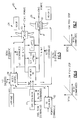
- FIG. 5 one non-limiting embodiment of a control system 80 with inputs and outputs to control the counter-rotating un-ducted rotors 24, 26 of the CROR 20.
- Mechanical connections are depicted as the heavy lines from the gas turbine engine 22 to the gear system 38 then split to the counter-rotating un-ducted rotors 24, 26.
- the heavy black line function boxes between the mechanical paths represent the mathematical relationships due to the mechanical systems.
- the rotor control module 58 communicates with the pitch change system 50, 52 and an engine control module 82 such as a Full Authority Digital Electronic Control (FADEC) that communicates with the gas turbine engine 22.
- the control modules 58, 82 execute algorithms that are disclosed in terms of functional blocks and it should be understood by those skilled in the art with the benefit of this disclosure that these functions may be enacted in either dedicated hardware circuitry or programmed software routines capable of execution in microprocessor based electronics control module embodiments of various configurations.
- Npt is the speed of the power turbine 36 and T is the torque of the power turbine 36 which is essentially the power output into the gear system 38.
- Output from the gear system 38 is two paths because the planetary differential gearbox provides the two counter-rotating outputs for the counter-rotating un-ducted rotors 24, 26.
- rotor speed is measured and is desired to be held constant.
- the rotor control module 58 may increase or decrease blade angle to absorb more or less power as provided by the gas turbine engine to maintain constant rotor speed.
- the increase or decrease signal is noted as BetaDOT for "rate of change of Beta.”
- BetaDOT rate of change of Beta
- aft rotor 26 Due to the proximity of the forward rotor 24 to the stationary structure of the gas turbine engine 22, conventional technology may be used to provide speed (Nr1) and Beta feedback to the rotor control module 58.
- the aft rotor 26 is relatively remote from the stationary structure of the gas turbine engine 22 and signals from the aft rotor 26 must pass through at least two rotating interfaces as well as the gear system 38.
- a Blade Angle feedback signal (Beta1 Feedback) and a commanded rate of change of the blade angle signal (Beta1 DOT commanded) communicate with the forward rotor 24.
- a Blade Angle feedback signal (Beta2 Feedback) and a commanded rate of change of the blade angle signal (Beta2DOT commanded) communicate with the aft rotor 26.
- commanding a rate such as changing a rotor blade angle at 3 degrees per second in the positive direction, is a rate command and is usually given a DOT for the first derivative - so BetaDOT would be rate of change of Beta.
- Rotor blade angle actual and rotor speed Nr1 may be measured directly through, for example, dual magnetic sensors attached to stationary structure adjacent to the forward rotor 24 for communication to the rotor control module 58.
- the rotational speed of the aft rotor 26 is calculated (Nr2 derived) from the mathematical functions above as follows-It is common and necessary for manufactures of gas turbine engines to measure the speed of the power turbine 36 to provide back-up protection against accidental overspeeding and to provide underspeed governing during Beta Mode operation of the rotor system.
- This signal is normally provided to the engine control 82 for that function and therefore is available to the rotor control 58.
- Beta1, Beta1DOT, Beta2, Beta2DOT, and the rotational speed of the aft rotor 26 (Nr2) speed governing is readily achieved to control blade angle and prevent the engine 22 from over speeding and maintain power within the desired limits throughout various regimes. But this requires the Beta2 and Beta2DOT signals be communicated through a multiple of rotational interfaces between the aft rotor 26 and the rotor control module 58 which may be somewhat complicated.
- the aft rotor 26 is fully usable for ground and reverse operation under Beta Control in the same manner of the forward rotor 24 ( Figures 6 and 7 ). That is, a linear relationship is provided between Beta1 Actual and Beta1 Commanded as well as between Beta2 Actual and Beta2 Commanded. This linear relationship permits a commanded negative pitch or a commanded positive pitch and the rotors 24, 26 will go to that commanded pitch. There are thus no Beta restrictions on ground operation or reverse operation.
- a feedback assembly 90 is connected to the aft pitch change actuator 56.
- the feedback assembly 90 generally includes a feedback shaft 92, a LVDT 94, a sliding joint 96 and bearings 98A, 98B.
- the feedback shaft 92 is held rotationally stationary upon bearings 98A, 98B to provide a rotationally stationary path from the aft pitch change actuator 56 to the LVDT 94.
- Bearings 98A permits rotation between the feedback shaft 92 and the forward rotor 24 while bearing 98B permits rotation between the feedback shaft 92 and the aft rotor 26.
- the feedback assembly 90 directly monitors axial position of the aft pitch change actuator 56. Such feedback may be required only below Flight Idle.
- the feedback shaft 92 includes an axial stop 92S such that the feedback shaft 92 is axially restrained above Flight Idle. Further axial movement of the aft pitch change actuator 56 above flight idle is absorbed by the sliding joint 96 such as a spring which compresses above flight idle to minimize the stroke applied to the LVDT 94.
- the stroke limitation increases the fidelity of measurement required of the LVDT 94. It should be understood that various other measurement systems may alternatively or additionally be provided.
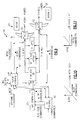
- FIG. 9 another non-limiting embodiment of a control system 100 with inputs and outputs to control the counter-rotating un-ducted rotors 24, 26 of the CROR 20.
- the rotational speed of the aft rotor 26 is calculated (Nr2 derived) from the mathematical functions as discussed above and the Beta2 feedback signal is eliminated.
- Beta Control operations such as reversing, and other such ground operations are performed by the forward rotor 24 alone as the aft rotor 26 is held fixed at the low pitch stop whenever the forward rotor 24 is commanded to a lower pitch than the low pitch stop.
- the aft rotor 26 is on the low pitch stop and the forward rotor 24 will alone move into the low blade angles and into reverse. In this configuration, the aft rotor 26 is not used for ground and reverse operation under Beta Control as is the forward rotor 24 ( Figures 10 and 11 ). That is, a linear relationship is provided between Beta1 Actual and Beta1 commanded whereas the linear relationship between Beta2 Actual and Beta2 Commanded is cut off at the low pitch stop.
- the aft rotor 26 is physically limited to the low pitch stop by physically limiting the stroke of the aft pitch change actuator 56. That is, during ground operation the aft rotor 26 may be positioned against the low pitch stop (often referred to as the Flight Idle Stop) and forward and reverse thrust is controlled by a combination of engine power and beta control of the forward rotor 24.
- the aft rotor 26 may be positioned against a feather hard stop ( Figure 3 ) since use of the mechanical low pitch stop on the aft rotor 26 requires ground thrust control based solely on blade pitch changes of the forward rotor 24. With the aft rotor 26 at a flight idle blade angle, a relatively greater amount of reverse thrust is required from the forward rotor 24 due to the forward thrust generated by the aft rotor 26 when reverse power is applied as the aft rotor 26 is limited to the low pitch stop. To maximize net reverse thrust, the aft rotor 26 may alternatively be commanded to the blade angle (feathered) to minimize the forward thrust from the aft rotor 26. This may be particularly advantageous for reverse thrust application after touchdown to minimize aircraft stopping distance.
- While minimizing the forward thrust generated by the aft rotor 26 is advantageous from an aircraft stopping performance perspective after touchdown, minimization of the rotational speed variation as well as minimization of the average rotation speed of the aft rotor 26 in reverse thrust operation may also be advantageous.
- Minimizing the zones of potential speed operation in the aft rotor 26 may be critical to ensuring that the aft rotor is not operated continuously at a speed that may excite any rotor blade natural frequencies. This avoidance will minimize the potential for fatigue damage accumulation in the rotor assemblies.
- counterweights 102 ( Figure 12 ) are mounted to the base of each of the rotor blades 24B, 26B to provide the force output necessary to drive the rotor blades 24B, 26B towards increased pitch so as to provide a safe failure mode through elimination of any potential engine overspeed condition.
- An independent electronic overspeed and low pitch stop protection system such as that disclosed in United States Patent No. 6,422,816 B1 , provides protection in the event of control system failure which may otherwise result in an increase in rotor RPM outside of established limits or a commanded blade angle below established limits.
- the rotors 24, 26 are driven hydraulically towards high pitch (feather) to avoid overspeeds as well as in-flight low pitch stop violations. This may be accomplished by the application of an electrical null bias in the electro-hydraulic servo-valve such that with no electrical input to the valve, the porting is such that the actuators 54, 56 are always hydraulically driven in the increase pitch direction.
- Another non-limiting embodiment limits movement of the aft rotor 26 to the low pitch stop through a pitchlock such as that disclosed in United States Patent Application No. 2007/0212220A1 .
- multiple pitchlocks may be symmetrically around the forward and aft rotor actuators which lock-up and prevent unwanted travel in the decrease pitch direction upon loss of hydraulic power. This permits reduction or elimination of the counterweights thus resulting in reduced system weight.
- FIG. 13 another non-limiting embodiment of a control system 110 with inputs and outputs to control the counter-rotating un-ducted rotors 24, 26 of the CROR 20 is schematically illustrated.
- pitch change systems 50, 52 are mechanically linked such as through a ball screw.
- the relationship is predetermined as described in United States Patent Application No. 2010/0310369 Al .
- This configuration eliminates the need for Nr2 and Beta2 feedback signals as well as the command signal Beta2DOT from the aft rotor 26. This minimizes complexity.
- the aft rotor 26 is used for ground and reverse operation under Beta Control ( Figures 14 and 15 ). Although a linear relationship is provided between Beta1 Actual and Beta1 commanded, a non-linear relationship between Beta2 Actual and Beta1 Commanded results from the control of the aft rotor 26 through the forward rotor 24.
- Beta2 Actual and Beta2 Commanded may be through a scheduling function provided, for example, mechanically with a cam or other mechanical linkage such that the power absorption of the rotors 24, 26 are commanded with one signal. So Beta1 is commanded such that Beta1 actual is linear while Beta2 is a nonlinear function.
- the aft rotor 26 may be somewhat less accurately controlled than the forward rotor 24, the acoustics of the CROR 20 may actually be improved as noise generation is reduced because the speeds of the rotors 24, 26 are slightly different. As the rotors 24, 26 are in series in the airflow, the power absorption of each rotor is different such that when operated in unison the function advantageously reduces noise generation. In other words, one rotor 24, 26 will be running at the commanded speed while the other rotor 26, 24 will be somewhere close but different such that end result is a relatively quieter CROR 20.
Landscapes
- Engineering & Computer Science (AREA)
- Aviation & Aerospace Engineering (AREA)
- Control Of Turbines (AREA)
- Control Of Positive-Displacement Air Blowers (AREA)
- Crystals, And After-Treatments Of Crystals (AREA)
- Centrifugal Separators (AREA)
- Reciprocating Pumps (AREA)
Applications Claiming Priority (2)
| Application Number | Priority Date | Filing Date | Title |
|---|---|---|---|
| US34574310P | 2010-05-18 | 2010-05-18 | |
| US34572510P | 2010-05-18 | 2010-05-18 |
Publications (3)
| Publication Number | Publication Date |
|---|---|
| EP2388191A2 true EP2388191A2 (fr) | 2011-11-23 |
| EP2388191A3 EP2388191A3 (fr) | 2014-12-17 |
| EP2388191B1 EP2388191B1 (fr) | 2016-07-06 |
Family
ID=44462851
Family Applications (2)
| Application Number | Title | Priority Date | Filing Date |
|---|---|---|---|
| EP11166634.3A Active EP2388191B1 (fr) | 2010-05-18 | 2011-05-18 | Rotor ouvert contra-rotatif (CROR) |
| EP11166635.0A Active EP2388192B1 (fr) | 2010-05-18 | 2011-05-18 | Rotor ouvert contra-rotatif (CROR) |
Family Applications After (1)
| Application Number | Title | Priority Date | Filing Date |
|---|---|---|---|
| EP11166635.0A Active EP2388192B1 (fr) | 2010-05-18 | 2011-05-18 | Rotor ouvert contra-rotatif (CROR) |
Country Status (4)
| Country | Link |
|---|---|
| US (2) | US9718536B2 (fr) |
| EP (2) | EP2388191B1 (fr) |
| CA (2) | CA2740452A1 (fr) |
| ES (2) | ES2608672T3 (fr) |
Cited By (4)
| Publication number | Priority date | Publication date | Assignee | Title |
|---|---|---|---|---|
| GB2483566A (en) * | 2010-09-10 | 2012-03-14 | Rolls Royce Corp | Rotor assembly with weathervaning sheath for blade roots |
| EP2623712A3 (fr) * | 2012-02-06 | 2017-08-09 | General Electric Company | Procédé et appareil de commande de moteur de turbine à gaz avec rotors contrarotatifs |
| EP2623711A3 (fr) * | 2012-02-06 | 2017-08-16 | General Electric Company | Procédé et appareil de commande de moteur de turbine à gaz à rotor ouvert avec rotors contrarotatifs |
| US10800512B2 (en) | 2015-09-03 | 2020-10-13 | General Electric Company | System and method for propeller pitch control |
Families Citing this family (32)
| Publication number | Priority date | Publication date | Assignee | Title |
|---|---|---|---|---|
| FR2972768B1 (fr) * | 2011-03-14 | 2015-07-17 | Snecma | Turbomachine a helice(s) pour aeronef, a tuyere mobile |
| GB2493980B (en) * | 2011-08-26 | 2018-02-14 | Ge Aviat Systems Ltd | Pitch control of contra-rotating airfoil blades |
| US9458844B2 (en) | 2013-06-21 | 2016-10-04 | Hamilton Sundstrand Corporation | Propeller rotor and engine overspeed control |
| US9701395B2 (en) | 2014-01-06 | 2017-07-11 | United Technologies Corporation | Contra-rotating open rotor distributed propulsion system |
| FR3017164B1 (fr) * | 2014-02-03 | 2016-02-05 | Snecma | Turbomachine a doublet d'helices pour aeronef |
| US20150225053A1 (en) * | 2014-02-12 | 2015-08-13 | Hamilton Sundstrand Corporation | Cyclic pitch actuation system for counter-rotating propellers |
| US9869190B2 (en) | 2014-05-30 | 2018-01-16 | General Electric Company | Variable-pitch rotor with remote counterweights |
| US10072510B2 (en) | 2014-11-21 | 2018-09-11 | General Electric Company | Variable pitch fan for gas turbine engine and method of assembling the same |
| DE102015105249B3 (de) * | 2015-04-07 | 2016-09-29 | Technische Universität Berlin | Rotor und Verfahren zum Einstellen eines Blattstellwinkels eines Rotorblatts am Rotor |
| FR3037922B1 (fr) * | 2015-06-23 | 2017-07-07 | Turbomeca | Dispositif de regulation d'une helice a pales a calage variable d'un turbopropulseur |
| US10100653B2 (en) | 2015-10-08 | 2018-10-16 | General Electric Company | Variable pitch fan blade retention system |
| US10288163B2 (en) | 2015-10-23 | 2019-05-14 | General Electric Company | Method and system for a planetary power gearbox static to rotating oil transfer supply |
| ES2683159T3 (es) * | 2015-12-31 | 2018-09-25 | Airbus Operations S.L | Aeronave con motores montados en la parte trasera |
| US10604268B2 (en) * | 2017-02-22 | 2020-03-31 | Pratt & Whitney Canada Corp. | Autothrottle control for turboprop engines |
| US11105269B2 (en) | 2017-05-12 | 2021-08-31 | General Electric Company | Method of control of three spool gas turbine engine |
| FR3066472B1 (fr) * | 2017-05-18 | 2020-09-18 | Safran Aircraft Engines | Module de turbomachine comprenant un rotor portant des pales a calage variable |
| CN108506111B (zh) * | 2018-05-04 | 2023-11-17 | 西安觉天动力科技有限责任公司 | 一种微小型涡扇发动机 |
| US11753939B2 (en) | 2019-02-20 | 2023-09-12 | General Electric Company | Turbomachine with alternatingly spaced rotor blades |
| US11085515B2 (en) | 2019-02-20 | 2021-08-10 | General Electric Company | Gearbox coupling in a turbomachine |
| US11021970B2 (en) | 2019-02-20 | 2021-06-01 | General Electric Company | Turbomachine with alternatingly spaced rotor blades |
| US11073088B2 (en) | 2019-02-20 | 2021-07-27 | General Electric Company | Gearbox mounting in a turbomachine |
| US11156097B2 (en) | 2019-02-20 | 2021-10-26 | General Electric Company | Turbomachine having an airflow management assembly |
| US11193565B2 (en) * | 2019-05-09 | 2021-12-07 | Westcoast Cylinders Inc. | Anti-rotation system having replaceable keyway |
| CN110789872B (zh) * | 2019-11-26 | 2024-06-14 | 无锡鸿陆环保科技有限公司 | 一种风动力输送桶 |
| CN111706432B (zh) * | 2020-05-28 | 2022-03-25 | 中国航发湖南动力机械研究所 | 桨扇发动机及具有其的推进装置 |
| IT202000028520A1 (it) | 2020-11-26 | 2022-05-26 | Ge Avio Srl | Sistema e metodo per la mitigazione di velocita' eccessiva di rotore |
| US11428160B2 (en) | 2020-12-31 | 2022-08-30 | General Electric Company | Gas turbine engine with interdigitated turbine and gear assembly |
| FR3120913B1 (fr) * | 2021-03-16 | 2023-02-24 | Safran Aircraft Engines | Module de soufflante equipe d’un dispositif de transfert d’huile |
| US11674435B2 (en) | 2021-06-29 | 2023-06-13 | General Electric Company | Levered counterweight feathering system |
| US11795964B2 (en) | 2021-07-16 | 2023-10-24 | General Electric Company | Levered counterweight feathering system |
| US12601271B2 (en) | 2022-10-21 | 2026-04-14 | General Electric Company | Variable pitch fan of a gas turbine engine |
| FR3149352A1 (fr) | 2023-06-05 | 2024-12-06 | Franck GROLLEAU | Dispositif d’inversion de poussée pour moteur d’aéronef de forte puissance ultra-frugaux |
Citations (3)
| Publication number | Priority date | Publication date | Assignee | Title |
|---|---|---|---|---|
| US6422816B1 (en) | 2001-05-21 | 2002-07-23 | Hamilton Sundstrand Corporation | Variable pitch propeller control system |
| US20070212220A1 (en) | 2006-03-08 | 2007-09-13 | Hamilton Sundstrand | Controlled propeller pitch lock actuation system |
| US20100310369A1 (en) | 2009-06-09 | 2010-12-09 | Hamilton Sundstrand Corporation | Pitch change actuation system for a counter-rotating propeller |
Family Cites Families (36)
| Publication number | Priority date | Publication date | Assignee | Title |
|---|---|---|---|---|
| US2948343A (en) * | 1953-12-04 | 1960-08-09 | Gen Motors Corp | Propeller mechanism |
| US2923361A (en) | 1955-05-17 | 1960-02-02 | United Aircraft Corp | Hydromechanical propeller control |
| US4171183A (en) | 1976-09-24 | 1979-10-16 | United Technologies Corporation | Multi-bladed, high speed prop-fan |
| GB1551881A (en) | 1977-01-19 | 1979-09-05 | Rolls Royce | Gas turbine engine powerplants |
| US4370097A (en) | 1979-07-16 | 1983-01-25 | United Technologies Corporation | Noise reduction means for prop-fan |
| US4358246A (en) | 1979-07-16 | 1982-11-09 | United Technologies Corporation | Noise reduction means for prop-fan and the construction thereof |
| US4589611A (en) | 1983-03-01 | 1986-05-20 | Maurice Ramme | Air jet reaction contrarotating rotor gyrodyne |
| US4842484A (en) | 1983-08-29 | 1989-06-27 | General Electric Company | Blade gearing and pitch changing mechanisms for coaxial counterrotating propellers |
| US4730985A (en) | 1985-02-07 | 1988-03-15 | United Technologies Corporation | Prop-fan with improved stability |
| JPS626897A (ja) | 1985-05-28 | 1987-01-13 | ゼネラル・エレクトリツク・カンパニイ | プロペラの制御装置 |
| GB2180892B (en) | 1985-09-28 | 1990-03-07 | Dowty Rotol Ltd | A control system for a bladed rotor assembly |
| GB2182397B (en) | 1985-11-02 | 1989-10-04 | Rolls Royce Plc | Propeller module for an aero gas turbine engine |
| GB2182727B (en) | 1985-11-12 | 1989-09-27 | Gen Electric | Propeller/fan pitch feathering apparatus |
| US4772179A (en) | 1986-08-29 | 1988-09-20 | General Electric Company | Aircraft thrust control |
| US4772180A (en) | 1986-08-29 | 1988-09-20 | General Electric Company | Aircraft thrust control |
| FR2606081A1 (fr) | 1986-10-29 | 1988-05-06 | Snecma | Moteur de propulsion a turbines de travail contrarotatives |
| GB2203801B (en) | 1987-04-14 | 1991-11-27 | Rolls Royce Plc | A gas turbine engine |
| US5054998A (en) * | 1988-09-30 | 1991-10-08 | The Boeing Company, Inc. | Thrust reversing system for counter rotating propellers |
| CA1328433C (fr) | 1988-10-03 | 1994-04-12 | Flexxaire Manufacturing Inc. | Ventilateur a pas variable muni d'un essieu coude permettant un decalage de vitesse sans arret de fonctionnnement |
| US4927329A (en) | 1988-10-21 | 1990-05-22 | General Electric Company | Aircraft engine unducted fan blade pitch control system |
| GB2231623B (en) * | 1989-05-17 | 1993-10-20 | Rolls Royce Plc | A variable pitch propeller module for an aero gas turbine engine powerplant |
| US5156648A (en) | 1990-07-09 | 1992-10-20 | General Electric Company | Prop-fan pitch-change mechanism |
| US5242265A (en) | 1990-07-23 | 1993-09-07 | General Electric Company | Aircraft pitch change mechanism |
| US5154580A (en) | 1990-07-23 | 1992-10-13 | General Electric Company | Propeller pitch change mechanism |
| US5152668A (en) | 1990-07-23 | 1992-10-06 | General Electric Company | Pitch change mechanism for prop fans |
| US5213471A (en) | 1990-09-04 | 1993-05-25 | General Electric Company | Propeller pitch control |
| JPH0524585A (ja) | 1991-07-25 | 1993-02-02 | Toyota Motor Corp | 可変ピツチプロペラのピツチ制御装置 |
| NL9201889A (nl) | 1992-10-29 | 1994-05-16 | Klaas Langenberg | Verstelbare schroef. |
| DE4306141A1 (de) | 1993-02-27 | 1994-10-13 | Klein Schanzlin & Becker Ag | Verstelleinrichtung für Propellerpumpen |
| US5498135A (en) | 1995-01-17 | 1996-03-12 | Newport News Shipbuilding And Dry Dock Company | Actuator for a variable pitch propeller |
| KR100214559B1 (ko) | 1997-02-20 | 1999-08-02 | 구본준 | 주파수 배가기 |
| US6109871A (en) | 1997-03-31 | 2000-08-29 | Horton, Inc. | Integrated fan assembly with variable pitch blades |
| GB0617769D0 (en) | 2006-09-09 | 2006-10-18 | Rolls Royce Plc | An engine |
| CN101652286B (zh) | 2007-01-18 | 2013-12-18 | 保罗·E·阿尔托恩 | 旋翼飞行器动力和推进系统 |
| CA2673642C (fr) | 2007-02-28 | 2012-11-13 | John M. Lawrence | Giravion a deux rotors et a decollage et atterrissage verticaux |
| GB0816637D0 (en) | 2008-09-12 | 2008-10-22 | Rolls Royce Plc | Blade Pitch Control |
-
2011
- 2011-05-17 US US13/109,225 patent/US9718536B2/en active Active
- 2011-05-17 CA CA2740452A patent/CA2740452A1/fr not_active Abandoned
- 2011-05-17 CA CA2740447A patent/CA2740447A1/fr not_active Abandoned
- 2011-05-17 US US13/109,188 patent/US9051044B2/en active Active
- 2011-05-18 ES ES11166635.0T patent/ES2608672T3/es active Active
- 2011-05-18 EP EP11166634.3A patent/EP2388191B1/fr active Active
- 2011-05-18 ES ES11166634.3T patent/ES2584203T3/es active Active
- 2011-05-18 EP EP11166635.0A patent/EP2388192B1/fr active Active
Patent Citations (3)
| Publication number | Priority date | Publication date | Assignee | Title |
|---|---|---|---|---|
| US6422816B1 (en) | 2001-05-21 | 2002-07-23 | Hamilton Sundstrand Corporation | Variable pitch propeller control system |
| US20070212220A1 (en) | 2006-03-08 | 2007-09-13 | Hamilton Sundstrand | Controlled propeller pitch lock actuation system |
| US20100310369A1 (en) | 2009-06-09 | 2010-12-09 | Hamilton Sundstrand Corporation | Pitch change actuation system for a counter-rotating propeller |
Cited By (6)
| Publication number | Priority date | Publication date | Assignee | Title |
|---|---|---|---|---|
| GB2483566A (en) * | 2010-09-10 | 2012-03-14 | Rolls Royce Corp | Rotor assembly with weathervaning sheath for blade roots |
| US8845270B2 (en) | 2010-09-10 | 2014-09-30 | Rolls-Royce Corporation | Rotor assembly |
| GB2483566B (en) * | 2010-09-10 | 2017-05-17 | Rolls Royce Corp | Rotor assembly with a weathervaning sheath for a blade root |
| EP2623712A3 (fr) * | 2012-02-06 | 2017-08-09 | General Electric Company | Procédé et appareil de commande de moteur de turbine à gaz avec rotors contrarotatifs |
| EP2623711A3 (fr) * | 2012-02-06 | 2017-08-16 | General Electric Company | Procédé et appareil de commande de moteur de turbine à gaz à rotor ouvert avec rotors contrarotatifs |
| US10800512B2 (en) | 2015-09-03 | 2020-10-13 | General Electric Company | System and method for propeller pitch control |
Also Published As
| Publication number | Publication date |
|---|---|
| US9718536B2 (en) | 2017-08-01 |
| US20110286841A1 (en) | 2011-11-24 |
| US20110286842A1 (en) | 2011-11-24 |
| EP2388192A2 (fr) | 2011-11-23 |
| CA2740452A1 (fr) | 2011-11-18 |
| US9051044B2 (en) | 2015-06-09 |
| EP2388192B1 (fr) | 2016-12-14 |
| EP2388191A3 (fr) | 2014-12-17 |
| CA2740447A1 (fr) | 2011-11-18 |
| ES2608672T3 (es) | 2017-04-12 |
| ES2584203T3 (es) | 2016-09-26 |
| EP2388192A3 (fr) | 2014-12-17 |
| EP2388191B1 (fr) | 2016-07-06 |
Similar Documents
| Publication | Publication Date | Title |
|---|---|---|
| EP2388191B1 (fr) | Rotor ouvert contra-rotatif (CROR) | |
| EP3569855B1 (fr) | Système de propulsion d'aéronef électrique hybride | |
| CN111720177B (zh) | 用于推进器组件的组合超速、顺桨和反向使能器控制阀 | |
| EP3421369B1 (fr) | Système de propulsion pour aéronef | |
| US5213471A (en) | Propeller pitch control | |
| EP2163730B1 (fr) | Procédé et dispositif de contrôle de la survitesse de l'hélice | |
| EP1787906B1 (fr) | Logique de commande pour un système d'hélice | |
| EP2949870B1 (fr) | Rotor à pas variable avec contrepoids à distance | |
| EP2177735A2 (fr) | Turbosoufflante | |
| EP3591191A1 (fr) | Section de turbine de réacteur à dérivation élevée | |
| EP3960994B1 (fr) | Moteur d'aéronef électrique hybride | |
| US12516635B2 (en) | Compressor stall mitigation | |
| EP3985239A1 (fr) | Système et procédé permettant de fournir une poussée inverse en vol pour un aéronef | |
| EP4585508A1 (fr) | Régulation de vitesse basée sur un modèle pour hélice à pas variable | |
| EP2524866B1 (fr) | Rotor d'hélice à pas variable | |
| EP4325087B1 (fr) | Train d'engrenages de système de propulsion d'aéronef | |
| EP3808957B1 (fr) | Un contrôleur de moteur électronique pour un moteur à turbine à gaz configuré pour être connecté à une électrovanne | |
| US20150158597A1 (en) | Emergency power generation via limited variable pitch fan blade | |
| US20260097842A1 (en) | Propulsion assembly for an aircraft provided with a propeller and a cyclic pitch device for the blades of the propeller and method for regulating the cyclic pitch of the blades of the propeller | |
| EP4707545A1 (fr) | Système de propulsion comprenant une turbomachine | |
| EP4707558A1 (fr) | Système de commande de moteur à turbine | |
| EP4282764A1 (fr) | Système de propulsion d'aéronef avec propulseur de poussée réglable | |
| Luo et al. | Modeling and control of a novel turboshaft/turbofan variable cycle engine for advanced propulsion system | |
| JPH0777065A (ja) | 高速ヘリコプタ | |
| GB2589374A (en) | Electronic engine controller |
Legal Events
| Date | Code | Title | Description |
|---|---|---|---|
| AK | Designated contracting states |
Kind code of ref document: A2 Designated state(s): AL AT BE BG CH CY CZ DE DK EE ES FI FR GB GR HR HU IE IS IT LI LT LU LV MC MK MT NL NO PL PT RO RS SE SI SK SM TR |
|
| AX | Request for extension of the european patent |
Extension state: BA ME |
|
| PUAI | Public reference made under article 153(3) epc to a published international application that has entered the european phase |
Free format text: ORIGINAL CODE: 0009012 |
|
| PUAL | Search report despatched |
Free format text: ORIGINAL CODE: 0009013 |
|
| AK | Designated contracting states |
Kind code of ref document: A3 Designated state(s): AL AT BE BG CH CY CZ DE DK EE ES FI FR GB GR HR HU IE IS IT LI LT LU LV MC MK MT NL NO PL PT RO RS SE SI SK SM TR |
|
| AX | Request for extension of the european patent |
Extension state: BA ME |
|
| RIC1 | Information provided on ipc code assigned before grant |
Ipc: B64C 27/10 20060101ALN20141111BHEP Ipc: B64D 27/00 20060101ALI20141111BHEP Ipc: B64C 11/30 20060101AFI20141111BHEP |
|
| 17P | Request for examination filed |
Effective date: 20150617 |
|
| RBV | Designated contracting states (corrected) |
Designated state(s): AL AT BE BG CH CY CZ DE DK EE ES FI FR GB GR HR HU IE IS IT LI LT LU LV MC MK MT NL NO PL PT RO RS SE SI SK SM TR |
|
| GRAP | Despatch of communication of intention to grant a patent |
Free format text: ORIGINAL CODE: EPIDOSNIGR1 |
|
| RIC1 | Information provided on ipc code assigned before grant |
Ipc: B64C 27/10 20060101ALN20160111BHEP Ipc: B64D 27/00 20060101ALI20160111BHEP Ipc: B64C 11/30 20060101AFI20160111BHEP |
|
| INTG | Intention to grant announced |
Effective date: 20160204 |
|
| RIC1 | Information provided on ipc code assigned before grant |
Ipc: B64D 27/00 20060101ALI20160125BHEP Ipc: B64C 27/10 20060101ALN20160125BHEP Ipc: B64C 11/30 20060101AFI20160125BHEP |
|
| GRAS | Grant fee paid |
Free format text: ORIGINAL CODE: EPIDOSNIGR3 |
|
| GRAA | (expected) grant |
Free format text: ORIGINAL CODE: 0009210 |
|
| AK | Designated contracting states |
Kind code of ref document: B1 Designated state(s): AL AT BE BG CH CY CZ DE DK EE ES FI FR GB GR HR HU IE IS IT LI LT LU LV MC MK MT NL NO PL PT RO RS SE SI SK SM TR |
|
| REG | Reference to a national code |
Ref country code: GB Ref legal event code: FG4D |
|
| REG | Reference to a national code |
Ref country code: AT Ref legal event code: REF Ref document number: 810497 Country of ref document: AT Kind code of ref document: T Effective date: 20160715 Ref country code: CH Ref legal event code: EP |
|
| REG | Reference to a national code |
Ref country code: IE Ref legal event code: FG4D |
|
| REG | Reference to a national code |
Ref country code: DE Ref legal event code: R096 Ref document number: 602011027880 Country of ref document: DE |
|
| REG | Reference to a national code |
Ref country code: ES Ref legal event code: FG2A Ref document number: 2584203 Country of ref document: ES Kind code of ref document: T3 Effective date: 20160926 |
|
| REG | Reference to a national code |
Ref country code: NL Ref legal event code: MP Effective date: 20160706 |
|
| REG | Reference to a national code |
Ref country code: LT Ref legal event code: MG4D |
|
| REG | Reference to a national code |
Ref country code: AT Ref legal event code: MK05 Ref document number: 810497 Country of ref document: AT Kind code of ref document: T Effective date: 20160706 |
|
| PG25 | Lapsed in a contracting state [announced via postgrant information from national office to epo] |
Ref country code: LT Free format text: LAPSE BECAUSE OF FAILURE TO SUBMIT A TRANSLATION OF THE DESCRIPTION OR TO PAY THE FEE WITHIN THE PRESCRIBED TIME-LIMIT Effective date: 20160706 Ref country code: NO Free format text: LAPSE BECAUSE OF FAILURE TO SUBMIT A TRANSLATION OF THE DESCRIPTION OR TO PAY THE FEE WITHIN THE PRESCRIBED TIME-LIMIT Effective date: 20161006 Ref country code: IS Free format text: LAPSE BECAUSE OF FAILURE TO SUBMIT A TRANSLATION OF THE DESCRIPTION OR TO PAY THE FEE WITHIN THE PRESCRIBED TIME-LIMIT Effective date: 20161106 Ref country code: HR Free format text: LAPSE BECAUSE OF FAILURE TO SUBMIT A TRANSLATION OF THE DESCRIPTION OR TO PAY THE FEE WITHIN THE PRESCRIBED TIME-LIMIT Effective date: 20160706 Ref country code: FI Free format text: LAPSE BECAUSE OF FAILURE TO SUBMIT A TRANSLATION OF THE DESCRIPTION OR TO PAY THE FEE WITHIN THE PRESCRIBED TIME-LIMIT Effective date: 20160706 Ref country code: NL Free format text: LAPSE BECAUSE OF FAILURE TO SUBMIT A TRANSLATION OF THE DESCRIPTION OR TO PAY THE FEE WITHIN THE PRESCRIBED TIME-LIMIT Effective date: 20160706 Ref country code: RS Free format text: LAPSE BECAUSE OF FAILURE TO SUBMIT A TRANSLATION OF THE DESCRIPTION OR TO PAY THE FEE WITHIN THE PRESCRIBED TIME-LIMIT Effective date: 20160706 |
|
| PG25 | Lapsed in a contracting state [announced via postgrant information from national office to epo] |
Ref country code: GR Free format text: LAPSE BECAUSE OF FAILURE TO SUBMIT A TRANSLATION OF THE DESCRIPTION OR TO PAY THE FEE WITHIN THE PRESCRIBED TIME-LIMIT Effective date: 20161007 Ref country code: LV Free format text: LAPSE BECAUSE OF FAILURE TO SUBMIT A TRANSLATION OF THE DESCRIPTION OR TO PAY THE FEE WITHIN THE PRESCRIBED TIME-LIMIT Effective date: 20160706 Ref country code: AT Free format text: LAPSE BECAUSE OF FAILURE TO SUBMIT A TRANSLATION OF THE DESCRIPTION OR TO PAY THE FEE WITHIN THE PRESCRIBED TIME-LIMIT Effective date: 20160706 Ref country code: PT Free format text: LAPSE BECAUSE OF FAILURE TO SUBMIT A TRANSLATION OF THE DESCRIPTION OR TO PAY THE FEE WITHIN THE PRESCRIBED TIME-LIMIT Effective date: 20161107 Ref country code: BE Free format text: LAPSE BECAUSE OF FAILURE TO SUBMIT A TRANSLATION OF THE DESCRIPTION OR TO PAY THE FEE WITHIN THE PRESCRIBED TIME-LIMIT Effective date: 20160706 Ref country code: PL Free format text: LAPSE BECAUSE OF FAILURE TO SUBMIT A TRANSLATION OF THE DESCRIPTION OR TO PAY THE FEE WITHIN THE PRESCRIBED TIME-LIMIT Effective date: 20160706 Ref country code: SE Free format text: LAPSE BECAUSE OF FAILURE TO SUBMIT A TRANSLATION OF THE DESCRIPTION OR TO PAY THE FEE WITHIN THE PRESCRIBED TIME-LIMIT Effective date: 20160706 |
|
| REG | Reference to a national code |
Ref country code: DE Ref legal event code: R097 Ref document number: 602011027880 Country of ref document: DE |
|
| REG | Reference to a national code |
Ref country code: FR Ref legal event code: PLFP Year of fee payment: 7 |
|
| PG25 | Lapsed in a contracting state [announced via postgrant information from national office to epo] |
Ref country code: EE Free format text: LAPSE BECAUSE OF FAILURE TO SUBMIT A TRANSLATION OF THE DESCRIPTION OR TO PAY THE FEE WITHIN THE PRESCRIBED TIME-LIMIT Effective date: 20160706 Ref country code: RO Free format text: LAPSE BECAUSE OF FAILURE TO SUBMIT A TRANSLATION OF THE DESCRIPTION OR TO PAY THE FEE WITHIN THE PRESCRIBED TIME-LIMIT Effective date: 20160706 |
|
| PLBE | No opposition filed within time limit |
Free format text: ORIGINAL CODE: 0009261 |
|
| STAA | Information on the status of an ep patent application or granted ep patent |
Free format text: STATUS: NO OPPOSITION FILED WITHIN TIME LIMIT |
|
| PG25 | Lapsed in a contracting state [announced via postgrant information from national office to epo] |
Ref country code: BG Free format text: LAPSE BECAUSE OF FAILURE TO SUBMIT A TRANSLATION OF THE DESCRIPTION OR TO PAY THE FEE WITHIN THE PRESCRIBED TIME-LIMIT Effective date: 20161006 Ref country code: SK Free format text: LAPSE BECAUSE OF FAILURE TO SUBMIT A TRANSLATION OF THE DESCRIPTION OR TO PAY THE FEE WITHIN THE PRESCRIBED TIME-LIMIT Effective date: 20160706 Ref country code: CZ Free format text: LAPSE BECAUSE OF FAILURE TO SUBMIT A TRANSLATION OF THE DESCRIPTION OR TO PAY THE FEE WITHIN THE PRESCRIBED TIME-LIMIT Effective date: 20160706 Ref country code: DK Free format text: LAPSE BECAUSE OF FAILURE TO SUBMIT A TRANSLATION OF THE DESCRIPTION OR TO PAY THE FEE WITHIN THE PRESCRIBED TIME-LIMIT Effective date: 20160706 Ref country code: SM Free format text: LAPSE BECAUSE OF FAILURE TO SUBMIT A TRANSLATION OF THE DESCRIPTION OR TO PAY THE FEE WITHIN THE PRESCRIBED TIME-LIMIT Effective date: 20160706 |
|
| 26N | No opposition filed |
Effective date: 20170407 |
|
| PG25 | Lapsed in a contracting state [announced via postgrant information from national office to epo] |
Ref country code: SI Free format text: LAPSE BECAUSE OF FAILURE TO SUBMIT A TRANSLATION OF THE DESCRIPTION OR TO PAY THE FEE WITHIN THE PRESCRIBED TIME-LIMIT Effective date: 20160706 Ref country code: LU Free format text: LAPSE BECAUSE OF NON-PAYMENT OF DUE FEES Effective date: 20170531 |
|
| REG | Reference to a national code |
Ref country code: CH Ref legal event code: PL |
|
| PG25 | Lapsed in a contracting state [announced via postgrant information from national office to epo] |
Ref country code: MC Free format text: LAPSE BECAUSE OF FAILURE TO SUBMIT A TRANSLATION OF THE DESCRIPTION OR TO PAY THE FEE WITHIN THE PRESCRIBED TIME-LIMIT Effective date: 20160706 |
|
| REG | Reference to a national code |
Ref country code: IE Ref legal event code: MM4A |
|
| PG25 | Lapsed in a contracting state [announced via postgrant information from national office to epo] |
Ref country code: CH Free format text: LAPSE BECAUSE OF NON-PAYMENT OF DUE FEES Effective date: 20170531 Ref country code: LI Free format text: LAPSE BECAUSE OF NON-PAYMENT OF DUE FEES Effective date: 20170531 |
|
| PG25 | Lapsed in a contracting state [announced via postgrant information from national office to epo] |
Ref country code: LU Free format text: LAPSE BECAUSE OF NON-PAYMENT OF DUE FEES Effective date: 20170518 |
|
| REG | Reference to a national code |
Ref country code: FR Ref legal event code: PLFP Year of fee payment: 8 |
|
| PG25 | Lapsed in a contracting state [announced via postgrant information from national office to epo] |
Ref country code: IE Free format text: LAPSE BECAUSE OF NON-PAYMENT OF DUE FEES Effective date: 20170518 |
|
| PG25 | Lapsed in a contracting state [announced via postgrant information from national office to epo] |
Ref country code: MT Free format text: LAPSE BECAUSE OF NON-PAYMENT OF DUE FEES Effective date: 20170518 |
|
| PG25 | Lapsed in a contracting state [announced via postgrant information from national office to epo] |
Ref country code: AL Free format text: LAPSE BECAUSE OF FAILURE TO SUBMIT A TRANSLATION OF THE DESCRIPTION OR TO PAY THE FEE WITHIN THE PRESCRIBED TIME-LIMIT Effective date: 20160706 |
|
| PG25 | Lapsed in a contracting state [announced via postgrant information from national office to epo] |
Ref country code: HU Free format text: LAPSE BECAUSE OF FAILURE TO SUBMIT A TRANSLATION OF THE DESCRIPTION OR TO PAY THE FEE WITHIN THE PRESCRIBED TIME-LIMIT; INVALID AB INITIO Effective date: 20110518 |
|
| PG25 | Lapsed in a contracting state [announced via postgrant information from national office to epo] |
Ref country code: CY Free format text: LAPSE BECAUSE OF NON-PAYMENT OF DUE FEES Effective date: 20160706 |
|
| PG25 | Lapsed in a contracting state [announced via postgrant information from national office to epo] |
Ref country code: MK Free format text: LAPSE BECAUSE OF FAILURE TO SUBMIT A TRANSLATION OF THE DESCRIPTION OR TO PAY THE FEE WITHIN THE PRESCRIBED TIME-LIMIT Effective date: 20160706 |
|
| PG25 | Lapsed in a contracting state [announced via postgrant information from national office to epo] |
Ref country code: TR Free format text: LAPSE BECAUSE OF FAILURE TO SUBMIT A TRANSLATION OF THE DESCRIPTION OR TO PAY THE FEE WITHIN THE PRESCRIBED TIME-LIMIT Effective date: 20160706 |
|
| REG | Reference to a national code |
Ref country code: DE Ref legal event code: R082 Ref document number: 602011027880 Country of ref document: DE |
|
| P01 | Opt-out of the competence of the unified patent court (upc) registered |
Effective date: 20230522 |
|
| PGFP | Annual fee paid to national office [announced via postgrant information from national office to epo] |
Ref country code: DE Payment date: 20250423 Year of fee payment: 15 |
|
| PGFP | Annual fee paid to national office [announced via postgrant information from national office to epo] |
Ref country code: GB Payment date: 20250423 Year of fee payment: 15 Ref country code: ES Payment date: 20250602 Year of fee payment: 15 |
|
| PGFP | Annual fee paid to national office [announced via postgrant information from national office to epo] |
Ref country code: IT Payment date: 20250423 Year of fee payment: 15 |
|
| PGFP | Annual fee paid to national office [announced via postgrant information from national office to epo] |
Ref country code: FR Payment date: 20250423 Year of fee payment: 15 |