EP2388207A1 - Entnahmearmatur mit einem Armaturengehäuse aus Kunststoff für Transport- und Lagerbehälter für Flüssigkeiten - Google Patents
Entnahmearmatur mit einem Armaturengehäuse aus Kunststoff für Transport- und Lagerbehälter für Flüssigkeiten Download PDFInfo
- Publication number
- EP2388207A1 EP2388207A1 EP11177802A EP11177802A EP2388207A1 EP 2388207 A1 EP2388207 A1 EP 2388207A1 EP 11177802 A EP11177802 A EP 11177802A EP 11177802 A EP11177802 A EP 11177802A EP 2388207 A1 EP2388207 A1 EP 2388207A1
- Authority
- EP
- European Patent Office
- Prior art keywords
- flange
- fitting
- transport
- cable
- inner container
- Prior art date
- Legal status (The legal status is an assumption and is not a legal conclusion. Google has not performed a legal analysis and makes no representation as to the accuracy of the status listed.)
- Granted
Links
Images


Classifications
-
- B—PERFORMING OPERATIONS; TRANSPORTING
- B65—CONVEYING; PACKING; STORING; HANDLING THIN OR FILAMENTARY MATERIAL
- B65D—CONTAINERS FOR STORAGE OR TRANSPORT OF ARTICLES OR MATERIALS, e.g. BAGS, BARRELS, BOTTLES, BOXES, CANS, CARTONS, CRATES, DRUMS, JARS, TANKS, HOPPERS, FORWARDING CONTAINERS; ACCESSORIES, CLOSURES, OR FITTINGS THEREFOR; PACKAGING ELEMENTS; PACKAGES
- B65D77/00—Packages formed by enclosing articles or materials in preformed containers, e.g. boxes, cartons, sacks or bags
- B65D77/04—Articles or materials enclosed in two or more containers disposed one within another
- B65D77/0446—Articles or materials enclosed in two or more containers disposed one within another the inner and outer containers being rigid or semi-rigid and the outer container being of polygonal cross-section not formed by folding or erecting one or more blanks
- B65D77/0453—Articles or materials enclosed in two or more containers disposed one within another the inner and outer containers being rigid or semi-rigid and the outer container being of polygonal cross-section not formed by folding or erecting one or more blanks the inner container having a polygonal cross-section
- B65D77/0466—Articles or materials enclosed in two or more containers disposed one within another the inner and outer containers being rigid or semi-rigid and the outer container being of polygonal cross-section not formed by folding or erecting one or more blanks the inner container having a polygonal cross-section the containers being mounted on a pallet
-
- B—PERFORMING OPERATIONS; TRANSPORTING
- B29—WORKING OF PLASTICS; WORKING OF SUBSTANCES IN A PLASTIC STATE IN GENERAL
- B29C—SHAPING OR JOINING OF PLASTICS; SHAPING OF MATERIAL IN A PLASTIC STATE, NOT OTHERWISE PROVIDED FOR; AFTER-TREATMENT OF THE SHAPED PRODUCTS, e.g. REPAIRING
- B29C45/00—Injection moulding, i.e. forcing the required volume of moulding material through a nozzle into a closed mould; Apparatus therefor
- B29C45/0013—Injection moulding, i.e. forcing the required volume of moulding material through a nozzle into a closed mould; Apparatus therefor using fillers dispersed in the moulding material, e.g. metal particles
-
- B—PERFORMING OPERATIONS; TRANSPORTING
- B29—WORKING OF PLASTICS; WORKING OF SUBSTANCES IN A PLASTIC STATE IN GENERAL
- B29C—SHAPING OR JOINING OF PLASTICS; SHAPING OF MATERIAL IN A PLASTIC STATE, NOT OTHERWISE PROVIDED FOR; AFTER-TREATMENT OF THE SHAPED PRODUCTS, e.g. REPAIRING
- B29C45/00—Injection moulding, i.e. forcing the required volume of moulding material through a nozzle into a closed mould; Apparatus therefor
- B29C45/16—Making multilayered or multicoloured articles
-
- B—PERFORMING OPERATIONS; TRANSPORTING
- B29—WORKING OF PLASTICS; WORKING OF SUBSTANCES IN A PLASTIC STATE IN GENERAL
- B29K—INDEXING SCHEME ASSOCIATED WITH SUBCLASSES B29B, B29C OR B29D, RELATING TO MOULDING MATERIALS OR TO MATERIALS FOR MOULDS, REINFORCEMENTS, FILLERS OR PREFORMED PARTS, e.g. INSERTS
- B29K2995/00—Properties of moulding materials, reinforcements, fillers, preformed parts or moulds
- B29K2995/0003—Properties of moulding materials, reinforcements, fillers, preformed parts or moulds having particular electrical or magnetic properties, e.g. piezoelectric
- B29K2995/0005—Conductive
-
- B—PERFORMING OPERATIONS; TRANSPORTING
- B29—WORKING OF PLASTICS; WORKING OF SUBSTANCES IN A PLASTIC STATE IN GENERAL
- B29L—INDEXING SCHEME ASSOCIATED WITH SUBCLASS B29C, RELATING TO PARTICULAR ARTICLES
- B29L2031/00—Other particular articles
- B29L2031/748—Machines or parts thereof not otherwise provided for
-
- B—PERFORMING OPERATIONS; TRANSPORTING
- B65—CONVEYING; PACKING; STORING; HANDLING THIN OR FILAMENTARY MATERIAL
- B65D—CONTAINERS FOR STORAGE OR TRANSPORT OF ARTICLES OR MATERIALS, e.g. BAGS, BARRELS, BOTTLES, BOXES, CANS, CARTONS, CRATES, DRUMS, JARS, TANKS, HOPPERS, FORWARDING CONTAINERS; ACCESSORIES, CLOSURES, OR FITTINGS THEREFOR; PACKAGING ELEMENTS; PACKAGES
- B65D2213/00—Safety means
- B65D2213/02—Means for preventing buil-up of electrostatic charges
Definitions
- the invention relates to a removal fitting with a fitting housing made of plastic, in particular a flap or ball valve, for transport and storage containers for liquids, with an inner container made of plastic with a closable filler neck and a discharge nozzle for connecting the sampling valve, an outer sheath of metal mesh or sheet metal and a pallet-like base made of metal or an at least partially electrically conductive plastic material for supporting the inner container are equipped.
- a grounding member which is formed as a curved metal sheet or plate, which extends over a portion of the inner bore of the removal fitting and a fastening screw and a ground wire is connected to the base of the container.
- the EP 0 949 159 A2 describes a removal fitting with a valve body made of plastic for transport and storage containers for liquids, with an inner container made of plastic with a closable filler neck and a discharge nozzle for connecting the sampling valve, an outer sheath metal grid or metal sheet and a pallet-like base made of metal or an electric conductive plastic for supporting the inner container are equipped.
- the valve body of the sampling fitting is provided with a flexible grounding cable, which serves to connect to the pallet-like base of the inner container and to derive electrical charges from the inner container.
- the invention is based on the object, the generic removal fitting for transport and storage containers for liquids in terms of a secure and comprehensive grounding for the derivation of when filling with liquids and in the removal of liquids due to fluid friction developing electrical charges and a low-cost production.
- the housing is equipped with a flange made of plastic for welding the housing to the discharge nozzle of the plastic inner container equipped with an outer sheath of metal mesh or sheet metal and with a pallet-like base of electrically conductive material transport and storage container for liquids, allow a secure electrical grounding of the emptying from the inner container during emptying liquid via an electrical grounding conductor which connects the connection flange made of an electrically conductive plastic material with the base frame or the outer jacket.
- the removal fitting with a connection flange of electrically conductive plastic material, which is connected via a grounding cable to the base or the outer jacket of the transport and storage container, is much cheaper than the removal fittings of the prior art, the entire plastic housing is equipped antistatic.
- the usable as a disposable and reusable container transport and storage container 1 for liquids Fig. 1 points as Main components an exchangeable, cuboid inner container 2 made of plastic with an end wall 3, a rear wall 4 and two side walls 5.6, a lower designed as a drain bottom 7 and an upper bottom 8, a molded-on this, with a lid 10 closable filler neck.
- the high-density polyethylene (PE-HD) injection-molded fitting housing 18 of the removal fitting 13 is screwed with the inlet fitting 20 provided with an internal thread 19 on a corresponding external thread 22 having flange 21 and sealed against this and the flange 21 is screwed together with the Removal fitting 13 preferably attached by mirror welding to the discharge nozzle 12 of the inner container 2.
- the connecting flange 21 is manufactured as an injection molded part from a non-conductive plastic, for example polyethylene ( Fig. 2 ).
- the removal fitting 13 is connected to an electrical ground through a in the FIGS. 3 to 5 illustrated, integrally formed grounding conductor 23 made of an electrically conductive plastic, such as polyethylene with nanoparticles, equipped in the inner wall 24 of the connecting flange 21 integrated ring segment 25, a recessed in the flange 26 of the flange connecting web 27 and a flexible cable 28 for electrical connection of the connecting flange 21 of the valve body 18 with the base 17 or the outer shell 14 of the transport and storage container 1 has.
- an electrically conductive plastic such as polyethylene with nanoparticles
- the grounding conductor 23 of the connecting flange 21 of the fitting housing 18 is screwed with a formed at the free end 29 of the cable 28 tab 30 to the sheet metal bottom 31 of the undercarriage 17 of the transport and storage container 1 by means of a screw 32 and a nut 33.
- connecting flange 21 and the integrally formed therewith grounding conductor 23 are manufactured by the 2K technology with an injection molding machine.
- PE-HD high-density polyethylene
- an electrically conductive plastic material such as polyethylene with Nanoparticles, for the production of the grounding conductor with the ring segment 25, the connecting web 27 and the cable 28 sprayed onto the prefabricated connecting flange 21 ( FIGS. 4 and 5 ).
- an electrically conductive plastic material such as polyethylene with Nanoparticles
- the integrated into the inner wall 24 of the connecting flange 21 ring segment 25 and the fastening tab 30 at the free end 29 of the cable 28 of the grounding conductor 23 of the connecting flange 21 of the removal fitting 13 are injection molded with an oversize and then peeled off to improve the electrical conductivity.
- valve housing 18 and the connecting flange 21 are connected to each other by a tamper-evident, which is formed by a securing clip 42 which connects a tongue 43 molded onto the flange ring 26 of the connecting flange 21 and a corresponding tab (not shown) on the valve housing 18 ( Figures 3 and 6 ).
- FIGS. 7 and 8 represented, designed as a threaded flange connecting flange 44, according to the FIG. 2 the fitting housing 18 is screwed to the inlet nozzle 20 and with which the fitting housing 18 is welded to the discharge nozzle 12 of the inner container 2, is integral with a limited flexible grounding cable 45 made of an electrically conductive plastic material, such as a High-density polyethylene (PE-HD) with nanoparticles, injection-molded.
- PE-HD High-density polyethylene
- the one end 46 of the grounding cable 45 is connected by a transition 47 on the flange 26 of the connecting flange 44, and the other end 48 of the grounding cable 45 has a fastening tab 49 for attachment to the base frame 17 or outer shell 14 of the transport and storage container 1.
- the cable portion 50 between the connection 47 and the fastening tab 49 is connected by a tear-off film 51 to the flange 26 of the flange 44, such that after welding the flange 44 with the removal fitting 13 to the discharge nozzle 12 of the inner container 2, the cable portion 50 of the grounding cable 45 between transition 47 and mounting bracket 49 for attaching the cable 45 with the mounting bracket 49 on the base frame 17 or the outer shell 14 of the transport and storage container 1 from the flange 26 of the connecting flange 44 can be torn off.
- a cylindrical portion 52 of the inner wall 24 of the connecting flange 21 is peeled to improve the electrical conductivity of the connecting flange.
Landscapes
- Engineering & Computer Science (AREA)
- Mechanical Engineering (AREA)
- Manufacturing & Machinery (AREA)
- Chemical & Material Sciences (AREA)
- Dispersion Chemistry (AREA)
- Packages (AREA)
- Motor Or Generator Frames (AREA)
- Pallets (AREA)
- Valve Housings (AREA)
- Details Of Rigid Or Semi-Rigid Containers (AREA)
- Injection Moulding Of Plastics Or The Like (AREA)
- Loading And Unloading Of Fuel Tanks Or Ships (AREA)
Abstract
Description
- Die Erfindung betrifft eine Entnahmearmatur mit einem Armaturengehäuse aus Kunststoff, insbesondere einen Klappen- oder Kugelhahn, für Transport- und Lagerbehälter für Flüssigkeiten, die mit einem Innenbehälter aus Kunststoff mit einem verschließbaren Einfüllstutzen und einem Entleerstutzen zum Anschluss der Entnahmearmatur, einem Außenmantel aus Metallgitter oder Blech sowie einem palettenartigen Untergestell aus Metall oder einem zumindest teilweise elektrisch leitenden Kunststoffmaterial zum Abstützen des Innenbehälters ausgestattet sind.
- Bei einem in der
DE 198 15 082 A1 beschriebenen Transport- und Lagerbehälter für Flüssigkeiten ist in der am Auslaufstutzen des Innenbehälters angebrachten Entnahmearmatur der gattungsgemäßen Art ein Erdungsteil angeordnet, das als ein gekrümmtes Blech oder Plättchen aus Metall ausgebildet ist, das sich über einen Teilbereich der Innenbohrung der Entnahmearmatur erstreckt und über eine Befestigungsschraube und ein Erdungskabel an das Untergestell des Behälters angeschlossen ist. - Diese Entnahmearmatur hat folgende Nachteile:
- Durch die zur Anbringung des Blechs oder Plättchens aus Metall in dem Armaturengehäuse aus Kunststoff erforderliche Befestigungsschraube, die durch die Gehäusewand geschraubt wird, ist die Dichtheit der Armatur nicht gewährleistet. Bei Transport- und Lagerbehältern für bestimmte flüssige Lebensmittel ist die Verwendung von Metallteilen nicht zulässig und infolgedessen sind mit dieser Armatur ausgerüstete Behälter für derartige flüssige Lebensmittel nicht verwendbar. Schließlich besteht bei dem bekannten Flüssigkeitsbehälter die Gefahr, dass beim Transport und der Lagerung von aggressiven Flüssigkeiten das Erdungsteil von der Flüssigkeit derart beschädigt wird, dass die elektrische Erdung nicht mehr funktionstüchtig ist.
- Ferner sind für Flüssigkeitsbehälter bestimmte Entnahmearmaturen mit einem antistatisch ausgerüsteten Gehäuse bekannt, die für ein Massenprodukt jedoch zu teuer sind.
- Die
EP 0 949 159 A2 beschreibt eine Entnahmearmatur mit einem Armaturengehäuse aus Kunststoff für Transport- und Lagerbehälter für Flüssigkeiten, die mit einem Innenbehälter aus Kunststoff mit einem verschließbaren Einfüllstutzen und einem Entleerstutzen zum Anschluss der Entnahmearmatur, einem Außenmantel aus Metallgitter oder Blech sowie einem palettenartigen Untergestell aus Metall oder aus einem elektrisch leitenden Kunststoff zum Abstützen des Innenbehälters ausgestattet sind. Das Armaturengehäuse der Entnahmearmatur ist mit einem flexiblen Erdungskabel versehen, das zur Verbindung mit dem palettenartigen Untergestell des Innenbehälters dient und elektrische Ladungen vom Innenbehälter ableiten soll. - Der Erfindung liegt die Aufgabe zugrunde, die gattungsgemäße Entnahmearmatur für Transport- und Lagerbehälter für Flüssigkeiten im Hinblick auf eine sichere und umfassende Erdung zur Ableitung der sich beim Befüllen mit Flüssigkeiten und bei der Entnahme von Flüssigkeiten aufgrund von Flüssigkeitsreibung bildenden elektrischen Ladungen und eine preisgünstige Herstellung weiterzuentwickeln.
- Diese Aufgabe wird erfindungsgemäß gelöst durch die Entnahmearmaturen für Transport- und Lagerbehälter für Flüssigkeiten nach Patentanspruch 1.
- Die erfindungsgemäßen Entnahmearmaturen, deren Gehäuse mit einem Anschlussflansch aus Kunststoff zum Anschweißen des Gehäuses an den Entleerstutzen des Kunststoffinnenbehälters eines mit einem Außenmantel aus Metallgitter oder Blech und mit einem palettenartigen Untergestell aus elektrisch leitendem Material ausgerüsteten Transport- und Lagerbehälters für Flüssigkeiten ausgestattet ist, ermöglichen eine sichere elektrische Erdung der bei der Entleerung aus dem Innenbehälter auslaufenden Flüssigkeit über einen elektrischen Erdungsleiter, der den aus einem elektrisch leitenden Kunststoffmaterial hergestellten Anschlussflansch mit dem Untergestell oder dem Außenmantel verbindet. Die Entnahmearmatur mit einem Anschlussflansch aus elektrisch leitendem Kunststoffmaterial, der über ein Erdungskabel an das Untergestell oder den Außenmantel des Transport- und Lagerbehälters angeschlossen ist, ist wesentlich preisgünstiger als die Entnahmearmaturen nach dem Stand der Technik, deren gesamtes Kunststoffgehäuse antistatisch ausgerüstet ist.
- Die Erfindung ist nachstehend anhand von Zeichnungsfiguren erläutert, die folgendes darstellen:
- Fig. 1
- eine perspektivische Darstellung eines Transport-und Lagerbehälters für Flüssigkeiten,
- Fig. 2
- eine perspektivische, teilweise aufgebrochene, vergrößerte Darstellung der mit einem Anschlussflansch an dem Entleerstutzen des Innenbehälters des Transport- und Lagerbehälters angeschweißten Entnahmearmatur,
- Fig. 3
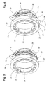
- eine perspektivische, vergrößerte Darstellung eines nach der 2K-Technologie in der ersten Stufe spritzgegossenen Anschlussflansches der Entnahmearmatur,
- Fig. 4
- eine perspektivische, vergrößerte Darstellung des nach der 2K-Technologie in der zweiten Stufe mit einem Erdungsleiter spritzgegossenen Anschlussflansches der Entnahmearmatur,
- Fig. 5
- die Stirnansicht des Anschlussflansches der Entnahmearmatur nach
Fig. 4 , - Fig. 6
- eine vergrößerte, perspektivische Darstellung des Auslaufbereichs des Transport- und Lagerbehälters mit der Entnahmearmatur,
- Fig. 7
- eine perspektivische Darstellung eines einteilig mit einem Erdungskabel spritzgegossenen Anschlussflansches aus einem elektrisch leitfähigen Kunststoffmaterial und
- Fig. 8
- die Stirnansicht des Anschlussflansches nach
Fig. 7 . - Der als Einweg- und Mehrwegbehälter einsetzbare Transport- und Lagerbehälter 1 für Flüssigkeiten nach
Fig. 1 weist als Hauptbauteile einen austauschbaren, quaderförmigen Innenbehälter 2 aus Kunststoff auf mit einer Stirnwand 3, einer Rückwand 4 und zwei Seitenwänden 5,6, einem unteren als Ablaufboden ausgebildeten Boden 7 und einem oberen Boden 8, einem an diesen angeformten, mit einem Deckel 10 verschließbaren Einfüllstutzen 9 und einem an einer Einwölbung 11 im unteren Abschnitt der Stirnwand 3 des Innenbehälters angeformten Entleerstutzen 12, der mit dem Innenbehälter 2 einteilig durch Blasformen hergestellt ist, zur Anbringung einer Entnahmearmatur 13, insbesondere eines Kugel- oder Klappenhahns, ferner einen als Gittermantel ausgebildeten Außenmantel 14 mit sich kreuzenden horizontalen und vertikalen Gitterstäben 15,16 aus Metall zur Aufnahme des Innenbehälters 2 sowie ein palettenartiges Untergestell 17 mit euronormgerechten Längen- und Breitenabmessungen zur Abstützung des Innenbehälters 2. - Das aus einem Polyethylen hoher Dichte (PE-HD) spritzgegossene Armaturengehäuse 18 der Entnahmearmatur 13 ist mit dem mit einem Innengewinde 19 versehenen Einlaufstutzen 20 auf einen ein entsprechendes Außengewinde 22 aufweisenden Anschlussflansch 21 aufgeschraubt und gegen diesen abgedichtet und der Anschlussflansch 21 ist zusammen mit der aufgeschraubten Entnahmearmatur 13 vorzugsweise durch Spiegelschweißen an dem Entleerstutzen 12 des Innenbehälters 2 angebracht. Der Anschlussflansch 21 ist als Spritzgussteil aus einem nichtleitenden Kunststoff, zum Beispiel Polyethylen, gefertigt (
Fig. 2 ). - Die Entnahmearmatur 13 ist mit einer elektrischen Erdung durch einen in den
Figuren 3 bis 5 dargestellten, einteilig ausgebildeten Erdungsleiter 23 aus einem elektrisch leitenden Kunststoff, beispielsweise Polyethylen mit Nanopartikeln, ausgestattet, der ein in die Innenwand 24 des Anschlussflansches 21 integriertes Ringsegment 25, einen in den Flanschring 26 des Anschlussflansches eingelassenen Verbindungssteg 27 sowie ein flexibles Kabel 28 zur elektrischen Verbindung des Anschlussflansches 21 des Armaturengehäuses 18 mit dem Untergestell 17 oder dem Außenmantel 14 des Transport- und Lagerbehälters 1 aufweist. - Gemäß
Fig. 6 wird der Erdungsleiter 23 des Anschlussflansches 21 des Armaturengehäuses 18 mit einer am freien Ende 29 des Kabels 28 ausgebildeten Lasche 30 an dem Blechboden 31 des Untergestells 17 des Transport- und Lagerbehälters 1 mittels einer Schraube 32 und einer Mutter 33 festgeschraubt. - Der in den
Figuren 3 bis 5 dargestellte Anschlussflansch 21 und der mit diesem einteilig ausgebildete Erdungsleiter 23 werden nach der 2K-Technologie mit einer Spritzgießmaschine hergestellt. - Zunächst wird in einem ersten Verfahrensschritt der Anschlussflansch 21 mit einer Aussparung 34 in der Innenwand 24 desselben für das Ringsegment 25 des Erdungsleiters 23, einer Nut 35 in dem Flanschring 26 des Anschlussflansches 21 für den Verbindungssteg 27 des Erdungsleiters 23 sowie einer ringsegmentförmigen Aussparung 36 und an diese anschließenden Nuten 37 in dem Außenrand 38 des Flanschringes 26 für einen Haltering 39 mit Haltestegen 40 und Abreißspitzen 41 für das Kabel 28 des Erdungsleiters 23 aus einem elektrisch nichtleitenden Kunststoffmaterial, beispielsweise einem Polyethylen hoher Dichte (PE-HD), spritzgegossen (
Figur 3 ). Anschließend wird mit der gleichen Spritzgießmaschine in einem zweiten Verfahrensschritt ein elektrisch leitendes Kunststoffmaterial, beispielsweise Polyethylen mit Nanopartikeln, zur Herstellung des Erdungsleiters mit dem Ringsegment 25, dem Verbindungssteg 27 und dem Kabel 28 auf den vorgefertigten Anschlussflansch 21 aufgespritzt (Figuren 4 und5 ). Nach dem Anschweißen des Anschlussflansches 21 mit dem auf diesen aufgeschraubten Armaturengehäuses 18 an den Entleerstutzen 12 des Innenbehälters 2 des Transport- und Lagerbehälters 1 wird das flexible Kabel 28 des Erdungsleiters 23 von den Abreißspitzen 41 der Haltestege 40 des Halterings 39 am Außenrand 38 des Flanschringes 26 des Anschlussflansches 21 abgetrennt. - Das in die Innenwand 24 des Anschlussflansches 21 integrierte Ringsegment 25 und die Befestigungslasche 30 am freien Ende 29 des Kabels 28 des Erdungsleiters 23 des Anschlussflansches 21 der Entnahmearmatur 13 werden mit einem Übermaß spritzgegossen und anschließend zur Verbesserung der elektrischen Leitfähigkeit abgeschält.
- Das Armaturengehäuse 18 und der Anschlussflansch 21 sind durch eine Originalitätssicherung miteinander verbunden, die durch einen Sicherungsclip 42 gebildet wird, der eine an den Flanschring 26 des Anschlussflansches 21 angespritzte Lasche 43 und eine entsprechende nicht dargestellte Lasche am Armaturengehäuse 18 miteinander verbindet (
Figuren 3 und6 ). - Ein weiterer in den
Figuren 7 und 8 dargestellter, als Gewindeflansch ausgebildeter Anschlussflansch 44, auf den gemäßFigur 2 das Armaturengehäuse 18 mit dem Einlaufstutzen 20 aufgeschraubt und mit dem das Armaturengehäuse 18 an den Entleerstutzen 12 des Innenbehälters 2 angeschweißt wird, ist einteilig mit einem begrenzt flexiblen Erdungskabel 45 aus einem elektrisch leitenden Kunststoffmaterial, beispielsweise einem Polyethylen hoher Dichte (PE-HD) mit Nanopartikeln, spritzgegossen. - Das eine Ende 46 des Erdungskabels 45 ist durch einen Übergang 47 an dem Flanschring 26 des Anschlussflansches 44 angebunden, und das andere Ende 48 des Erdungskabels 45 weist eine Befestigungslasche 49 zur Anbringung am Untergestell 17 oder Außenmantel 14 des Transport- und Lagerbehälters 1 auf.
- Der Kabelabschnitt 50 zwischen der Anbindung 47 und der Befestigungslasche 49 ist durch einen Abreißfilm 51 an den Flanschring 26 des Anschlussflansches 44 angebunden, derart, dass nach dem Anschweißen des Anschlussflansches 44 mit der Entnahmearmatur 13 an den Entleerstutzen 12 des Innenbehälters 2 der Kabelabschnitt 50 des Erdungskabels 45 zwischen Übergang 47 und Befestigungslasche 49 zur Anbringung des Kabels 45 mit der Befestigungslasche 49 an dem Untergestell 17 oder dem Außenmantel 14 des Transport- und Lagerbehälters 1 von dem Flanschring 26 des Anschlussflansches 44 abreißbar ist.
- Ein zylindrischer Abschnitt 52 der Innenwand 24 des Anschlussflansches 21 ist zur Verbesserung der elektrischen Leitfähigkeit des Anschlussflansches angeschält.
Claims (1)
- Entnahmearmatur mit einem Armaturengehäuse aus Kunststoff, insbesondere Klappen- oder Kugelhahn, für Transport- und Lagerbehälter für Flüssigkeiten, die mit einem Innenbehälter aus Kunststoff mit einem verschließbaren Einfüllstutzen und einem Entleerstutzen zum Anschluss der Entnahmearmatur, einem Außenmantel aus Metallgitter oder Blech sowie einem palettenartigen Untergestell aus Metall oder einem zumindest teilweise elektrisch leitenden Kunststoffmaterial zum Abstützen des Innenbehälters ausgestattet sind, und mit einem an das Armaturengehäuse angeschlossenen flexiblen Erdungskabel, gekennzeichnet durch einen als Gewindeflansch ausgebildeten Anschlussflansch (44) aus einem elektrisch leitenden Kunststoffmaterial, auf den das Armaturengehäuse (18) mit dem Einlaufstutzen (20) aufgeschraubt und mit dem das Armaturengehäuse (18) an den Entleerstutzen (12) des Innenbehälters (2) angeschweißt wird, wobei das Erdungskabel (45) als ein einteilig mit dem Anschlussflansch (21) spritzgegossenes Erdungskabel ausgebildet ist, dessen eines Ende (46) durch einen Übergang (47) an den Flanschring (26) des Anschlussflansches (44) angebunden ist und dessen anderes Ende (48) eine Befestigungslasche (49) zur Anbringung am Untergestell (17) oder Außenmantel (14) des Transport- und Lagerbehälters (1) aufweist, wobei der Kabelabschnitt (50) zwischen dem Übergang (47) und der Befestigungslasche (49) durch einen Abreißfilm (51) an den Flanschring (26) des Anschlussflansches (44) angebunden ist, derart, dass nach dem Anschweißen des Anschlussflansches(44) mit der Entnahmearmatur (13) an den Entleerstutzen (12) des Innenbehälters (2) der Kabelabschnitt (50) des Erdungskabels (45) zwischen Übergang (47) und Befestigungslasche (49) zur Anbringung des Kabels (45) mit der Befestigungslasche (49) an dem Untergestell (17) oder dem Außenmantel (14) des Transport- und Lagerbehälters (1) von dem Flanschring (26) des Anschlussflansches (44) abreißbar ist.
Applications Claiming Priority (2)
| Application Number | Priority Date | Filing Date | Title |
|---|---|---|---|
| DE102009016451A DE102009016451B3 (de) | 2009-04-04 | 2009-04-04 | Entnahmearmatur mit einem Armaturengehäuse aus Kunststoff für Transport- und Lagerbehälter für Flüssigkeiten und Verfahren zur Herstellung des elektrisch geerdeten Anschlussflansches zur Befestigung der Entnahmearmatur an dem Entleerstutzen des Innenbehälters des Transport- und Lagerbehälters |
| EP10158482A EP2239206B1 (de) | 2009-04-04 | 2010-03-30 | Entnahmearmatur mit einem Armaturengehäuse aus Kunststoff für Transport- und Lagerbehälter für Flüssigkeiten und Verfahren zur Herstellung des elektrisch geerdeten Anschlussflansches zur Befestigung der Entnahmearmatur an dem Entleerstutzen des Innenbehälters des Transport- und Lagerbehälters |
Related Parent Applications (2)
| Application Number | Title | Priority Date | Filing Date |
|---|---|---|---|
| EP10158482A Division EP2239206B1 (de) | 2009-04-04 | 2010-03-30 | Entnahmearmatur mit einem Armaturengehäuse aus Kunststoff für Transport- und Lagerbehälter für Flüssigkeiten und Verfahren zur Herstellung des elektrisch geerdeten Anschlussflansches zur Befestigung der Entnahmearmatur an dem Entleerstutzen des Innenbehälters des Transport- und Lagerbehälters |
| EP10158482.9 Division | 2010-03-30 |
Publications (2)
| Publication Number | Publication Date |
|---|---|
| EP2388207A1 true EP2388207A1 (de) | 2011-11-23 |
| EP2388207B1 EP2388207B1 (de) | 2012-08-29 |
Family
ID=42313004
Family Applications (2)
| Application Number | Title | Priority Date | Filing Date |
|---|---|---|---|
| EP10158482A Active EP2239206B1 (de) | 2009-04-04 | 2010-03-30 | Entnahmearmatur mit einem Armaturengehäuse aus Kunststoff für Transport- und Lagerbehälter für Flüssigkeiten und Verfahren zur Herstellung des elektrisch geerdeten Anschlussflansches zur Befestigung der Entnahmearmatur an dem Entleerstutzen des Innenbehälters des Transport- und Lagerbehälters |
| EP11177802A Active EP2388207B1 (de) | 2009-04-04 | 2010-03-30 | Entnahmearmatur mit einem Armaturengehäuse aus Kunststoff für Transport- und Lagerbehälter für Flüssigkeiten |
Family Applications Before (1)
| Application Number | Title | Priority Date | Filing Date |
|---|---|---|---|
| EP10158482A Active EP2239206B1 (de) | 2009-04-04 | 2010-03-30 | Entnahmearmatur mit einem Armaturengehäuse aus Kunststoff für Transport- und Lagerbehälter für Flüssigkeiten und Verfahren zur Herstellung des elektrisch geerdeten Anschlussflansches zur Befestigung der Entnahmearmatur an dem Entleerstutzen des Innenbehälters des Transport- und Lagerbehälters |
Country Status (14)
| Country | Link |
|---|---|
| US (1) | US8477471B2 (de) |
| EP (2) | EP2239206B1 (de) |
| JP (1) | JP5175895B2 (de) |
| KR (1) | KR101284459B1 (de) |
| CN (1) | CN101857122B (de) |
| AR (1) | AR076004A1 (de) |
| AT (1) | ATE556830T1 (de) |
| AU (1) | AU2010201234B2 (de) |
| BR (1) | BRPI1001003B1 (de) |
| DE (1) | DE102009016451B3 (de) |
| ES (2) | ES2387641T3 (de) |
| MX (1) | MX2010003482A (de) |
| MY (2) | MY160355A (de) |
| RU (1) | RU2407690C1 (de) |
Families Citing this family (9)
| Publication number | Priority date | Publication date | Assignee | Title |
|---|---|---|---|---|
| DE102010039328A1 (de) | 2010-08-13 | 2012-02-16 | Protechna S.A. | Entnahmearmatur für einen Transport- und Lagerbehälter für Flüssigkeiten sowie Transport- und Lagerbehälter mit einer solchen Entnahmearmatur |
| DE102010041545B4 (de) * | 2010-09-28 | 2021-07-01 | Protechna S.A. | Transport- und Lagerbehälter für Flüssigkeiten |
| DE202013000624U1 (de) * | 2012-09-21 | 2013-03-07 | Mauser-Werke Gmbh | Palettencontainer |
| DE102012022129B4 (de) * | 2012-11-13 | 2024-10-10 | Kautex Textron Gmbh & Co. Kg | Elektrisch Leitfähiges Mundstück |
| CN104097828A (zh) * | 2013-04-12 | 2014-10-15 | 上海舒龙包装材料有限公司 | 一种用于盛装易燃液体的防爆桶及其桶体的加工工艺 |
| CN103754465A (zh) * | 2014-01-24 | 2014-04-30 | 上海福将塑胶工业集团有限公司 | 复合式中型散装容器塑料内容器及其制备方法 |
| EP3684706B1 (de) * | 2017-09-22 | 2021-12-08 | Mauser-Werke GmbH | Inliner |
| KR102223835B1 (ko) * | 2019-05-14 | 2021-03-08 | 엘지전자 주식회사 | 음료 제조기 |
| DE202022101418U1 (de) | 2022-03-17 | 2023-06-20 | Bodo Richter | Transportbehälter mt Spannscheibe |
Citations (4)
| Publication number | Priority date | Publication date | Assignee | Title |
|---|---|---|---|---|
| EP0949159A2 (de) * | 1998-04-06 | 1999-10-13 | Protechna S.A. | Transport- und Lagerbehälter für Flüssigkeiten |
| EP1319608A1 (de) * | 2001-12-13 | 2003-06-18 | Roth Werke GmbH | Behälter, insbesondere Paletteninnenbehälter |
| EP2008946A1 (de) * | 2007-06-28 | 2008-12-31 | Daviplast - Servicos de Consultoria, Sociedade Unipessoal LDA. | Behälter für Flüssigkeiten |
| EP2157028A1 (de) * | 2008-08-20 | 2010-02-24 | Protechna S.A. | Entnahmearmatur mit einem Armaturengehäuse aus Kunststoff für Transport- und Lagerbehälter für Flüssigkeiten |
Family Cites Families (13)
| Publication number | Priority date | Publication date | Assignee | Title |
|---|---|---|---|---|
| DE10216960B4 (de) * | 2002-04-17 | 2005-07-21 | Schneider, Ekkehard, Dipl.-Ing. | Gegen elektrostatische Aufladung geschützte Behälteranordnung für fliessfähige Stoffe |
| US7042695B2 (en) * | 2002-04-23 | 2006-05-09 | Mauser-Werke Gmbh & Co. Kg | Plastic container with electric dissipation capability |
| DE10241286B4 (de) * | 2002-09-03 | 2004-07-22 | Rasmussen Gmbh | Bauteil zum Verbinden einer Fluidleitung mit einer Öffnung eines Kunststoff aufweisenden Behälters oder zum Verschließen der Öffnung |
| DE10242954A1 (de) * | 2002-09-17 | 2004-03-25 | Protechna S.A. | Transport- und Lagerbehälter für Flüssigkeiten |
| DE10242956B4 (de) * | 2002-09-17 | 2004-07-15 | Protechna S.A. | Transport- und Lagerbehälter für Flüssigkeiten und Verfahren zur Herstellung des Kunststoff-Innenbehälters des Transport- und Lagerbehälters |
| DE10313481B4 (de) * | 2003-03-26 | 2005-07-07 | Protechna S.A. | Transport- und Lagerbehälter für Flüssigkeiten |
| DE10344962B3 (de) * | 2003-09-27 | 2005-04-07 | Protechna S.A. | Entnahmearmatur aus Kunststoff für Transport- und Lagerbehälter für Flüssigkeiten |
| ZA200409370B (en) * | 2003-12-17 | 2005-07-13 | Protechna Sa | Originality safeguard for transportation and storage containers. |
| DK1718544T3 (da) * | 2004-02-27 | 2009-04-27 | Mauser Werke Gmbh | Pallecontainer |
| KR100530122B1 (ko) * | 2004-05-10 | 2005-11-21 | 기아자동차주식회사 | 차량 연료 주입구 캡의 정전기 방지 장치 |
| DE102004039961A1 (de) * | 2004-08-18 | 2006-03-09 | Protechna S.A. | Verfahren zur Herstellung einer als Kunststoff-Spritzgußteil gefertigten Entnahmearmatur für Transport- und Lagerbehälter aus Kunststoff oder Metall für Flüssigkeiten |
| DE102006020447B4 (de) * | 2006-05-03 | 2008-01-31 | Sotralentz Packaging S.A.S. | Absperrorgan für einen Behälter, insbesondere Palettenbehälter |
| DE202006020793U1 (de) | 2006-09-06 | 2010-03-11 | Mauser-Werke Gmbh | Palettencontainer |
-
2009
- 2009-04-04 DE DE102009016451A patent/DE102009016451B3/de not_active Expired - Fee Related
-
2010
- 2010-03-26 AU AU2010201234A patent/AU2010201234B2/en active Active
- 2010-03-29 MX MX2010003482A patent/MX2010003482A/es active IP Right Grant
- 2010-03-30 ES ES10158482T patent/ES2387641T3/es active Active
- 2010-03-30 AT AT10158482T patent/ATE556830T1/de active
- 2010-03-30 ES ES11177802T patent/ES2394286T3/es active Active
- 2010-03-30 EP EP10158482A patent/EP2239206B1/de active Active
- 2010-03-30 EP EP11177802A patent/EP2388207B1/de active Active
- 2010-03-31 AR ARP100101046A patent/AR076004A1/es active IP Right Grant
- 2010-03-31 MY MYPI2010001414A patent/MY160355A/en unknown
- 2010-03-31 MY MYPI2015002804A patent/MY182227A/en unknown
- 2010-04-01 US US12/752,852 patent/US8477471B2/en active Active
- 2010-04-01 RU RU2010112496/12A patent/RU2407690C1/ru active
- 2010-04-02 KR KR1020100030213A patent/KR101284459B1/ko active Active
- 2010-04-02 CN CN2010101626211A patent/CN101857122B/zh active Active
- 2010-04-05 JP JP2010087190A patent/JP5175895B2/ja active Active
- 2010-04-06 BR BRPI1001003-3A patent/BRPI1001003B1/pt active IP Right Grant
Patent Citations (4)
| Publication number | Priority date | Publication date | Assignee | Title |
|---|---|---|---|---|
| EP0949159A2 (de) * | 1998-04-06 | 1999-10-13 | Protechna S.A. | Transport- und Lagerbehälter für Flüssigkeiten |
| EP1319608A1 (de) * | 2001-12-13 | 2003-06-18 | Roth Werke GmbH | Behälter, insbesondere Paletteninnenbehälter |
| EP2008946A1 (de) * | 2007-06-28 | 2008-12-31 | Daviplast - Servicos de Consultoria, Sociedade Unipessoal LDA. | Behälter für Flüssigkeiten |
| EP2157028A1 (de) * | 2008-08-20 | 2010-02-24 | Protechna S.A. | Entnahmearmatur mit einem Armaturengehäuse aus Kunststoff für Transport- und Lagerbehälter für Flüssigkeiten |
Also Published As
| Publication number | Publication date |
|---|---|
| MY182227A (en) | 2021-01-18 |
| AU2010201234A1 (en) | 2010-10-21 |
| JP2010241507A (ja) | 2010-10-28 |
| EP2239206A2 (de) | 2010-10-13 |
| KR101284459B1 (ko) | 2013-07-17 |
| BRPI1001003B1 (pt) | 2024-03-12 |
| MY160355A (en) | 2017-02-28 |
| ES2394286T3 (es) | 2013-01-30 |
| ATE556830T1 (de) | 2012-05-15 |
| RU2407690C1 (ru) | 2010-12-27 |
| MX2010003482A (es) | 2010-10-05 |
| ES2387641T3 (es) | 2012-09-27 |
| EP2239206A3 (de) | 2011-02-23 |
| BRPI1001003A2 (pt) | 2011-06-21 |
| JP5175895B2 (ja) | 2013-04-03 |
| US20100252765A1 (en) | 2010-10-07 |
| AU2010201234B2 (en) | 2013-04-04 |
| CN101857122A (zh) | 2010-10-13 |
| DE102009016451B3 (de) | 2011-01-20 |
| CN101857122B (zh) | 2013-01-23 |
| KR20100110742A (ko) | 2010-10-13 |
| AR076004A1 (es) | 2011-05-11 |
| US8477471B2 (en) | 2013-07-02 |
| EP2388207B1 (de) | 2012-08-29 |
| EP2239206B1 (de) | 2012-05-09 |
Similar Documents
| Publication | Publication Date | Title |
|---|---|---|
| EP2388207B1 (de) | Entnahmearmatur mit einem Armaturengehäuse aus Kunststoff für Transport- und Lagerbehälter für Flüssigkeiten | |
| EP2418168B1 (de) | Entnahmearmatur für einen Transport- und Lagerbehälter für Flüssigkeiten sowie Transport- und Lagerbehälter mit einer solchen Entnahmearmatur | |
| EP2157028B1 (de) | Entnahmearmatur mit einem Armaturengehäuse aus Kunststoff für Transport- und Lagerbehälter für Flüssigkeiten | |
| DE4341646A1 (de) | Gewindestutzen an Öffnungen von Flüssigkeitsbehältern aus Blech | |
| DE102016114453B4 (de) | Gehäuse für eine elektrische Einrichtung und Verfahren zur Herstellung eines solchen Gehäuses | |
| DE3002651C2 (de) | ||
| DE102012022129B4 (de) | Elektrisch Leitfähiges Mundstück | |
| WO2008142016A1 (de) | Elektrische anschlusseinrichtung für photovoltaische module | |
| EP1422161B1 (de) | Transport- und Lagerbehälter für Flüssigkeiten | |
| EP1768201B1 (de) | Bleibatterie und Kunststoff-Batteriedeckel hierzu | |
| EP3540885A1 (de) | Installationsdose | |
| WO2015078460A1 (de) | Elektronische baugruppe mit einem gehäuse aus einem kunststoffteil und einem metallteil | |
| DE102011087353A1 (de) | Halbleitervorrichtung | |
| EP2863041A1 (de) | Tank | |
| EP2704544A2 (de) | Sensoranordnung | |
| DE202006020793U1 (de) | Palettencontainer | |
| EP1095430B1 (de) | Verfahren zum schutz von kabellitzen | |
| EP1319608B1 (de) | Behälter, insbesondere Paletteninnenbehälter | |
| DE19530526A1 (de) | Kraftstoffilter mit einem elektrisch leitfähigen Gehäuse für insbesondere Kraftfahrzeuge | |
| DE102006062795B4 (de) | Hochstromkabel für Fahrzeuge sowie Kabelkanal zum elektrisch isolierenden Aufnehmen eines solchen Hochstromkabels | |
| DE102009016386B4 (de) | Batterie mit einem Gehäuse | |
| DE102015207712B4 (de) | Fördermodul mit integriertem Widerstand | |
| EP3683893B1 (de) | Elektrisches bauteil,verfahren zu seiner herstellung, und tragestruktur | |
| DE102023105626B4 (de) | Leistungselektrisches Gerät | |
| EP1016108B1 (de) | Elektrischer kondensator |
Legal Events
| Date | Code | Title | Description |
|---|---|---|---|
| 17P | Request for examination filed |
Effective date: 20110921 |
|
| AC | Divisional application: reference to earlier application |
Ref document number: 2239206 Country of ref document: EP Kind code of ref document: P |
|
| AK | Designated contracting states |
Kind code of ref document: A1 Designated state(s): AT BE BG CH CY CZ DE DK EE ES FI FR GB GR HR HU IE IS IT LI LT LU LV MC MK MT NL NO PL PT RO SE SI SK SM TR |
|
| AX | Request for extension of the european patent |
Extension state: AL BA ME RS |
|
| PUAI | Public reference made under article 153(3) epc to a published international application that has entered the european phase |
Free format text: ORIGINAL CODE: 0009012 |
|
| GRAP | Despatch of communication of intention to grant a patent |
Free format text: ORIGINAL CODE: EPIDOSNIGR1 |
|
| RIC1 | Information provided on ipc code assigned before grant |
Ipc: B29C 45/16 20060101ALI20120306BHEP Ipc: B29C 45/00 20060101ALI20120306BHEP Ipc: B65D 77/04 20060101AFI20120306BHEP |
|
| RIN1 | Information on inventor provided before grant (corrected) |
Inventor name: DER ERFINDER HAT AUF SEINE NENNUNG VERZICHTET. |
|
| GRAS | Grant fee paid |
Free format text: ORIGINAL CODE: EPIDOSNIGR3 |
|
| GRAA | (expected) grant |
Free format text: ORIGINAL CODE: 0009210 |
|
| AC | Divisional application: reference to earlier application |
Ref document number: 2239206 Country of ref document: EP Kind code of ref document: P |
|
| AK | Designated contracting states |
Kind code of ref document: B1 Designated state(s): AT BE BG CH CY CZ DE DK EE ES FI FR GB GR HR HU IE IS IT LI LT LU LV MC MK MT NL NO PL PT RO SE SI SK SM TR |
|
| REG | Reference to a national code |
Ref country code: GB Ref legal event code: FG4D Free format text: NOT ENGLISH |
|
| REG | Reference to a national code |
Ref country code: CH Ref legal event code: EP |
|
| REG | Reference to a national code |
Ref country code: AT Ref legal event code: REF Ref document number: 572936 Country of ref document: AT Kind code of ref document: T Effective date: 20120915 |
|
| REG | Reference to a national code |
Ref country code: IE Ref legal event code: FG4D Free format text: LANGUAGE OF EP DOCUMENT: GERMAN |
|
| REG | Reference to a national code |
Ref country code: SE Ref legal event code: TRGR |
|
| REG | Reference to a national code |
Ref country code: DE Ref legal event code: R096 Ref document number: 502010001194 Country of ref document: DE Effective date: 20121018 |
|
| REG | Reference to a national code |
Ref country code: NL Ref legal event code: T3 |
|
| REG | Reference to a national code |
Ref country code: LT Ref legal event code: MG4D Effective date: 20120829 |
|
| REG | Reference to a national code |
Ref country code: ES Ref legal event code: FG2A Ref document number: 2394286 Country of ref document: ES Kind code of ref document: T3 Effective date: 20130130 |
|
| PG25 | Lapsed in a contracting state [announced via postgrant information from national office to epo] |
Ref country code: IS Free format text: LAPSE BECAUSE OF FAILURE TO SUBMIT A TRANSLATION OF THE DESCRIPTION OR TO PAY THE FEE WITHIN THE PRESCRIBED TIME-LIMIT Effective date: 20121229 Ref country code: NO Free format text: LAPSE BECAUSE OF FAILURE TO SUBMIT A TRANSLATION OF THE DESCRIPTION OR TO PAY THE FEE WITHIN THE PRESCRIBED TIME-LIMIT Effective date: 20121129 Ref country code: FI Free format text: LAPSE BECAUSE OF FAILURE TO SUBMIT A TRANSLATION OF THE DESCRIPTION OR TO PAY THE FEE WITHIN THE PRESCRIBED TIME-LIMIT Effective date: 20120829 Ref country code: LT Free format text: LAPSE BECAUSE OF FAILURE TO SUBMIT A TRANSLATION OF THE DESCRIPTION OR TO PAY THE FEE WITHIN THE PRESCRIBED TIME-LIMIT Effective date: 20120829 Ref country code: HR Free format text: LAPSE BECAUSE OF FAILURE TO SUBMIT A TRANSLATION OF THE DESCRIPTION OR TO PAY THE FEE WITHIN THE PRESCRIBED TIME-LIMIT Effective date: 20120829 |
|
| PG25 | Lapsed in a contracting state [announced via postgrant information from national office to epo] |
Ref country code: LV Free format text: LAPSE BECAUSE OF FAILURE TO SUBMIT A TRANSLATION OF THE DESCRIPTION OR TO PAY THE FEE WITHIN THE PRESCRIBED TIME-LIMIT Effective date: 20120829 Ref country code: SI Free format text: LAPSE BECAUSE OF FAILURE TO SUBMIT A TRANSLATION OF THE DESCRIPTION OR TO PAY THE FEE WITHIN THE PRESCRIBED TIME-LIMIT Effective date: 20120829 Ref country code: PT Free format text: LAPSE BECAUSE OF FAILURE TO SUBMIT A TRANSLATION OF THE DESCRIPTION OR TO PAY THE FEE WITHIN THE PRESCRIBED TIME-LIMIT Effective date: 20121231 |
|
| PG25 | Lapsed in a contracting state [announced via postgrant information from national office to epo] |
Ref country code: EE Free format text: LAPSE BECAUSE OF FAILURE TO SUBMIT A TRANSLATION OF THE DESCRIPTION OR TO PAY THE FEE WITHIN THE PRESCRIBED TIME-LIMIT Effective date: 20120829 Ref country code: RO Free format text: LAPSE BECAUSE OF FAILURE TO SUBMIT A TRANSLATION OF THE DESCRIPTION OR TO PAY THE FEE WITHIN THE PRESCRIBED TIME-LIMIT Effective date: 20120829 Ref country code: DK Free format text: LAPSE BECAUSE OF FAILURE TO SUBMIT A TRANSLATION OF THE DESCRIPTION OR TO PAY THE FEE WITHIN THE PRESCRIBED TIME-LIMIT Effective date: 20120829 Ref country code: CZ Free format text: LAPSE BECAUSE OF FAILURE TO SUBMIT A TRANSLATION OF THE DESCRIPTION OR TO PAY THE FEE WITHIN THE PRESCRIBED TIME-LIMIT Effective date: 20120829 |
|
| PG25 | Lapsed in a contracting state [announced via postgrant information from national office to epo] |
Ref country code: SK Free format text: LAPSE BECAUSE OF FAILURE TO SUBMIT A TRANSLATION OF THE DESCRIPTION OR TO PAY THE FEE WITHIN THE PRESCRIBED TIME-LIMIT Effective date: 20120829 Ref country code: PL Free format text: LAPSE BECAUSE OF FAILURE TO SUBMIT A TRANSLATION OF THE DESCRIPTION OR TO PAY THE FEE WITHIN THE PRESCRIBED TIME-LIMIT Effective date: 20120829 |
|
| PLBE | No opposition filed within time limit |
Free format text: ORIGINAL CODE: 0009261 |
|
| STAA | Information on the status of an ep patent application or granted ep patent |
Free format text: STATUS: NO OPPOSITION FILED WITHIN TIME LIMIT |
|
| PG25 | Lapsed in a contracting state [announced via postgrant information from national office to epo] |
Ref country code: BG Free format text: LAPSE BECAUSE OF FAILURE TO SUBMIT A TRANSLATION OF THE DESCRIPTION OR TO PAY THE FEE WITHIN THE PRESCRIBED TIME-LIMIT Effective date: 20121129 |
|
| 26N | No opposition filed |
Effective date: 20130530 |
|
| REG | Reference to a national code |
Ref country code: DE Ref legal event code: R097 Ref document number: 502010001194 Country of ref document: DE Effective date: 20130530 |
|
| PG25 | Lapsed in a contracting state [announced via postgrant information from national office to epo] |
Ref country code: MC Free format text: LAPSE BECAUSE OF NON-PAYMENT OF DUE FEES Effective date: 20130331 |
|
| PG25 | Lapsed in a contracting state [announced via postgrant information from national office to epo] |
Ref country code: CY Free format text: LAPSE BECAUSE OF FAILURE TO SUBMIT A TRANSLATION OF THE DESCRIPTION OR TO PAY THE FEE WITHIN THE PRESCRIBED TIME-LIMIT Effective date: 20120829 |
|
| REG | Reference to a national code |
Ref country code: IE Ref legal event code: MM4A |
|
| PG25 | Lapsed in a contracting state [announced via postgrant information from national office to epo] |
Ref country code: IE Free format text: LAPSE BECAUSE OF NON-PAYMENT OF DUE FEES Effective date: 20130330 |
|
| PG25 | Lapsed in a contracting state [announced via postgrant information from national office to epo] |
Ref country code: MT Free format text: LAPSE BECAUSE OF FAILURE TO SUBMIT A TRANSLATION OF THE DESCRIPTION OR TO PAY THE FEE WITHIN THE PRESCRIBED TIME-LIMIT Effective date: 20120829 |
|
| PG25 | Lapsed in a contracting state [announced via postgrant information from national office to epo] |
Ref country code: SM Free format text: LAPSE BECAUSE OF FAILURE TO SUBMIT A TRANSLATION OF THE DESCRIPTION OR TO PAY THE FEE WITHIN THE PRESCRIBED TIME-LIMIT Effective date: 20120829 |
|
| PG25 | Lapsed in a contracting state [announced via postgrant information from national office to epo] |
Ref country code: HU Free format text: LAPSE BECAUSE OF FAILURE TO SUBMIT A TRANSLATION OF THE DESCRIPTION OR TO PAY THE FEE WITHIN THE PRESCRIBED TIME-LIMIT; INVALID AB INITIO Effective date: 20100330 Ref country code: MK Free format text: LAPSE BECAUSE OF FAILURE TO SUBMIT A TRANSLATION OF THE DESCRIPTION OR TO PAY THE FEE WITHIN THE PRESCRIBED TIME-LIMIT Effective date: 20120829 Ref country code: LU Free format text: LAPSE BECAUSE OF NON-PAYMENT OF DUE FEES Effective date: 20130330 |
|
| PG25 | Lapsed in a contracting state [announced via postgrant information from national office to epo] |
Ref country code: GR Free format text: LAPSE BECAUSE OF NON-PAYMENT OF DUE FEES Effective date: 20120829 |
|
| REG | Reference to a national code |
Ref country code: FR Ref legal event code: PLFP Year of fee payment: 7 |
|
| REG | Reference to a national code |
Ref country code: AT Ref legal event code: MM01 Ref document number: 572936 Country of ref document: AT Kind code of ref document: T Effective date: 20150330 |
|
| PG25 | Lapsed in a contracting state [announced via postgrant information from national office to epo] |
Ref country code: AT Free format text: LAPSE BECAUSE OF NON-PAYMENT OF DUE FEES Effective date: 20150330 |
|
| REG | Reference to a national code |
Ref country code: FR Ref legal event code: PLFP Year of fee payment: 8 |
|
| REG | Reference to a national code |
Ref country code: FR Ref legal event code: PLFP Year of fee payment: 9 |
|
| P01 | Opt-out of the competence of the unified patent court (upc) registered |
Effective date: 20230526 |
|
| PGFP | Annual fee paid to national office [announced via postgrant information from national office to epo] |
Ref country code: DE Payment date: 20250515 Year of fee payment: 16 |
|
| PGFP | Annual fee paid to national office [announced via postgrant information from national office to epo] |
Ref country code: ES Payment date: 20250416 Year of fee payment: 16 |
|
| PGFP | Annual fee paid to national office [announced via postgrant information from national office to epo] |
Ref country code: IT Payment date: 20250331 Year of fee payment: 16 |
|
| PGFP | Annual fee paid to national office [announced via postgrant information from national office to epo] |
Ref country code: CH Payment date: 20250625 Year of fee payment: 16 |
|
| PGFP | Annual fee paid to national office [announced via postgrant information from national office to epo] |
Ref country code: SE Payment date: 20260323 Year of fee payment: 17 |
|
| PGFP | Annual fee paid to national office [announced via postgrant information from national office to epo] |
Ref country code: GB Payment date: 20260324 Year of fee payment: 17 |
|
| PGFP | Annual fee paid to national office [announced via postgrant information from national office to epo] |
Ref country code: BE Payment date: 20260323 Year of fee payment: 17 |
|
| PGFP | Annual fee paid to national office [announced via postgrant information from national office to epo] |
Ref country code: NL Payment date: 20260323 Year of fee payment: 17 |
|
| PGFP | Annual fee paid to national office [announced via postgrant information from national office to epo] |
Ref country code: FR Payment date: 20260324 Year of fee payment: 17 |
|
| PGFP | Annual fee paid to national office [announced via postgrant information from national office to epo] |
Ref country code: TR Payment date: 20260325 Year of fee payment: 17 |