EP2388376A2 - Pont - Google Patents
Pont Download PDFInfo
- Publication number
- EP2388376A2 EP2388376A2 EP11003549A EP11003549A EP2388376A2 EP 2388376 A2 EP2388376 A2 EP 2388376A2 EP 11003549 A EP11003549 A EP 11003549A EP 11003549 A EP11003549 A EP 11003549A EP 2388376 A2 EP2388376 A2 EP 2388376A2
- Authority
- EP
- European Patent Office
- Prior art keywords
- web
- support profiles
- bridge
- belt
- profiles
- Prior art date
- Legal status (The legal status is an assumption and is not a legal conclusion. Google has not performed a legal analysis and makes no representation as to the accuracy of the status listed.)
- Withdrawn
Links
- 238000003466 welding Methods 0.000 description 7
- 238000003892 spreading Methods 0.000 description 3
- 229910052782 aluminium Inorganic materials 0.000 description 2
- 230000006835 compression Effects 0.000 description 2
- 238000007906 compression Methods 0.000 description 2
- 238000004519 manufacturing process Methods 0.000 description 2
- 229910052751 metal Inorganic materials 0.000 description 2
- 239000002184 metal Substances 0.000 description 2
- XAGFODPZIPBFFR-UHFFFAOYSA-N aluminium Chemical compound [Al] XAGFODPZIPBFFR-UHFFFAOYSA-N 0.000 description 1
- 238000005452 bending Methods 0.000 description 1
- 230000015572 biosynthetic process Effects 0.000 description 1
- 239000000969 carrier Substances 0.000 description 1
- 238000010276 construction Methods 0.000 description 1
- 230000008878 coupling Effects 0.000 description 1
- 238000010168 coupling process Methods 0.000 description 1
- 238000005859 coupling reaction Methods 0.000 description 1
- 210000001331 nose Anatomy 0.000 description 1
- 230000002093 peripheral effect Effects 0.000 description 1
- 238000002360 preparation method Methods 0.000 description 1
- 239000011150 reinforced concrete Substances 0.000 description 1
- 230000002787 reinforcement Effects 0.000 description 1
- 238000000926 separation method Methods 0.000 description 1
- 230000035939 shock Effects 0.000 description 1
- 230000008719 thickening Effects 0.000 description 1
Images



Classifications
-
- E—FIXED CONSTRUCTIONS
- E01—CONSTRUCTION OF ROADS, RAILWAYS, OR BRIDGES
- E01D—CONSTRUCTION OF BRIDGES, ELEVATED ROADWAYS OR VIADUCTS; ASSEMBLY OF BRIDGES
- E01D19/00—Structural or constructional details of bridges
- E01D19/10—Railings; Protectors against smoke or gases, e.g. of locomotives; Maintenance travellers; Fastening of pipes or cables to bridges
- E01D19/103—Parapets, railings ; Guard barriers or road-bridges
-
- E—FIXED CONSTRUCTIONS
- E01—CONSTRUCTION OF ROADS, RAILWAYS, OR BRIDGES
- E01D—CONSTRUCTION OF BRIDGES, ELEVATED ROADWAYS OR VIADUCTS; ASSEMBLY OF BRIDGES
- E01D2/00—Bridges characterised by the cross-section of their bearing spanning structure
- E01D2/04—Bridges characterised by the cross-section of their bearing spanning structure of the box-girder type
Definitions
- the invention relates to a bridge with a top chord, a bottom chord and at least one belt connecting web connecting the top chord to the bottom chord.
- Bridges with a top chord, a bottom chord and at least one belt connecting web forming the top chord with the bottom chord are known in particular in the form of hollow box bridges.
- at least one hollow chamber extending in the longitudinal direction of the bridge is formed between at least two belt connecting webs.
- Such hollow box bridges are known in particular in the form of reinforced concrete bridges.
- the object of the invention is to provide a simple, in particular modular, formable bridge of the type mentioned. According to the invention, this is achieved by a bridge having the features of claim 1.
- the upper belt and / or the lower belt preferably both the upper belt and the lower belt, seen in cross section through the bridge a plurality of adjacent and interconnected support profiles or is formed from this total.
- adjacent and interconnected support profiles for example, a lying above or below the support profiles, over the width of the bridge continuous layer could be present.
- the adjacent and interconnected support profiles have at least some, preferably all, an upper web, a lower web and at least one of the upper web with the lower web connecting connecting web on.
- the bridge can be easily formed, in particular modular.
- the support profiles of the upper belt and / or the lower belt which are adjacent to one another and are interconnected in cross section through the bridge, preferably extend together over at least 90% of the total width of the bridge.
- On both sides next to these interconnected support profiles can be arranged, for example, extending between the upper flange and the lower flange cover profiles.
- the bridge can thus be referred to as a box girder bridge.
- the support profiles are conveniently made of metal, preferably aluminum.
- the mutual connection of at least some of the support profiles of the upper belt and / or the lower belt viewed in cross section through the bridge comprises a latching connection.
- connection to the respective at least one adjacent support profile comprises a latching connection.
- a preferred embodiment for a latching connection between adjacent in cross-section through the bridge supporting profiles of the upper belt and / or the lower chord provides that at least one, particularly preferably only one, the two connected by the latching connection supporting profiles in the direction of the other of the two connected by the locking connection support profiles cantilevered portions of the upper and lower webs, which are engaged in the other of the two connected support profiles in a locking seat.
- all latching connections of adjacent supporting profiles of the upper belt and / or the lower belt are formed in this form.
- the force required for latching is achieved by an elastic spreading apart or by an elastic compression of the projecting portions of the upper and lower webs.
- the connection with the adjacent support profile takes place in the region of the free ends of the projecting portions of the upper and lower webs.
- the projecting portions of the upper and lower webs on locking lugs which engage in locking recesses of the locking seat.
- a reverse training is possible in which the locking lugs are formed on the locking seat and the locking recesses on the upper and lower webs.
- the locking lugs are preferably (in cross section through the bridge or the support profile seen) wedge-shaped and the locking recesses have a corresponding V-shape.
- the support profiles connected by the latching connections are preferably additionally welded together. Due to the latching connection, the correct positioning between the two support profiles to be connected is achieved during assembly.
- the connection is fixed.
- the projecting portions of the upper and lower web are connected to each other via at least one screw. By this screw the distance between the upper and the lower web can be changed, whereby the inclination of the upper web changed. This allows the vertical alignment of the railing to be carried out.
- the trained on the upper web seat can for example be formed by a recess into which a foot plate of the railing is inserted. This is braced with at least one clamping screw with the upper web.
- the foot plate is located only in two-sided edge regions (based on the cross section through the bridge) on the bottom of the recess and in a middle region between the bottom of the recess is formed recessed, so that a cavity forms below the base plate.
- the at least one clamping screw engages the foot plate in the region of this cavity.
- At least a part, preferably all, of the upper web to the lower web connecting connecting webs of the support profiles are advantageously aligned vertically.
- At least one of the upper belt and the lower flange of the bridge connecting belt connecting webs is advantageously aligned vertically, preferably at least two vertically oriented belt connecting webs are present.
- at least the upper webs of the central support profiles of the upper belt in cross section through the bridge at least substantially a majority of their width extension at least substantially horizontally ("substantially horizontal” is intended to include deviations from the horizontal of up to +/- 10 °).
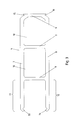
- FIG. 1 to 5 an embodiment of a bridge according to the invention is shown.
- the bridge comprises a top flange 1, a bottom flange 2 and between the top flange 1 and the bottom flange 2 extending belt connecting webs 3.
- two vertically extending belt connecting webs 3 are present.
- further vertically and / or obliquely extending belt connecting webs 3 may be provided.
- the upper surface of the upper belt 1 can directly form the roadway and / or the sidewalk of the bridge. At least one further layer could also be arranged on the upper belt 1, the upper surface of which forms the roadway and / or the sidewalk of the bridge.
- the upper flange 1 and the lower flange 2 are formed from support profiles 4, 4 ', 5, 5', 6, 6 '.
- the support profiles each have an upper web 7, a lower web 8 and at least one connecting web 9 connecting the upper web 7 to the lower web 8.
- the top flange 1 has edge support profiles 5, 5 ', which are formed differently with respect to the middle lying support profiles 4, 4'.
- the edge support profiles 6, 6 'of the lower flange 2 are in the embodiment shown the same as intermediate intermediate support profiles 4, 4' is formed. Also different configurations of the edge support profiles 6, 6 'of the lower chord are conceivable and possible.
- the support profiles 4, 4 ', 5, 5' of the upper belt 1 are arranged side by side, wherein relative to the width extension of the bridge adjacent support profiles 4, 4 ', 5, 5' are each connected to each other. The nature of this connection will be explained below.
- the support profiles 4, 4 ', 6, 6' of the lower flange 2 are arranged side by side in cross-section through the bridge, with reference to the width extension of the bridge adjacent support profiles 4, 4 ', 6, 6' are each connected to each other. The nature of this connection will be explained below.
- the upper webs 7 of the central support profiles 4, 4 'of the upper belt 1 extend in cross section through the bridge at least over a large part of their extent, preferably substantially over their entire extension, horizontally.
- At least the middle support profiles 4, 4 'of the upper belt 1 and lower belt 2 at least two connecting webs 9, whereby at least one hollow chamber 10 is formed.
- the support profiles 4, 4 'each have two hollow chambers 10. Also supporting profiles 4, 4 'with more hollow chambers 10 can be used.
- the edge support profiles 5, 5 'of the upper belt 1 in the illustrated embodiment, the edge support section 5' a hollow chamber 10, while the other edge support section 5 is formed without a hollow chamber. Both edge support profiles 5, 5 'could also be formed with at least one hollow chamber or without a hollow chamber.
- the edge support profiles 6, 6 'of the lower flange 2 are in the embodiment shown the same as the middle support profiles 4, 4' of the lower flange 2 is formed. It could also be used for one or both of these edge support profiles 6, 6 'profiles without a hollow chamber.
- connection areas 4 ' are reinforced in the connection area in the embodiment shown.
- the lower web 8 of the support section 4 'of the upper flange 1 and the upper web 7 of the support section 4' of the lower flange 2 is formed thickened in the connection area.
- Such reinforcements in the connection area can also be omitted depending on the loads and wall thicknesses of the support profiles.
- triangular struts could be provided for connection to the belt-connecting webs 3 seen in cross-section.
- the connections with the belt connecting webs 3 are formed by welding.
- positive-locking elements for example, comprising or in the form of connecting bolts, may be provided.
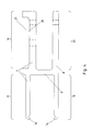
- connection between in each case two support profiles 4, 4 ', 5, 5', 6 ', 6' lying adjacent to each other in relation to the width extension of the bridge, ie viewed in cross section through the bridge comprise latching between the support profiles.
- one of the two supporting profiles to be connected (based on the unconnected state) freely projecting portions 11, 12 of the upper and lower bridge 7, 8 up.
- These freely projecting sections 11, 12 thus project beyond a connecting web 9 in the direction of the width of the bridge.
- latching recesses 15, 16 of the adjacent support section 4, 4 ', 5, 5', 6, 6 'snapped are in the connected state in latching recesses 15, 16 of the adjacent support section 4, 4 ', 5, 5', 6, 6 'snapped.
- the locking recesses 15, 16 thus form a locking seat for the latching connection.
- the sections 11, 12 are spread apart under elastic prestressing of the sections 11, 12, so that the distance between the latching lugs 13, 14 is increased.
- the sections 11, 12 are released and the locking lugs 13, 14 move into the locking recesses 15, 16 a.
- the connected state remains a spreading of the sections 11, 12 relative to the relaxed state, ie, the locking lugs 13, 14 have a greater distance than in the relaxed state, which is present before the spreading apart of the sections 11, 12 and the connection to the other support profile (and would also adjust again after the separation of the two support profiles).
- a mutually directed force is exerted by the sections 11, 12.
- the sections 11, 12 after the manufacture of the support profile in the relaxed state towards each other towards their free ends, for example, run towards each other, e.g. at an angle in the range between 1 ° to 3 °.
- the sections 11, 12 In connected to the adjacent support profile state, the sections 11, 12 preferably run parallel to each other.
- the clamping force applied by the latching connection counteracts a distortion of the two interconnected support profiles during welding. An additional clamping of the support profiles during welding can be omitted thereby.
- large-scale elements of the upper belt 1 or lower belt 2 can first be formed with the described connections of the support profiles, which are installed in the sequence.
- the sections 11, 12 could as latching elements instead of mutually facing latching noses 13, 14 also facing each other, upwardly and downwardly facing locking recesses, which cooperate with mutually away latching lugs, which form the latching seat.
- the mutually facing locking elements of the sections 11, 12 could also be formed by a latching lug and a latching recess and the latching elements of the latching seat directed away from each other would then correspondingly comprise a latching recess and a latching lug.
- a mutually directed bias for holding in the locking seat sections 11, 12 may also have an exploded bias.
- the sections 11, 12 would then be directed away from each other, pointing up and down locking elements (locking lugs or locking recesses).
- the sections 11, 12 would be compressed, so that the locking elements formed in the form of locking lugs or locking recesses approach each other.
- the distance between the locking elements of the sections 11, 12 would be less than in the relaxed state, which is present before the compression of the sections 11, 12 and the connection with the adjacent support profile, so that Locking elements of the sections 11, 12 are resiliently clamped against mutually directed locking elements on the other support profile.
- the sections 11, 12 After the preparation of the support profile and in the relaxed state, the sections 11, 12 in this case preferably run apart towards their free ends, eg in the angular range of 1 ° to 3 °. In connected to the adjacent support profile state, the sections 11, 12 preferably again in parallel.
- the locking seat is in a range of the width extension of the support profile 4, 4 ', 5', in which a connecting web 9 is located.
- a connecting web 9 is located.
- the edge profiles 5, 5 'of the upper belt 1 have in the direction of the respective side edge of the bridge projecting portions 19, 20 of the upper web 7 and lower web 8.
- the projecting portion 19 of the upper web 7 is provided with a seat 21 for fixing a part of a railing 23.
- This seat 21 is formed in the illustrated embodiment of a recess in the upper web 7.
- the bottom of this depression in this case has a gradation, wherein a recess 24 is formed in the bottom.
- 5 ' are at regular intervals set screws 25 which extend between the projecting portions 19, 20.
- the screws 25 are formed as screwed into threaded holes in the upper webs 7 threaded bolt on the below the lower web 8, a nut 26 is screwed.
- lock nuts 27, 28 are tightened.
- the foot plate 22 of the railing 23 is inserted.
- the foot plate 22 is in this case only in two-sided marginal areas of the seat 21 (based on the cross section) on the ground.
- the base plate 22 is clamped by clamping screws 29 with the upper web 7.
- connecting pieces 30 can, for example, of in
- the inclination of the portion 19 can be changed by bending the portion 19, whereby the adjustment of the vertical orientation of the railing 23 is made possible.
- the measured in the longitudinal direction of the bridge lengths of the support profiles 4, 4 ', 5, 5', 6, 6 ' are substantially larger than their widths, preferably at least five times larger, more preferably at least ten times larger.
- the ends of lying in cross-section adjacent support profiles 4, 4 ', 5, 5', 6, 6 'at different locations terminate, so that the shocks are offset by longitudinally adjacent support profiles. Due to the resulting overlaps of the end regions of juxtaposed longitudinally offset support profiles, the connections between the support profiles are facilitated.
- These joints preferably include welds in the overlap area. It can also be provided intermediate pieces which protrude into the hollow chambers of two longitudinally adjoining support profiles.
- the height of the support profiles 4, 4 ', 5, 5', 6, 6 ' is preferably in the range of 40mm to 120mm.
- the width of a hollow chamber 10 of such a hollow chamber 10 having supporting profile 4, 4 ', 5', 6, 6 ' may, for example, in the range of 50mm to 150mm.
- lateral cover profiles or cover plates 31, 32 may be provided which are connected to the upper flange 1 and the lower flange 2, for example by welding, screwing or snap connections.
- the edge support section 5 has projecting portions 11, 12 with locking elements and the edge profile 5 'has a locking seat.
- the two edge-support profiles 5, 5 'could also be formed the same (where they are used on the two sides of the bridge by 180 ° about a vertical axis pivoted against each other).
- both edge-support profiles cantilevered sections 11, 12 or both edge support profiles could have a snap fit.
- a coupling support profile may be provided, which has on its opposite sides in cross-section each a snap fit or each projecting portions 11, 12 with locking elements.
- An inventively modular bridge can advantageously be quickly and easily assembled from a few standard components.
Landscapes
- Engineering & Computer Science (AREA)
- Architecture (AREA)
- Civil Engineering (AREA)
- Structural Engineering (AREA)
- Bridges Or Land Bridges (AREA)
Applications Claiming Priority (1)
| Application Number | Priority Date | Filing Date | Title |
|---|---|---|---|
| DE201010029161 DE102010029161A1 (de) | 2010-05-20 | 2010-05-20 | Brücke |
Publications (1)
| Publication Number | Publication Date |
|---|---|
| EP2388376A2 true EP2388376A2 (fr) | 2011-11-23 |
Family
ID=44117095
Family Applications (1)
| Application Number | Title | Priority Date | Filing Date |
|---|---|---|---|
| EP11003549A Withdrawn EP2388376A2 (fr) | 2010-05-20 | 2011-05-02 | Pont |
Country Status (2)
| Country | Link |
|---|---|
| EP (1) | EP2388376A2 (fr) |
| DE (1) | DE102010029161A1 (fr) |
Cited By (1)
| Publication number | Priority date | Publication date | Assignee | Title |
|---|---|---|---|---|
| CN103722297A (zh) * | 2013-12-16 | 2014-04-16 | 中铁宝桥集团有限公司 | 钢箱梁空腹式横隔板组焊装备及制作工艺 |
Family Cites Families (3)
| Publication number | Priority date | Publication date | Assignee | Title |
|---|---|---|---|---|
| US4129917A (en) * | 1978-03-27 | 1978-12-19 | Eugene W. Sivachenko | Bridge structure |
| DE2928513A1 (de) * | 1979-07-14 | 1981-01-29 | Peter Dipl Ing Dr Techn Wagner | Flyover-bruecken-system |
| US7069614B1 (en) * | 1997-02-28 | 2006-07-04 | Manufacturers Equity Trust | Modular span multi-cell box girder bridge system |
-
2010
- 2010-05-20 DE DE201010029161 patent/DE102010029161A1/de not_active Withdrawn
-
2011
- 2011-05-02 EP EP11003549A patent/EP2388376A2/fr not_active Withdrawn
Non-Patent Citations (1)
| Title |
|---|
| None |
Cited By (1)
| Publication number | Priority date | Publication date | Assignee | Title |
|---|---|---|---|---|
| CN103722297A (zh) * | 2013-12-16 | 2014-04-16 | 中铁宝桥集团有限公司 | 钢箱梁空腹式横隔板组焊装备及制作工艺 |
Also Published As
| Publication number | Publication date |
|---|---|
| DE102010029161A1 (de) | 2011-11-24 |
Similar Documents
| Publication | Publication Date | Title |
|---|---|---|
| DE2854074C2 (fr) | ||
| AT390111B (de) | Schalung zur errichtung von baukoerpern aus gussfaehigen materialien, wie beispielsweise beton | |
| DE69406930T2 (de) | Leichte leitschranken für brücken | |
| EP2253764A2 (fr) | Treillis en forme de cadre | |
| EP2165030B1 (fr) | Système de mât | |
| WO2006086808A1 (fr) | Cadre-support pour modules de cellules ou de collecteurs solaires en forme de plaques | |
| EP1544377B1 (fr) | Element de coffrage pour murs courbes | |
| EP1905900A2 (fr) | Pont doté de deux plaques en treillis et son procédé de fabrication | |
| EP3552931B1 (fr) | Aide à la montée | |
| DE2540267A1 (de) | Aus scheiben zusammengesetztes tragwerk, insbesondere fuer eine zerlegbare bruecke | |
| EP2388376A2 (fr) | Pont | |
| AT500952B1 (de) | Gerüstträger aus aluminium | |
| DE202006012495U1 (de) | Tragprofil für eine Solarmodulreihe | |
| DE102009003087A1 (de) | Schwerlast-Verteilerplatte | |
| EP1679404A2 (fr) | Structure d'appui au joint de deux parties d'un pont transportable | |
| AT413115B (de) | Wandersteg zum anbringen an einer felswand | |
| DE102007055479B4 (de) | Knotenelement für eine Fachwerkskonstruktion | |
| DE60015053T2 (de) | Deck | |
| AT528501B1 (de) | Vorrichtung zur Montage von Solarpanels | |
| EP1288392B1 (fr) | Structure de support pour un système porteur d'une structure d'estrade, de podium, d'échafaudage ou similaire | |
| AT525980B1 (de) | Baugruppe bestehend aus einem Rohr und einer Verbindungsbaugruppe | |
| EP3427851A1 (fr) | Profilé de construction et combinaison de profilés comprenant au moins deux profilés de construction et un support de main courante | |
| DE3122860C2 (de) | Gliedergurt für Beton-Rundschalungen | |
| EP0165932B1 (fr) | Mecanisme de couplage pour relier des poutrelles profilees d'une maniere rigide a la flexion | |
| DE102006023404B4 (de) | Zeltboden |
Legal Events
| Date | Code | Title | Description |
|---|---|---|---|
| AK | Designated contracting states |
Kind code of ref document: A2 Designated state(s): AL AT BE BG CH CY CZ DE DK EE ES FI FR GB GR HR HU IE IS IT LI LT LU LV MC MK MT NL NO PL PT RO RS SE SI SK SM TR |
|
| AX | Request for extension of the european patent |
Extension state: BA ME |
|
| PUAI | Public reference made under article 153(3) epc to a published international application that has entered the european phase |
Free format text: ORIGINAL CODE: 0009012 |
|
| STAA | Information on the status of an ep patent application or granted ep patent |
Free format text: STATUS: THE APPLICATION IS DEEMED TO BE WITHDRAWN |
|
| 18D | Application deemed to be withdrawn |
Effective date: 20141202 |