EP2388536A2 - Pied de montage pour modules solaires et système de montage doté de plusieurs pieds de montage de ce type - Google Patents
Pied de montage pour modules solaires et système de montage doté de plusieurs pieds de montage de ce type Download PDFInfo
- Publication number
- EP2388536A2 EP2388536A2 EP11163149A EP11163149A EP2388536A2 EP 2388536 A2 EP2388536 A2 EP 2388536A2 EP 11163149 A EP11163149 A EP 11163149A EP 11163149 A EP11163149 A EP 11163149A EP 2388536 A2 EP2388536 A2 EP 2388536A2
- Authority
- EP
- European Patent Office
- Prior art keywords
- wind deflector
- mounting
- leg
- mounting system
- mounting foot
- Prior art date
- Legal status (The legal status is an assumption and is not a legal conclusion. Google has not performed a legal analysis and makes no representation as to the accuracy of the status listed.)
- Withdrawn
Links
- 239000004033 plastic Substances 0.000 claims abstract description 11
- 229920003023 plastic Polymers 0.000 claims abstract description 11
- 239000000463 material Substances 0.000 claims abstract description 5
- 230000007704 transition Effects 0.000 claims description 7
- 239000000758 substrate Substances 0.000 abstract description 6
- 239000012528 membrane Substances 0.000 abstract 1
- 238000009434 installation Methods 0.000 description 8
- 238000004519 manufacturing process Methods 0.000 description 3
- 229910000831 Steel Inorganic materials 0.000 description 2
- 230000001154 acute effect Effects 0.000 description 2
- 230000000694 effects Effects 0.000 description 2
- 229910052751 metal Inorganic materials 0.000 description 2
- 239000002184 metal Substances 0.000 description 2
- 239000010959 steel Substances 0.000 description 2
- 229920002430 Fibre-reinforced plastic Polymers 0.000 description 1
- 229910052782 aluminium Inorganic materials 0.000 description 1
- XAGFODPZIPBFFR-UHFFFAOYSA-N aluminium Chemical compound [Al] XAGFODPZIPBFFR-UHFFFAOYSA-N 0.000 description 1
- 238000004873 anchoring Methods 0.000 description 1
- 238000005452 bending Methods 0.000 description 1
- 230000015572 biosynthetic process Effects 0.000 description 1
- 238000006243 chemical reaction Methods 0.000 description 1
- 150000001875 compounds Chemical class 0.000 description 1
- 230000001419 dependent effect Effects 0.000 description 1
- 238000006073 displacement reaction Methods 0.000 description 1
- 230000007613 environmental effect Effects 0.000 description 1
- 239000011151 fibre-reinforced plastic Substances 0.000 description 1
- 238000003780 insertion Methods 0.000 description 1
- 230000037431 insertion Effects 0.000 description 1
- 238000004382 potting Methods 0.000 description 1
- 230000000630 rising effect Effects 0.000 description 1
Images


Classifications
-
- F—MECHANICAL ENGINEERING; LIGHTING; HEATING; WEAPONS; BLASTING
- F24—HEATING; RANGES; VENTILATING
- F24S—SOLAR HEAT COLLECTORS; SOLAR HEAT SYSTEMS
- F24S25/00—Arrangement of stationary mountings or supports for solar heat collector modules
- F24S25/60—Fixation means, e.g. fasteners, specially adapted for supporting solar heat collector modules
- F24S25/63—Fixation means, e.g. fasteners, specially adapted for supporting solar heat collector modules for fixing modules or their peripheral frames to supporting elements
- F24S25/634—Clamps; Clips
- F24S25/636—Clamps; Clips clamping by screw-threaded elements
-
- F—MECHANICAL ENGINEERING; LIGHTING; HEATING; WEAPONS; BLASTING
- F24—HEATING; RANGES; VENTILATING
- F24S—SOLAR HEAT COLLECTORS; SOLAR HEAT SYSTEMS
- F24S25/00—Arrangement of stationary mountings or supports for solar heat collector modules
- F24S25/10—Arrangement of stationary mountings or supports for solar heat collector modules extending in directions away from a supporting surface
- F24S25/11—Arrangement of stationary mountings or supports for solar heat collector modules extending in directions away from a supporting surface using shaped bodies, e.g. concrete elements, foamed elements or moulded box-like elements
-
- F—MECHANICAL ENGINEERING; LIGHTING; HEATING; WEAPONS; BLASTING
- F24—HEATING; RANGES; VENTILATING
- F24S—SOLAR HEAT COLLECTORS; SOLAR HEAT SYSTEMS
- F24S25/00—Arrangement of stationary mountings or supports for solar heat collector modules
- F24S25/10—Arrangement of stationary mountings or supports for solar heat collector modules extending in directions away from a supporting surface
- F24S25/16—Arrangement of interconnected standing structures; Standing structures having separate supporting portions for adjacent modules
-
- F—MECHANICAL ENGINEERING; LIGHTING; HEATING; WEAPONS; BLASTING
- F24—HEATING; RANGES; VENTILATING
- F24S—SOLAR HEAT COLLECTORS; SOLAR HEAT SYSTEMS
- F24S25/00—Arrangement of stationary mountings or supports for solar heat collector modules
- F24S25/60—Fixation means, e.g. fasteners, specially adapted for supporting solar heat collector modules
- F24S25/61—Fixation means, e.g. fasteners, specially adapted for supporting solar heat collector modules for fixing to the ground or to building structures
- F24S25/617—Elements driven into the ground, e.g. anchor-piles; Foundations for supporting elements; Connectors for connecting supporting structures to the ground or to flat horizontal surfaces
-
- F—MECHANICAL ENGINEERING; LIGHTING; HEATING; WEAPONS; BLASTING
- F24—HEATING; RANGES; VENTILATING
- F24S—SOLAR HEAT COLLECTORS; SOLAR HEAT SYSTEMS
- F24S25/00—Arrangement of stationary mountings or supports for solar heat collector modules
- F24S2025/80—Special profiles
-
- F—MECHANICAL ENGINEERING; LIGHTING; HEATING; WEAPONS; BLASTING
- F24—HEATING; RANGES; VENTILATING
- F24S—SOLAR HEAT COLLECTORS; SOLAR HEAT SYSTEMS
- F24S40/00—Safety or protection arrangements of solar heat collectors; Preventing malfunction of solar heat collectors
- F24S40/80—Accommodating differential expansion of solar collector elements
- F24S40/85—Arrangements for protecting solar collectors against adverse weather conditions
-
- Y—GENERAL TAGGING OF NEW TECHNOLOGICAL DEVELOPMENTS; GENERAL TAGGING OF CROSS-SECTIONAL TECHNOLOGIES SPANNING OVER SEVERAL SECTIONS OF THE IPC; TECHNICAL SUBJECTS COVERED BY FORMER USPC CROSS-REFERENCE ART COLLECTIONS [XRACs] AND DIGESTS
- Y02—TECHNOLOGIES OR APPLICATIONS FOR MITIGATION OR ADAPTATION AGAINST CLIMATE CHANGE
- Y02B—CLIMATE CHANGE MITIGATION TECHNOLOGIES RELATED TO BUILDINGS, e.g. HOUSING, HOUSE APPLIANCES OR RELATED END-USER APPLICATIONS
- Y02B10/00—Integration of renewable energy sources in buildings
- Y02B10/10—Photovoltaic [PV]
-
- Y—GENERAL TAGGING OF NEW TECHNOLOGICAL DEVELOPMENTS; GENERAL TAGGING OF CROSS-SECTIONAL TECHNOLOGIES SPANNING OVER SEVERAL SECTIONS OF THE IPC; TECHNICAL SUBJECTS COVERED BY FORMER USPC CROSS-REFERENCE ART COLLECTIONS [XRACs] AND DIGESTS
- Y02—TECHNOLOGIES OR APPLICATIONS FOR MITIGATION OR ADAPTATION AGAINST CLIMATE CHANGE
- Y02B—CLIMATE CHANGE MITIGATION TECHNOLOGIES RELATED TO BUILDINGS, e.g. HOUSING, HOUSE APPLIANCES OR RELATED END-USER APPLICATIONS
- Y02B10/00—Integration of renewable energy sources in buildings
- Y02B10/20—Solar thermal
-
- Y—GENERAL TAGGING OF NEW TECHNOLOGICAL DEVELOPMENTS; GENERAL TAGGING OF CROSS-SECTIONAL TECHNOLOGIES SPANNING OVER SEVERAL SECTIONS OF THE IPC; TECHNICAL SUBJECTS COVERED BY FORMER USPC CROSS-REFERENCE ART COLLECTIONS [XRACs] AND DIGESTS
- Y02—TECHNOLOGIES OR APPLICATIONS FOR MITIGATION OR ADAPTATION AGAINST CLIMATE CHANGE
- Y02E—REDUCTION OF GREENHOUSE GAS [GHG] EMISSIONS, RELATED TO ENERGY GENERATION, TRANSMISSION OR DISTRIBUTION
- Y02E10/00—Energy generation through renewable energy sources
- Y02E10/40—Solar thermal energy, e.g. solar towers
- Y02E10/47—Mountings or tracking
Definitions
- the invention relates to a mounting foot for solar modules and a mounting system, in particular a flat roof mounting system for solar modules, with such mounting feet.
- this mounting system is usually installed without direct attachment or connection to the building.
- the securing of the mounting system against shifting or lifting takes place via ballast, whereby, however, the maximum load of the flat roof is to be observed.
- the mounting system serving as a substructure thus forms a roof attachment to which the solar modules are fastened at a desired angle of inclination.
- the wind deflectors are usually screwed onto the substructure, flat plates, usually thin metal plates.
- numerous screws which can be stressed by tension are necessary for anchoring the wind deflectors. Accordingly, the installation of the wind deflector is very time consuming and therefore expensive.
- the object of the invention is to provide a simple and inexpensive producible mounting base and a mounting system for solar modules, which allows easy installation of wind deflectors (wind deflectors).
- a mounting foot for solar modules with a base body which has at least one footprint with which the mounting foot can be supported on a substrate, a leg projecting upwardly from the main body and an upper support for a first inclined module plate is preferably arranged at the free end of the leg, wherein the leg forms a receptacle for a wind deflector.
- the mounting foot preferably has a lower support connected to the main body for a non-coplanar to the first module plate, adjacent, second inclined module plate on.
- the receptacle for the ballast element in particular the entire leg with the receptacle, preferably extends obliquely upward from the lower support, whereby a desired distance between two adjacent rows of solar modules can be set.
- the receptacle is formed on the leg of the mounting foot guide groove for receiving a lateral edge of the wind deflector.
- the installation of the wind deflector by simply inserting into the guide groove.
- Abhebe law acting on the wind deflector can thus be generally or at least received in the lateral edge region by the guide, so that less, in particular no additional fastening means are necessary.
- the guide groove can be curved in Nutlteilsraum.
- a slight, preferably arcuate curvature of the guide a mounting of the wind deflector is possible under low bias, whereby a disturbing noise fines is prevented by rattling in the guide groove wind deflector.
- the requirements for a precision fit between the wind deflector and the longitudinal groove would have to be significantly increased in order to ensure a rattle-free wind deflector attachment.
- this would lead to increased effort and thus additional costs in the production of the mounting system.
- the wind deflector may have a deviating from a plane shape, which provides a tension in the guide groove.
- an inventive mounting system in particular a flat roof mounting system for solar modules, with several of the mounting feet described above and a wind deflector, which extends between two mounting feet and is mounted on both sides in the recordings of the mounting feet.
- the mounting system comprises at least one cross-connection strut for connecting two laterally adjacent mounting feet, the cross-connection strut forming a bearing for the lower edge of the wind deflector.
- the cross connection strut thus advantageously takes on two functions, namely, on the one hand, the connection of adjacent ones Mounting feet in the transverse direction contributes to the formation of a large, modular system unit, as well as the other storage of the wind deflector.
- the lower edge of the wind deflector engages in a longitudinal groove of the cross connection strut.
- the lower edge of the wind deflector can record by simply inserting into the longitudinal groove acting on the wind deflector Abhebe idea without additional fasteners such as screws or rivets are necessary.
- An upper edge of the wind deflector can be fixed at the free end of the leg by a fastening means, in particular a clamp.
- this clamp serves at the same time for fixing the solar modules against lifting, that is, it acts in a direction perpendicular to the module plate plane direction.
- the wind deflector is angled several times in cross-section, in particular in a stepped step shape.
- This angled design provides for a wind load for greater stability of the wind deflector against bulging.
- a reflection of the sunlight through the wind deflector to the opposite solar module row is possible with a suitable, oblique bending, resulting in a simple and advantageous manner to an increased energy yield.
- the angled surface is particularly light and / or shiny.
- the wind deflector is a ballast element and has a ballast material, preferably concrete on. Wind deflector and ballast element are thus combined in an advantageous combination element, which reduces the number of system components and thus simplifies the installation of the mounting system.
- the Figures 1 and 2 show a mounting base 10 for solar modules, with a base body 12, an integrally connected to the base 12 upper support 14 for a first inclined module plate 16 and integrally connected to the base 12 lower support 18 for a non-coplanar to the first module plate 16, adjacent , second inclined module plate 20.
- the base body 12 has at least one base 22, with which the mounting foot 10 on a substrate 24, such as a roof of a flat roof, can be supported.
- the upper support 14 in this case has a greater distance to a plane spanned by the base 22 level than the lower support 18th
- FIG. 2 a section of a solar system 25 shown with a mounting system 26 for solar modules, wherein the present mounting system 26 is a flat roof mounting system with a corresponding horizontal surface 24 and a plurality of mounting feet 10 according to FIG. 1 having.
- the mounting system 26 forms together with the module plates 16, 20 formed as solar modules the Solar system 25. Except on flat roofs, a use of the mounting system 26 is also conceivable on pitch roofs with low roof pitch or other ground 24 with low inclination.
- the mounting foot 10 In its primary function as a solar module carrier, the mounting foot 10 provides height-offset supports 14, 18 for up to four module plates 16, 20. Furthermore, the mounting foot 10 also performs a connection function between two rows of solar modules, so that the mounting system 26, which has a plurality of such mounting feet 10 can be connected to a modular unit with minimal effort and consequently no unwanted displacement of individual solar modules or individual rows of solar modules is possible.
- module plates 16, 20 As a solar module row while several adjacent module plates 16, 20 are designated, which are aligned largely coplanar, that is, lie substantially in a plane. In contrast, the module plates 16, 20 of different solar module rows are arranged non-coplanar and lie in different, albeit mostly parallel planes.
- the mounting feet 10 can be used universally and are not limited to specific module plate dimensions.
- the mounting system 26 comprises a plurality of inclined or tilted relative to a plane defined by the base surface 22 solar modules, which according to FIG. 2 are divided into two rows of solar modules with first module plates 16 and second module plates 20, wherein in FIG. 2 By way of example, only a second module plate 20 is shown.
- the inclination or inclination of the solar modules is usually oriented so that an upper side of the solar modules is facing south.
- a direction of inclination of the solar modules is defined as the longitudinal direction 28 of the mounting system 26, so that the longitudinal direction 28 in a completed solar system 25 according to FIG. 2 usually corresponds to the north-south direction.
- a solar module row extends in a transverse direction 30, which usually corresponds to the west-east direction.
- the free end of the leg 34 is formed with the lower support 18 as a fork bearing for receiving a (seen from the south) front edge 36 of the module plate 16, 20 (see also FIG. 2 ).
- the fork bearing is designed so that it allows a limited pivoting of the module plate 16, 20 to the lower support 18, so that the mounting base 10 can be used in the same design for different angles of inclination of the solar modules.
- both legs 32, 34 for the supports 14, 18 each have an acute angle ⁇ , ⁇ with the base 22, wherein the legs 32, 34 in the longitudinal direction 28 are directed away from each other.
- the leg 32 of the upper support 14 is directed away from the lower support 18 and includes an acute (Anstell-) angle ⁇ , that is an angle of 0 ° ⁇ ⁇ 90 ° with the base 22 a. Due to the dynamic pressure occurring in a wind load, the angle of attack ⁇ of the leg 32 is preferably between 50 ° and 80 °. Angle of attack ⁇ 90 ° are conceivable in principle, but for the above-mentioned reason, only in special exceptional cases makes sense.
- the leg 34 of the lower support 18 is usually so short that its angle of attack ⁇ has no appreciable influence on the mounting system 26. Therefore, the in FIG. 1 drawn angle ⁇ of the leg 34 also assume values of ⁇ ⁇ 90 °.
- the main body 12 of the mounting foot 10 comprises a first main body portion 37 with the leg 32, a second main body portion 38 with the leg 34 and a connecting web 39 between the main body portions 37, 38, wherein the base surface 22 is interrupted in the region of the connecting web 39.
- one single, large footprint 22 provides this embodiment at locally very uneven ground 24 the advantage of greater stability due to less tendency to tilt.
- interrupted floor space 22 allows a laying of cables and cables in the transverse direction 30 directly on the ground 24, below the connecting web 39. By the risk of damage to the cables or cables is minimized.
- the laying of the cables and cables in the transverse direction 30 in a (not shown) cable channel which is secured by means of a cable channel holder 40 at the free end of the leg 32 (see. FIGS. 6 and 7 ).
- the cables and cables are in this case after completion of the solar system 25 protected under the solar modules.
- FIG. 1 are on the leg 32 of the upper support 14 bearing portions 41, 42, 43 for a wind deflector 44 and a ballast element 46 (see also FIG. 2 to see).
- the bearing portion 41 for the wind deflector 44 is a guide groove 64 which extends in the longitudinal direction of the leg 32 and can receive lateral ends of the wind deflector 44.
- An angle of attack of the wind deflector 44 thus corresponds to the angle of attack ⁇ of the leg 32 with the upper support 14.
- the bearing portions 42, 43 for the ballast element 46 are as a support surface in the transition region between the base body 12 and the leg 32 or laterally protruding bearing tongue on the leg 32nd educated.
- the bearing portions 42, 43 are arranged so that an angle of attack of the plate-shaped ballast elements 46 substantially corresponds to the angle ⁇ of the leg 32 with the upper support 14.
- the mounting system 26 points in FIG. 2 , as already explained, several in the longitudinal direction 28 successively arranged mounting feet 10 to the front edge 36 of a module plate 16, 20 on the lower support 18 of a front mounting foot 10 and a rear edge 48 of this module plate 16, 20 to store the upper support 14 of a rear mounting base 10.
- the mounting system 26 comprises longitudinal connecting struts 50 for connecting two mounting feet 10 adjacent in the longitudinal direction 28 and cross connecting struts 52 for connecting two mounting feet 10 adjacent in the transverse direction 30 FIG. 3 refer to, in which a section of the mounting system 26 is shown.
- the longitudinal connecting struts 50 are preferably made of steel, but may alternatively be plastic or Alustreben.
- the cross-connecting struts 52 are preferably metal struts, in particular when they serve as supports for the ballast elements 46. Alternatively, of course, but also cross connection struts 52 made of plastic are conceivable.
- the wind deflector 44 covers the entire area between two mounting feet 10, so that the area under the module plates 16, 20 is almost completely encapsulated.
- the wind deflector 44 covers only a part of about 50-90% of the area and thus allows an exchange of air between the top and bottom. As a result, the wind load of the mounting system 26 can be reduced.
- the cross connection struts 52 are preferably channel-shaped and each extend between two adjacent mounting feet 10, wherein the ends of each cross connecting strut 52 are fixed to the mounting feet 10. According to FIG. 3 the ends of the cross connecting strut 52 are inserted into recesses of the legs 32 and lie on the likewise groove-shaped bearing portion 42 in the transition region between the base body 12 and leg 32 (see also FIG. 6 ).
- the individual mounting feet 10 according to FIG. 1 each have offset supports 14, 18 for up to four module plates 16, 20, wherein in the corner and edge regions of the mounting system 26 only one or two supports 14, 18 are used.
- correspondingly adapted mounting feet 10 ' are used, which consist essentially only of the second body portion 38 with the lower supports 18 (see. FIG. 2 ).
- the bearing portion 42 for receiving a cross-connecting strut 52 exceptionally in the transition region between the base body 12 and the legs 34 of the lower support 18 is formed.
- adapted mounting feet 10 can be used, which consist essentially only of the first base portion 37 with the upper supports 14 (see. FIG. 6 ).
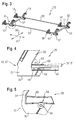
- FIG. 4 shows a detailed view A of the mounting system 26 in a connection region between the mounting foot 10 and longitudinal connecting strut 50, said connecting region for orientation in FIG. 3 circled dashed.
- the base body 12 of the mounting foot 10 at its longitudinally opposite ends 28 each have a fastening portion 53 for a longitudinal connecting strut 50.
- a fastening means 54 is provided between the longitudinal connecting strut 50 and the base body 12, which allows locking of mounting foot 10 and longitudinal connecting strut 50 in the longitudinal direction 28 at different positions.
- the fastening means 54 in the present case comprises a screw which cooperates with a slot 56 in the longitudinal connecting strut 50 in order to allow a variable in the longitudinal direction 28 locking.
- FIG. 5 shows the detail view according to FIG. 4 However, without the longitudinal connecting strut 50.
- the attachment portion 53 of the main body 12 can be seen in detail and good to see that the fastening means 54 locking geometries 58 on the mounting base 10 has.
- These latching geometries 58 preferably interact with suitable latching geometries (not shown) on the longitudinal connecting strut 50, so that over the longitudinally displaceable connection between the mounting foot 10 and the longitudinal connecting strut 50 numerous different latching engagements are created.
- These locking engagements provide a locking in the longitudinal direction 28 without screwing, so that Align the mounting system 26 with little effort.
- a stop 60 is provided between the mounting foot 10 and the longitudinal connecting strut 50, the stop 60 delimiting an angular adjustment range around a central position in which the longitudinal connecting strut 50 runs parallel to the standing surface 22.
- This stop 60 is formed in the present embodiment on the mounting base 10 (see. FIG. 5 ) and has a Winkelverstell Highway in the order of about ⁇ 3 ° around the central position (see also FIG. 4 ). By this Winkelverstell Berlin unevenness and, for example, drainage reasons existing slope changes of the substrate 24 can be compensated.
- the mounting system 26 Since the mounting system 26 is subject to large temperature fluctuations and usually reaches dimensions of several meters both in the longitudinal direction 28 and in the transverse direction 30, the strains caused by temperature change are considerable. Thus, these thermal expansions do not lead to undesirably large voltages within the mounting system 26, for example, in the longitudinal direction 28 and / or in the transverse direction 30 rather centrally arranged mounting feet 10 in a plane spanned by its base surfaces 22 as a fixed bearing and the other mounting feet 10 in this plane as a plain bearing be educated.
- preferably sliding shoes 61 as in the FIGS. 1 and 6 indicated, provided so that the mounting feet 10 are supported on their base 22, optional sliding inserts and the shoes 61 on the ground 24.
- the mounting foot 10 is preferably made in one piece from aluminum, in particular as a die-cast. Alternatively, it can also be made of plastic, in particular fiber-reinforced plastic, or steel. From plastics it is also possible to produce relatively complex geometric shapes such as the mounting foot 10 with relatively little effort. Furthermore, for the mounting base 10 suitable plastics with sufficient strength, Durability and weather resistance comparatively inexpensive available, so that the mounting foot 10 can be produced very cost overall. Alternatively, of course, a multi-part production of the mounting base 10 is conceivable.
- FIG. 6 shows the mounting foot 10 ", which has no lower support 18 and thus at the rear, that is usually northern end of the mounting system 26 is used.
- the mounting base 10 “comprises the base body 12, which has a base 22, with which the mounting foot 10" can support the substrate 24, the base 12 upwardly projecting leg 32 and the upper support 14 for a first inclined module plate 16, which on free end of the leg 32 is arranged, wherein the leg 32 has a receptacle 62 for the wind deflector 44.
- the receptacle 62 forms a guide for the wind deflector 44 and is according to FIG. 6 Specifically, an integrally formed on the leg 32 guide groove 64 for receiving a lateral edge 66 of the Wendschotts 44th
- the FIG. 7 shows a section of the solar system 25 with installed wind deflector 44 and mounted solar module.
- the mounting system 26 comprises several mounting feet 10 and the wind deflector 44, which extends between two mounting feet 10 and is mounted on both sides with its lateral edges 66 in the receptacles 62 of the mounting feet 10.
- the wind deflector 44 thus extends in the assembled state from a lower edge 68 in the transition region between the leg 32 and the base body 12 to an upper edge 70 in the region of the free leg end and engages with its lateral edges 66 in the guide grooves 64 of the adjacent legs 32nd one.
- the guide groove 64 may be slightly curved in the groove longitudinal direction, so that upon insertion of the groove in the longitudinal direction preferably straight, flexible and elastic Wndschotts 44, a bias between Wendschott 44 and guide groove 64 is formed. By this bias disturbing rattling noise between the wind deflector 44 and guide 64 are prevented.
- the same effect can alternatively also be achieved with a guide groove 64 which is straight in the groove longitudinal direction and a wind deflector 44 curved in the groove longitudinal direction.
- the receptacle 62 has in accordance with FIGS. 1 and 6 at the lower end of the guide groove 64 a wind deflector stop 75 in the transition region between the leg 32 and the base body 12.
- a desired ground clearance of the mounting system 26, for example, for easy installation of a cable channel in the longitudinal direction 28, can be easily adjusted by this stop 75 and already considered in the manufacture of the mounting base 10.
- cross connection strut 52 can be seen for connecting two transversely adjacent mounting feet 10, wherein the cross connection strut 52 forms a line bearing for the lower edge 68 of the wind deflector 44.
- the cross connection strut 52 has a longitudinal groove 72 (FIG. FIG. 6 ), wherein the lower edge 68 of the installed wind deflector 44 (FIG. FIG. 7 ) engages in this longitudinal groove 72 of the cross-connecting strut 52, so that the wind deflector 44 is held at its lower edge 68 in a direction transverse to its plane of extent.
- a plane of extension of the wind deflector 44 while a plane is referred to, which is spanned by the cross-connecting strut 52 and the guide groove 64 in the leg 32. This also applies to the case that the wind deflector 44 is angled several times in cross-section.
- FIG. 8 shows a sectional detail of the solar system 25 in the region of the upper support 14.
- the wind deflector 44 is in this case angled several times in cross-section, in particular staircase-shaped.
- the wind deflector 44 is angled obliquely, so that the sunlight is reflected at a given position of the sun through the wind deflector 44 to the surface of the opposite solar module. This leads to an increased energy yield of the solar module, which makes this effect especially in well-reflective wind deflector surfaces, that is, for example, bright or shiny surfaces, positively noticeable.
- the wind deflector 44 is at least partially made of plastic.
- Plastics generally have sufficient flexibility and elasticity to form a certain bias in the guide groove 64, which prevents unwanted rattling noises of the wind deflector 44 in the guide groove 64.
- the occurring loads can be easily absorbed by a plastic wind deflector 44, since the Side edges 66 reliably in guide grooves 64 of the mounting feet 10 and the lower edge 68 is reliably held in the longitudinal groove 72 of the cross-connecting strut 52.
- still terminals 74 are provided which fix continuously or selectively the upper edge 70 of the wind deflector 44.
- the leg 32 additionally forms a bearing 76 for the plate-shaped ballast element 46, which in FIG. 8 is shown installed.
- the bulging of the wind deflector 44 is not a problem in wind load even in the case of a very thin trained bulkhead, since the wind deflector 44 can support the ballast element 46, such as a rigid concrete slab, with little deflection.
- the wind deflector 44 is plate-shaped, although in detail it may have a flat, slightly curved or stepped cross-section.
- the wind deflector 44 itself may be designed as a ballast element 46 and have a ballast material such as concrete.
- a ballast material such as concrete.
- simple concrete slabs can be used, which take over both the function of the wind deflector 44 and the function of the ballast element 46.
- plastic wind bulkheads manufactured as a hollow body structure can also be envisaged, the voids of which are filled as required with ballast material, for example concrete or another suitable potting compound.
- terminals 74 are applied to the free end of the leg 32, which both the upper and rear edge 48 of the module plates 16, 20 and the upper edge 70 of the wind deflector 44 fix.
- These terminals 74 are according to FIG. 8 anchored at the free end of the leg 32 in the mounting base 10, for example by means of a screw 78th
Landscapes
- Engineering & Computer Science (AREA)
- Physics & Mathematics (AREA)
- Life Sciences & Earth Sciences (AREA)
- Sustainable Development (AREA)
- Sustainable Energy (AREA)
- Thermal Sciences (AREA)
- Chemical & Material Sciences (AREA)
- Combustion & Propulsion (AREA)
- Mechanical Engineering (AREA)
- General Engineering & Computer Science (AREA)
- Photovoltaic Devices (AREA)
Applications Claiming Priority (1)
| Application Number | Priority Date | Filing Date | Title |
|---|---|---|---|
| DE102010029004A DE102010029004A1 (de) | 2010-05-17 | 2010-05-17 | Montagefuss für Solarmodule sowie Montagesystem mit mehreren solcher Montagefüsse |
Publications (1)
| Publication Number | Publication Date |
|---|---|
| EP2388536A2 true EP2388536A2 (fr) | 2011-11-23 |
Family
ID=44117540
Family Applications (1)
| Application Number | Title | Priority Date | Filing Date |
|---|---|---|---|
| EP11163149A Withdrawn EP2388536A2 (fr) | 2010-05-17 | 2011-04-20 | Pied de montage pour modules solaires et système de montage doté de plusieurs pieds de montage de ce type |
Country Status (2)
| Country | Link |
|---|---|
| EP (1) | EP2388536A2 (fr) |
| DE (1) | DE102010029004A1 (fr) |
Families Citing this family (1)
| Publication number | Priority date | Publication date | Assignee | Title |
|---|---|---|---|---|
| US10547270B2 (en) | 2016-02-12 | 2020-01-28 | Solarcity Corporation | Building integrated photovoltaic roofing assemblies and associated systems and methods |
-
2010
- 2010-05-17 DE DE102010029004A patent/DE102010029004A1/de not_active Withdrawn
-
2011
- 2011-04-20 EP EP11163149A patent/EP2388536A2/fr not_active Withdrawn
Non-Patent Citations (1)
| Title |
|---|
| None |
Also Published As
| Publication number | Publication date |
|---|---|
| DE102010029004A1 (de) | 2011-11-17 |
Similar Documents
| Publication | Publication Date | Title |
|---|---|---|
| EP2388539A2 (fr) | Socle de montage pour modules solaires et système de montage doté de plusieurs socles de montage de ce type | |
| DE102009051766B3 (de) | Photovoltaikanlage mit Reflektorelementen | |
| EP3683960B1 (fr) | Installation photovoltaïque | |
| DE10132557C2 (de) | Montageprofil zur Befestigung von Photovoltaik-Modulen und Montagesystem | |
| DE102008037964A1 (de) | Montagevorrichtung für Solarmodule mit einem großen Aspektverhältnis | |
| DE202008017946U1 (de) | Modul zur Umwandlung von Solarenergie in Elektrizität | |
| EP2307821A2 (fr) | Profilé de retenue et profilé d'étanchéité pour module en forme de plaque | |
| WO2010054795A1 (fr) | Support pour monter un panneau solaire | |
| DE202010006377U1 (de) | Unterkonstruktion für Solaranlage | |
| WO2010130461A1 (fr) | Dispositif de maintien et de fixation | |
| DE102009054242A1 (de) | Vorrichtung zur Befestigung mindestens eines Solarmoduls | |
| WO2012041827A1 (fr) | Système de montage pour fixer des installations photovoltaïques sur des toits en particulier plats | |
| DE202010004714U1 (de) | Photovoltaische Anlage aus Dünnschichtsolarmodulen | |
| DE102011007521A1 (de) | Unterkonstruktion für eine Solarmodul-Freilandanordnung | |
| DE102009055948A1 (de) | Profilelement eines Daches und Anordnung von Profilelementen | |
| DE202010001518U1 (de) | Vorrichtung zur Aufnahme eines Solarmoduls, insbesondere Photovoltaikmodul | |
| DE202013103076U1 (de) | Plattenmodulanordnung | |
| EP2400238A2 (fr) | Elévation d'un module solaire | |
| DE102008027301A1 (de) | Solaranlage | |
| EP2388537A2 (fr) | Pied de montage pour modules solaires et système de montage doté de plusieurs pieds de montage de ce type | |
| DE102018217108A1 (de) | Dachkonstruktion für carports mit pv-modulen sowie ein verfahren zum montieren eines derartigen carports | |
| EP2388536A2 (fr) | Pied de montage pour modules solaires et système de montage doté de plusieurs pieds de montage de ce type | |
| DE102008018077A1 (de) | Solarelement für Solaranlagen | |
| EP2416084A2 (fr) | Système de stockage pour modules solaires et installation solaire | |
| DE202011052032U1 (de) | Stützelement für ein Solarmodul |
Legal Events
| Date | Code | Title | Description |
|---|---|---|---|
| AK | Designated contracting states |
Kind code of ref document: A2 Designated state(s): AL AT BE BG CH CY CZ DE DK EE ES FI FR GB GR HR HU IE IS IT LI LT LU LV MC MK MT NL NO PL PT RO RS SE SI SK SM TR |
|
| AX | Request for extension of the european patent |
Extension state: BA ME |
|
| PUAI | Public reference made under article 153(3) epc to a published international application that has entered the european phase |
Free format text: ORIGINAL CODE: 0009012 |
|
| STAA | Information on the status of an ep patent application or granted ep patent |
Free format text: STATUS: THE APPLICATION IS DEEMED TO BE WITHDRAWN |
|
| 18D | Application deemed to be withdrawn |
Effective date: 20141101 |