EP2390417A2 - Endplatte für eine Einbaubohle eines Straßenfertigers - Google Patents
Endplatte für eine Einbaubohle eines Straßenfertigers Download PDFInfo
- Publication number
- EP2390417A2 EP2390417A2 EP11004083A EP11004083A EP2390417A2 EP 2390417 A2 EP2390417 A2 EP 2390417A2 EP 11004083 A EP11004083 A EP 11004083A EP 11004083 A EP11004083 A EP 11004083A EP 2390417 A2 EP2390417 A2 EP 2390417A2
- Authority
- EP
- European Patent Office
- Prior art keywords
- vertical section
- end plate
- screed unit
- guiding means
- respect
- Prior art date
- Legal status (The legal status is an assumption and is not a legal conclusion. Google has not performed a legal analysis and makes no representation as to the accuracy of the status listed.)
- Withdrawn
Links
- 239000000463 material Substances 0.000 claims abstract description 47
- 230000009471 action Effects 0.000 claims abstract description 16
- 230000008878 coupling Effects 0.000 claims description 39
- 238000010168 coupling process Methods 0.000 claims description 39
- 238000005859 coupling reaction Methods 0.000 claims description 39
- 238000006243 chemical reaction Methods 0.000 claims description 7
- 238000010438 heat treatment Methods 0.000 claims description 3
- 238000006073 displacement reaction Methods 0.000 claims 1
- 210000003477 cochlea Anatomy 0.000 description 6
- 230000008901 benefit Effects 0.000 description 4
- 230000000694 effects Effects 0.000 description 4
- 238000012986 modification Methods 0.000 description 4
- 230000004048 modification Effects 0.000 description 4
- 230000004075 alteration Effects 0.000 description 2
- 238000010420 art technique Methods 0.000 description 2
- 230000015556 catabolic process Effects 0.000 description 2
- 238000012423 maintenance Methods 0.000 description 2
- 239000002184 metal Substances 0.000 description 2
- 230000008859 change Effects 0.000 description 1
- 239000011796 hollow space material Substances 0.000 description 1
- 230000008595 infiltration Effects 0.000 description 1
- 238000001764 infiltration Methods 0.000 description 1
- 230000009467 reduction Effects 0.000 description 1
- 238000007493 shaping process Methods 0.000 description 1
- 238000010977 unit operation Methods 0.000 description 1
Images


Classifications
-
- E—FIXED CONSTRUCTIONS
- E01—CONSTRUCTION OF ROADS, RAILWAYS, OR BRIDGES
- E01C—CONSTRUCTION OF, OR SURFACES FOR, ROADS, SPORTS GROUNDS, OR THE LIKE; MACHINES OR AUXILIARY TOOLS FOR CONSTRUCTION OR REPAIR
- E01C19/00—Machines, tools or auxiliary devices for preparing or distributing paving materials, for working the placed materials, or for forming, consolidating, or finishing the paving
- E01C19/22—Machines, tools or auxiliary devices for preparing or distributing paving materials, for working the placed materials, or for forming, consolidating, or finishing the paving for consolidating or finishing laid-down unset materials
- E01C19/30—Tamping or vibrating apparatus other than rollers ; Devices for ramming individual paving elements
- E01C19/34—Power-driven rammers or tampers, e.g. air-hammer impacted shoes for ramming stone-sett paving; Hand-actuated ramming or tamping machines, e.g. tampers with manually hoisted dropping weight
- E01C19/40—Power-driven rammers or tampers, e.g. air-hammer impacted shoes for ramming stone-sett paving; Hand-actuated ramming or tamping machines, e.g. tampers with manually hoisted dropping weight adapted to impart a smooth finish to the paving, e.g. tamping or vibrating finishers
- E01C19/405—Power-driven rammers or tampers, e.g. air-hammer impacted shoes for ramming stone-sett paving; Hand-actuated ramming or tamping machines, e.g. tampers with manually hoisted dropping weight adapted to impart a smooth finish to the paving, e.g. tamping or vibrating finishers with spreading-out, levelling or smoothing means other than the tamping or vibrating means for compacting or smoothing, e.g. with screws for spreading-out the previously dumped material, with non-vibratory lengthwise reciprocated smoothing beam
Definitions
- the present invention relates to an end plate for a screed unit of a paver finisher according to the characteristics of the pre-characterizing part of claim 1.
- the present invention also relates to a screed unit of a paver finisher according to the characteristics of the pre-characterizing part of claim 29.
- the present invention also relates to a paver finisher according to the characteristics of the pre-characterizing part of claim 30.
- side refers to a position on the machine placed sideways with respect to the advancing direction of the same machine in working condition, according to the advancing direction of the machine indicated in the figures.
- the terms “right” and “left” are defined with respect to the advancing direction of the machine indicated in the figures.
- paver finisher machines also known in lingo as finishers, pavers, etc. are known. These machines consist of two main units:
- the screed unit When a screed width greater than the base unit width is required, some extensions are applied at the end of the same unit until the required width is reached. Said extensions are generally available with different widths and they can be applied in more sectors until the limit established by the unit maker is reached.
- the screed unit includes a central section having fixed length, connected by means of two towing arms to the tractor towing points.
- the central section generally consists of two sub-sections hinged to one another at the centre to obtain different screed transverse sections.
- an extensible screed unit it comprises a right side section and a left side section.
- the right side section and the left side section each have a width equal to about the half of the central section and are generally hydraulically extensible to obtain variable screed widths.
- the adjustment in height of the movable part is carried out according to the screed thickness and must be such as to allow a good contact with the support surface, with sufficient freedom of vertical movement to compensate possible unevenness of the same support surface.
- the base of the movable part of the end plate is generally provided with a slide to limit the pressure on the surface and avoid the end plate from being restrained during its push on the support surface, namely on the ground. If the end plate works correctly, the layer of screed material applied by the paver finisher presents vertical edges and a good local pre-compacting, that are important characteristics to carry out in accordance with the best workmanship the possible longitudinal coupling between the material in progress of screed and the material screed sideways in a step that precedes or follows the screed step in progress.
- auxiliary devices are utilized to increase the pressure on the ground of the movable part of the end plate, as springs or hydraulic cylinders. Such devices are interposed between the fixed part and the movable part of the end plate.
- the fixed part constitutes the reaction element to the vertical force exerted downwardly by the auxiliary device, which, therefore, exerts a pushing force downward to the movable part with respect to the fixed part of the end plate.
- the force that is applied depends on the spring deformation and is therefore variable according to the deformation undergone by the spring not only in its pre-loading step, but also following the deformation undergone by the spring because of the unevenness of the support surface and possible infiltration of material under the slide.
- the aim of this invention is to supply a screed unit for paver finisher that allows to obtain a most effective action of the movable part of the end plate.
- the solution in accordance with the present invention by the considerable creative contribution whose effect constitutes an immediate and not-negligible technical progress, presents various advantages.
- First of all the solution according to the present invention allows to avoid the resort to additional auxiliary devices to increase the pressure exerted on the support surface by the movable part of the end plate, at the same time ensuring an effective downward pushing action of the movable part of the same end plate.
- This besides benefits from the economical point of view also involves a greater reliability of the machine in its whole inasmuch there are less additional elements that could be subjected to breakdowns.
- the solution according to the present invention also allows a fast and prompt adjusting of the reciprocal position in height of the movable part of the end plate with respect to the fixed part of the end plate, according to the desired configuration of the machine and to the screed operating conditions.
- the solution according to the present invention moreover, also allows a fast release of the movable part of the end plate, for example in the case in which carrying out a maintenance intervention is necessary.
- the solution according to the present invention is also applicable to the existing machines, requiring less modifications to the same ones.
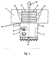
- the Fig. 1 shows schematically a wheeled tractor (13) and includes:
- the screed unit (17) is furthermore generally equipped with accessories of known art, as reciprocate motion blades, called tampers (not shown), with vertical action to facilitate the inserting of the material below the bottom plate (33), and vibrators (not shown) to confer a good screed finishing, as well as a heating system (not shown) to avoid the adhering of the material to the bottom plate (33) and to the tamper in the case of screed of hot bituminous conglomerate.
- tampers reciprocate motion blades
- vibrators not shown
- a heating system not shown
- the end plates (12) are used to retain the material delivered by the cochleas (4) in front of the screed unit (17) and to convey the material toward the longitudinal axis of the machine when the screed width tightens in case of the screed unit (17) with extensible sectors.
- some extension sectors (18) are applied at the ends of the same unit until the required width is reached.
- Such extension sectors (18) are generally available with different widths and more extension sectors (18) can be applied one after the other until the limit established by the maker of the screed unit (17) is reached.
- the retaining end plates (12) are applied sideways of the screed unit (17).
- the end plates (12) will be directly applied in correspondence of the respective ends of the central section (8), namely in correspondence of the right end and of the left end of the screed unit (17) in its whole.
- an end plate (12) will be applied in correspondence of the right end of the screed unit (17), namely in correspondence of the end of the right side section (10) and another end plate (12) will be applied in correspondence of the end of the left side section of the screed unit (17), namely in correspondence of the end of the left side section (11).
- extension sectors (18) are used at the ends of the screed unit (17) to increase the screed width of the main unit (19)
- an end plate (12) will be applied in correspondence of the right end of the last of the extension sectors (18) mounted in correspondence of the right side section (10) of the screed unit (17) and another end plate (12) will be applied in correspondence of the left end of the last of the extension sectors (18) mounted in correspondence of the left side section (11).
- the retaining end plates (12) of the material delivered by the cochlea (4) are generally fixed to the screed unit (17) by means of fastening bolts, but other equivalent fastening means can be used without exiting from the domain of the present invention.
- the end plates (12) applied on the right side and on the left side of the paver finisher (45) are symmetrical with respect to the advancing direction (46) of the machine. Therefore the description of the present invention will be limited to the specific case of an end plate (12) mounted on the left side of the screed unit (17), resulting obvious the application of the solution to the case of an end plate (12) mounted on the right side of the screed unit (17).
- the description related to the operation of the end plate (12) according to the present invention applies to both sides of the screed unit (17).
- the end plate (12) according to the present invention is described relating to the mounting on the left side of the screed unit.
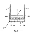
- the end plate (12) according to the present invention ( Fig. 7 ) consists of a frame (39) and of a vertical section (20).
- the frame (39) acts as support of the vertical section (20) according to what will be described in the following of the present description.
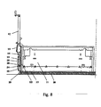
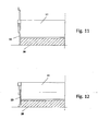
- the frame (39) is fixed ( Figs. 8 , 10 ) to the screed unit (17) of the paver finisher (45). It will be obvious that:
- each of the arms (21, 22) at least one guiding roll (23, 24) is mounted and if necessary at least one adjusting roll (25, 26) can be mounted.
- at least one guiding roll (23, 24) for each arm (21, 22), for example two guiding rolls (23, 24) for each arm is possible.
- providing even more adjusting rolls (25, 26) for each arm (21, 22), for example two adjusting rolls (25, 26) for each arm is possible.
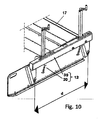
- the frontal guiding roll (23) and the rear guiding roll (24) are spaced ( Fig. 10 ) for a distance (d).
- the frame (39) can further comprise a fixed section (40) of the end plate (12) placed in correspondence of the backing zone with the screed unit (17), or with the backing zone of the extension sector (18) or with the backing zone with the corresponding side section (10, 11) of the screed unit (17).
- the fixed section (40) will be placed in correspondence of the side-wall (53) of the screed unit (17).
- the vertical section (20) will be sliding in the hollow space made up with fixed section (40) and side- wall (53) of the screed unit (17).
- the vertical section (20) of the end plate (12) is shaped ( figs.
- the frontal guide (27) and the rear guide (28) are inclined with respect to the direction orthogonal to the advancing direction (46) of the machine.
- the frontal guide (27) and the rear guide (28) are reciprocally parallel and are inclined according to an angle (b) greater than ninety-degree with respect to the advancing direction (46) of the machine and are placed at a reciprocal distance (d) equal to the distance (d) between the frontal guiding roll (23) and the rear guiding roll (24) previously described.
- the vertical section (20) of the end plate (12) further includes two coupling means (47) whose function will be described in the following of the present description. Therefore the end plate (12) according to the present invention ( Fig. 7 ) consists of a frame (39) and of a vertical section (20) that are different elements reciprocally coupled so that the vertical section (20) is free to move vertically with respect to the frame (39).
- the vertical section (20) is coupled to the frame (39) by means of a first coupling device (43) and a second coupling device (44).
- the first coupling device (43) is hooked on one side to one of the two fastening means (47) of the vertical section (20) and on the other side to the first lifting device (41 ) present on the frame (39).
- the second coupling device (44) is hooked from side to side of the two fastening means (47) of the vertical section (20) and on the other side to the second lifting device (42) present on the frame (39).
- the frame (39) includes lifting devices (41, 42) of the vertical section (20), and the lifting devices (41, 42) include coupling means (48) intended to the coupling of the vertical section (20).
- the vertical section (20) is thus liftable with respect to the ground and with respect to the frame (39) by means of lifting devices (41, 42).
- the coupling devices (43, 44) are represented as chains, but it will be evident that other equivalent forms of execution are possible, e.g. generic cables, metallic cables, etc.
- the coupling devices will be generic flexible coupling devices, to ensure that the end plate (12) can be lowered until the contact with the ground and successively further release the coupling devices to allow the necessary clearance in the vertical movement of the end plate (12) so that it can adapt to non-homogeneity of the ground on which it slides.
- the lifting devices (41, 42) include the previously described hook (48)
- the coupling of the coupling devices (43, 44) can be simply carried out by inserting a slot of these same or a chain ring that makes them up within the hook (48).
- the hook (48) can also comprise closure means able to prevent that the end of the coupling devices (43, 44) exits from the hook (48) once it has been inserted in the same hook (48).
- fastening means (47) of the vertical section (20) can be made in equivalent different ways within the aim of the present invention, for example by being themselves a hook secured to the vertical section (20) or a slot, a hole or a couple of holes within which a hook present in correspondence of the corresponding end of the coupling devices (43, 44) is secured.
- the frontal guiding roll (23) is in condition of support at the frontal guide (27) and the rear guiding roll (24) is in condition of support at the rear guide (28) and the vertical section (20) is suspended on the frame (39), by the connection of the first coupling device (43) with the corresponding first lifting device (41) and by the connection of the second coupling device (44) with the corresponding second lifting device (42).
- the end plate (12) thus consists of the frame (39) fixed to the screed unit (19) and of the vertical section that is suspended on the frame (39) by means of coupling devices (43, 44) and whose height with respect to the support surface, namely with respect to the ground, to can be adjusted by acting on the lifting devices (41, 42).
- the lifting of the end plate (12) by means of lifting devices (41, 42) favours the machine transportation.
- the whole ensemble of the end plate (12) can be engaged with the screed unit (19) by means of a hinging connection, that allows to rotate rearwards the whole group to bring again the machine width within the limits allowed for its haulage.
- the vertical section (20) is not supported by the coupling devices (43, 44), but is let free to follow the ground profile, helped in the contact by the particular inclination of the guides (27, 28) in condition of support to the guiding rolls (23, 24).
- the sliding of the slide placed at the bottom of the end plate on the surface causes reaction forces.
- the reaction forces tend to prevent the vertical movement of the movable part or vertical section (20) of the end plate (12) because of the increase of the friction on the vertical guides and because of the increase of the friction between the vertical section (20) and the fixed part or frame (39) of the end plates (12).
- the vertical section (20) is manually lowered by means of lifting devices (41, 42) that support the vertical section (20) by means of coupling devices (43, 44).
- the acting on the handwheels (49) causes the lowering of the hooks (48) to which the chains (43, 44) are fastened.
- the lowering of the vertical section (20) continues till when occurs the contact of the slide (29) with the support surface or ground.
- the vertical section (20) is still at least partially supported by the coupling devices (43, 44) and the weight of the same vertical section (20) could not carry out its function intended to maintain the contact of the slide (29) with the support surface or ground.
- the arrangement of the guides (27, 28) and of the guiding rolls (23, 24) on frame (39) and on vertical section (20) can be inverted.
- the arms (21, 22) will be shaped as guides, while the guiding rolls will be used to replace the guides (27, 28) present on the vertical section (20).
- the distribution and the effect of the forces on frame (39) and vertical section (20) will be equivalent to what described referring to the shown solution.
- the generic configuration of the end plate (12) according to the present invention is applicable to a generic end plate (12) of the type comprising a frame (39) and a vertical section (20) in which the frame (39) is applicable to the screed unit (17) sideways with respect to the advancing direction (46) of the paver finisher (45) and in which the vertical section (20) is intended to contain and to shape the screed material (38) applied by the screed unit (17).
- the vertical section (20) is at the bottom in contact with the ground and is movable with respect to the frame (39).
- first guiding means (27, 28) that in the form of execution shown are guides shaped as oblong plates including a sliding surface
- second guiding means (23, 24) that in the form of execution shown are guiding rolls slidable on the sliding surface of the first guiding means (27, 28).
- the first guiding means (27, 28) will be applied on one member selected from the group consisting of frame (39) and vertical section (20) and the second guiding means (23, 24) will be applied on the other member selected from the group consisting of said frame (39) and said vertical section (20) with respect to the member on which there are the first guiding means (27, 28).
- the first guiding means (27, 28) are inclined on the plane defined by the development of the vertical section (20) according to an angle (b) greater than ninety-degree with respect to the advancing direction (46) of the paver finisher (45) and the second guiding means (23, 24) are slidable on the first guiding means (27, 28).
- the movement of the paver finisher (45) according to the advancing direction (46) involves a frictional force (34) with respect to the ground of the vertical section (20) and the frictional force (35) carried in correspondence of the point of contact between first guiding means (27, 28) and second guiding means (23, 24) consists of an orthogonal component (37) and a parallel component (36) with respect to the first guiding means (27, 28) with respect to the inclination according to the angle (b), the pushing action towards the ground generated by the weight force of the vertical section (20) being increased by the parallel component (36) contributing to the push of the vertical section (20) towards the ground.
- first guiding means (27, 28) can be applied on the frame (39) with the corresponding second guiding means (23, 24) applied on the vertical section (20), or the first guiding means (27, 28) can be applied on the vertical section (20) with the corresponding second guiding means (23, 24) applied on the frame (39), while the adjusting means can be indifferently applied on frame (39) or on vertical section (20) independently on the positioning of first guiding means (27, 28) and second guiding means (23, 24).
- the end plate (12) includes two first guiding means (27, 28), of which a first frontal guiding means (27) and a first rear guiding means (28), and corresponding two second guiding means (23, 24), of which a second frontal guiding means (23) and a second rear guiding means (24), but, as previously observed, also a greater number of first guiding means and corresponding second guiding means (23, 24), e.g. first guiding means with respect to first frontal guiding means (27) and first rear guiding means (28), and intermediate corresponding second guiding means intermediate with respect to second frontal guiding means (23) and second rear guiding means (24) may possibly be provided.
- the present invention can be advantageously also applied to the prior art techniques using auxiliary devices (not shown) to increase the pressure on the ground of the movable part or vertical section (20) of the end plate (12), as springs or hydraulic cylinders.
- auxiliary devices not shown to increase the pressure on the ground of the movable part or vertical section (20) of the end plate (12), as springs or hydraulic cylinders.
- Such devices are interposed between the frame (39) or fixed part and the vertical section (20) or movable part of the end plate (12).
- the frame (39) or fixed part constitutes the reaction element to the vertical force exerted downwardly by the auxiliary device, which, therefore, exerts a pushing force downwardly of the vertical section (20) or movable part with respect to the frame (39) or fixed part of the end plate (12).
- the solution according to the present invention would bring important benefits also to such solutions, because the pushing action downwardly described referring to the present invention would sum to the pushing action exerted by the auxiliary members, which, for example, could be sized differently keeping in consideration such additional force obtaining benefits both from the operational and from the economical point of view.
- the present invention is advantageously applicable also to the existing machines, requiring a reduced number of modifications to these same, being sufficient:
- the present invention also relates to a paver finisher (45) of the type comprising a self-propelled tractor (13) on wheels or on tracks (6, 7) and a screed unit (17) towed by the tractor (13), in which the screed unit (17) can be a screed unit with fixed width, a screed unit comprising a right side section (10) and left side section (11) extensible sideways with respect to a main unit (19), a screed unit extensible by means of application of at least one extension sector (18).
- the paver finisher (45) will include in correspondence of at least one of the side-walls (53) of the screed unit (17) a retaining end plate (12) according to the present invention and the screed unit (17) of the paver finisher (45) will be structured for fixing a retaining end plate (12) according to the present invention.
- the figures 13 and 14 that are respectively a side-view of one particular relative to the fixing and to the adjustment of one of the guiding rolls and a back-sight of one particular relative to the fixing and to the adjustment of one of the adjusting rolls:
Landscapes
- Engineering & Computer Science (AREA)
- Architecture (AREA)
- Civil Engineering (AREA)
- Structural Engineering (AREA)
- Road Paving Machines (AREA)
- Road Signs Or Road Markings (AREA)
Applications Claiming Priority (1)
| Application Number | Priority Date | Filing Date | Title |
|---|---|---|---|
| ITUD2010A000106A IT1400339B1 (it) | 2010-05-28 | 2010-05-28 | Paratia terminale per banco di stesa per vibrofinitrice stradale. |
Publications (2)
| Publication Number | Publication Date |
|---|---|
| EP2390417A2 true EP2390417A2 (de) | 2011-11-30 |
| EP2390417A3 EP2390417A3 (de) | 2016-03-09 |
Family
ID=43428552
Family Applications (1)
| Application Number | Title | Priority Date | Filing Date |
|---|---|---|---|
| EP11004083.9A Withdrawn EP2390417A3 (de) | 2010-05-28 | 2011-05-17 | Endplatte für eine Einbaubohle eines Straßenfertigers |
Country Status (2)
| Country | Link |
|---|---|
| EP (1) | EP2390417A3 (de) |
| IT (1) | IT1400339B1 (de) |
Cited By (4)
| Publication number | Priority date | Publication date | Assignee | Title |
|---|---|---|---|---|
| EP3135815A1 (de) | 2015-08-25 | 2017-03-01 | Ammann Schweiz AG | Einbaubohle für einen strassenfertiger |
| CN109854870A (zh) * | 2019-03-27 | 2019-06-07 | 四川力隆升自动化设备有限公司 | 一种找平装置 |
| CN110130190A (zh) * | 2019-05-31 | 2019-08-16 | 李宝宁 | 一种道路施工用泥土夯实装置 |
| CN120889181A (zh) * | 2025-10-10 | 2025-11-04 | 山西一建集团有限公司 | 一种epdm透气型塑胶运动场的施工摊铺机 |
Family Cites Families (2)
| Publication number | Priority date | Publication date | Assignee | Title |
|---|---|---|---|---|
| US5344254A (en) * | 1993-04-14 | 1994-09-06 | Blaw-Knox Construction Equipment Corporation | Pivoting screed edger |
| IT248751Y1 (it) * | 1999-03-02 | 2003-02-12 | Bitelli Spa | Macchina vibrofinitrice per l'asfaltatura delle strade. |
-
2010
- 2010-05-28 IT ITUD2010A000106A patent/IT1400339B1/it active
-
2011
- 2011-05-17 EP EP11004083.9A patent/EP2390417A3/de not_active Withdrawn
Non-Patent Citations (1)
| Title |
|---|
| None |
Cited By (5)
| Publication number | Priority date | Publication date | Assignee | Title |
|---|---|---|---|---|
| EP3135815A1 (de) | 2015-08-25 | 2017-03-01 | Ammann Schweiz AG | Einbaubohle für einen strassenfertiger |
| CN109854870A (zh) * | 2019-03-27 | 2019-06-07 | 四川力隆升自动化设备有限公司 | 一种找平装置 |
| CN109854870B (zh) * | 2019-03-27 | 2024-04-09 | 四川力隆升自动化设备有限公司 | 一种找平装置 |
| CN110130190A (zh) * | 2019-05-31 | 2019-08-16 | 李宝宁 | 一种道路施工用泥土夯实装置 |
| CN120889181A (zh) * | 2025-10-10 | 2025-11-04 | 山西一建集团有限公司 | 一种epdm透气型塑胶运动场的施工摊铺机 |
Also Published As
| Publication number | Publication date |
|---|---|
| ITUD20100106A1 (it) | 2011-11-29 |
| EP2390417A3 (de) | 2016-03-09 |
| IT1400339B1 (it) | 2013-05-24 |
Similar Documents
| Publication | Publication Date | Title |
|---|---|---|
| US8888403B2 (en) | Combination gravel spreader/paver geo-textile fabric installer apparatus | |
| EP2390417A2 (de) | Endplatte für eine Einbaubohle eines Straßenfertigers | |
| DE10155507B4 (de) | Fertiger zum bodenseitigen Einbau von Schichten für Straßen od. dgl. | |
| CN105113371A (zh) | 用于道路摊铺机的附加整平板单元以及具有这种附加整平板单元的道路摊铺机 | |
| US9074329B2 (en) | Screed extension sliding support system | |
| CN104818662A (zh) | 具有攻角调节的可延伸整平板高度调节系统 | |
| EP2377998B1 (de) | Strassenfertiger mit Verbindungssystem für Ausziehbohle | |
| US9127414B2 (en) | Pavement edge forming apparatus for paving machine | |
| US5484229A (en) | Road repairing system and apparatus | |
| AU2016253015B2 (en) | Sod positioning machine | |
| US5405215A (en) | Paving apparatus | |
| US3338143A (en) | Paver | |
| CN210657898U (zh) | 道路摊铺机的限制板 | |
| CA2272485A1 (en) | Conveyor attachment | |
| JPH0712403Y2 (ja) | 敷き均し機械 | |
| JP3090566B2 (ja) | 道路工事用建設機械におけるキャブ装置 | |
| EP3330438B1 (de) | Strassenbaumaschine und verfahren zum betreiben einer strassenbaumaschine | |
| US2281360A (en) | Road shoulder maintainer | |
| WO2025217669A1 (en) | Skid steer attachment | |
| US20240352684A1 (en) | Screed assembly with functional coupling between a height adjustment device for a screed plate carrier and a tilting device for a secondary screed plate attached to the screed plate carrier | |
| JPS6340496Y2 (de) | ||
| EP1247904B1 (de) | Strassenfertiger | |
| FI75625C (fi) | Baeranordning foer framaendan av sidoplog. | |
| CN2534227Y (zh) | 一种路面材料摊铺机械 | |
| JPS63125704A (ja) | クロ−ラ式走行装置 |
Legal Events
| Date | Code | Title | Description |
|---|---|---|---|
| AK | Designated contracting states |
Kind code of ref document: A2 Designated state(s): AL AT BE BG CH CY CZ DE DK EE ES FI FR GB GR HR HU IE IS IT LI LT LU LV MC MK MT NL NO PL PT RO RS SE SI SK SM TR |
|
| AX | Request for extension of the european patent |
Extension state: BA ME |
|
| PUAI | Public reference made under article 153(3) epc to a published international application that has entered the european phase |
Free format text: ORIGINAL CODE: 0009012 |
|
| PUAL | Search report despatched |
Free format text: ORIGINAL CODE: 0009013 |
|
| AK | Designated contracting states |
Kind code of ref document: A3 Designated state(s): AL AT BE BG CH CY CZ DE DK EE ES FI FR GB GR HR HU IE IS IT LI LT LU LV MC MK MT NL NO PL PT RO RS SE SI SK SM TR |
|
| AX | Request for extension of the european patent |
Extension state: BA ME |
|
| RIC1 | Information provided on ipc code assigned before grant |
Ipc: E01C 19/40 20060101AFI20160202BHEP |
|
| STAA | Information on the status of an ep patent application or granted ep patent |
Free format text: STATUS: THE APPLICATION IS DEEMED TO BE WITHDRAWN |
|
| 18D | Application deemed to be withdrawn |
Effective date: 20160910 |