EP2390476A1 - Bereitstellung der schnellen Erwärmung von Dampfrohren eines Kraftwerks - Google Patents
Bereitstellung der schnellen Erwärmung von Dampfrohren eines Kraftwerks Download PDFInfo
- Publication number
- EP2390476A1 EP2390476A1 EP09174107A EP09174107A EP2390476A1 EP 2390476 A1 EP2390476 A1 EP 2390476A1 EP 09174107 A EP09174107 A EP 09174107A EP 09174107 A EP09174107 A EP 09174107A EP 2390476 A1 EP2390476 A1 EP 2390476A1
- Authority
- EP
- European Patent Office
- Prior art keywords
- steam
- valve
- line
- mscv
- conduit
- Prior art date
- Legal status (The legal status is an assumption and is not a legal conclusion. Google has not performed a legal analysis and makes no representation as to the accuracy of the status listed.)
- Withdrawn
Links
- 238000010792 warming Methods 0.000 title claims abstract description 19
- 238000011144 upstream manufacturing Methods 0.000 claims description 14
- 238000000034 method Methods 0.000 claims description 10
- 238000010248 power generation Methods 0.000 claims description 7
- 230000005494 condensation Effects 0.000 description 1
- 238000009833 condensation Methods 0.000 description 1
- 230000008878 coupling Effects 0.000 description 1
- 238000010168 coupling process Methods 0.000 description 1
- 238000005859 coupling reaction Methods 0.000 description 1
- 230000003247 decreasing effect Effects 0.000 description 1
- 238000010586 diagram Methods 0.000 description 1
- 239000000463 material Substances 0.000 description 1
- 238000012986 modification Methods 0.000 description 1
- 230000004048 modification Effects 0.000 description 1
- XLYOFNOQVPJJNP-UHFFFAOYSA-N water Substances O XLYOFNOQVPJJNP-UHFFFAOYSA-N 0.000 description 1
Images
Classifications
-
- F—MECHANICAL ENGINEERING; LIGHTING; HEATING; WEAPONS; BLASTING
- F01—MACHINES OR ENGINES IN GENERAL; ENGINE PLANTS IN GENERAL; STEAM ENGINES
- F01K—STEAM ENGINE PLANTS; STEAM ACCUMULATORS; ENGINE PLANTS NOT OTHERWISE PROVIDED FOR; ENGINES USING SPECIAL WORKING FLUIDS OR CYCLES
- F01K13/00—General layout or general methods of operation of complete plants
- F01K13/02—Controlling, e.g. stopping or starting
Definitions
- a steam power plant in general, includes a heat source, a steam generator by which steam is generated at multiple pressure levels and heated to a desired superheated level by the heat of the heat source and a system, such as a steam turbine, in which the steam is used for power generation by expansion in the steam turbine.
- the MSCV is opened and a portion of the steam is permitted to enter the high pressure steam turbine (HPST) where the steam is employed for power generation.
- HPST high pressure steam turbine
- the portion of the steam that is not permitted to enter the HPST is diverted to a condenser or to a re-heater of the steam generator by the opening of a bypass valve which is disposed along a bypass line.
- the steam pipeline has several drain lines provided with drain valves that branch off from it. These drain lines remove steam and/or water that might form by the condensation of steam present in the line during the start up of the power plant.
- a steam power plant in which steam, generated by utilization of heat of a heat source by a steam generator, is received by a steam turbine for use in power generation is provided and includes a flowpath conduit to couple the steam generator and the steam turbine, a main steam control valve (MSCV) disposed along the flowpath conduit upstream of the steam turbine to admit the steam to the steam turbine when a characteristic thereof satisfies a threshold, a bypass line, coupled to the flowpath conduit between a super-heater of the steam generator and a valve, including a bypass line valve which is opened until the threshold is satisfied such that the bypass line removes a portion of the steam from the flowpath conduit, an evacuator line, coupled to the flowpath conduit between the MSCV and the steam turbine, including an evacuator valve which is opened to regulate a thermal environment within the steam turbine during a start up thereof, and a warming line, including a warming line valve, coupled to the flowpath conduit between the valve and the MSCV and terminating on the evacu
- a main steam control valve
- a method of operating a steam power plant in which steam is received via piping, by a steam turbine for use in power generation includes removing a portion of the steam from the piping upstream of a main steam control valve (MSCV), disposed along the piping, to admit the steam to the steam turbine when a characteristic thereof satisfies a threshold, dumping the removed steam into an evacuator line which discharges the removed steam into a condenser, and ceasing the removal of the portion of the steam and opening the MSCV to admit the steam to the steam turbine when the steam characteristic at the inlet of the MSCV satisfies the threshold.
- MSCV main steam control valve
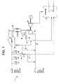
- a steam power plant 1 which includes a flowpath conduit, such as a steam pipeline 10, to couple the heat generator and the high pressure steam turbine (HPST) 30 with one another, and a main steam control valve (MSCV) 20, disposed along the piping upstream of the HPST 30, to admit the steam to the HPST 30 when a characteristic thereof satisfies a threshold.
- a flowpath conduit such as a steam pipeline 10
- HPST high pressure steam turbine
- MSCV main steam control valve
- the MSCV 20 includes temperature and pressure sensors, which are operationally coupled to the MSCV 20 and disposed within the steam pipeline 10 in respective positions with access to the steam.
- the power plant 1 includes an evacuator line 21 which is coupled to the steam pipeline 10 at a location between the MSCV 20 and the HPST 30 and which includes an evacuator valve 22.
- the evacuator line 21 is employed during the starting of the HPST 30 or the intermediate pressure steam turbine (IPST) 40 to control the thermal environment within the HPST 30 or the IPST 40 by removing steam from within the HPST 30 and the IPST 40 and dumping the removed steam into the condenser 70.
- IIPST intermediate pressure steam turbine
- a warming line 50 is coupled to the steam pipeline 10 at a location upstream of the MSCV 20 and terminating at a location downstream of the evacuator valve 22 on the evacuator line 21.
- the warming line 50 includes a warming line valve 55, which is opened to allow the warming line 50 to remove steam from the steam pipeline 10 and closed to prevent removal of steam from the steam pipeline 10.
- the steam being removed from the steam pipeline 10 causes increases in an amount of the steam flowing through the section of the steam pipeline 10 downstream of the location of the coupling of bypass line 12 with the steam pipeline 10. Due to the increased steam flow experienced by the section of the steam pipeline 10, the minimum conditions for the steam to be admitted to the HPST 30 is attained relatively quickly as compared to that of a power plant which does not include the warming line 50.
- the warming line 50 may be additionally or alternately coupled to the steam pipe 35 either directly or via the bypass line 12 which is coupled to the steam pipeline 10 at a location that is, in some cases, proximate to drain valves 80.
- the location of termination of warming line 50 would be upstream of the valve 13 with the provision of an additional pressure drop device 14 upstream of the location of connection so that, when the warming line valve 55 and bypass line valve 13 are each opened, warming steam can be transported to the bypass line 12 and then to steam pipe 35 from the steam pipeline 10.
- a method of operating a steam power plant 1 in which steam is received via a steam pipeline 10, including a valve 15, by at least one steam turbine 30, 40 for use in power generation includes removing a portion of the steam from the steam pipeline 10 downstream of the valve 15 and upstream from a main steam control valve (MSCV) 20, which is disposed along the steam pipeline 10 to admit the steam to the steam turbine 30, 40 when a characteristic thereof satisfies a threshold.
- the method further includes ceasing the removal of the portion of the steam and opening the MSCV 20 to admit the steam to the steam turbine 30, 40 when the characteristic satisfies the threshold.
- MSCV main steam control valve
- the schematic of the power plant 1 may be part of any combined cycle or Rankine cycle power plant.
Landscapes
- Engineering & Computer Science (AREA)
- Chemical & Material Sciences (AREA)
- Combustion & Propulsion (AREA)
- Mechanical Engineering (AREA)
- General Engineering & Computer Science (AREA)
- Control Of Turbines (AREA)
- Control Of Steam Boilers And Waste-Gas Boilers (AREA)
Applications Claiming Priority (1)
| Application Number | Priority Date | Filing Date | Title |
|---|---|---|---|
| US12/261,398 US7987675B2 (en) | 2008-10-30 | 2008-10-30 | Provision for rapid warming of steam piping of a power plant |
Publications (1)
| Publication Number | Publication Date |
|---|---|
| EP2390476A1 true EP2390476A1 (de) | 2011-11-30 |
Family
ID=42129782
Family Applications (1)
| Application Number | Title | Priority Date | Filing Date |
|---|---|---|---|
| EP09174107A Withdrawn EP2390476A1 (de) | 2008-10-30 | 2009-10-27 | Bereitstellung der schnellen Erwärmung von Dampfrohren eines Kraftwerks |
Country Status (4)
| Country | Link |
|---|---|
| US (1) | US7987675B2 (de) |
| EP (1) | EP2390476A1 (de) |
| JP (1) | JP2010106835A (de) |
| CN (1) | CN101725381B (de) |
Cited By (1)
| Publication number | Priority date | Publication date | Assignee | Title |
|---|---|---|---|---|
| US9845710B2 (en) | 2013-10-24 | 2017-12-19 | Kabushiki Kaisha Toshiba | Start-up method of steam turbine plant |
Families Citing this family (23)
| Publication number | Priority date | Publication date | Assignee | Title |
|---|---|---|---|---|
| US8381690B2 (en) | 2007-12-17 | 2013-02-26 | International Paper Company | Controlling cooling flow in a sootblower based on lance tube temperature |
| EP2430292A1 (de) | 2009-05-12 | 2012-03-21 | Icr Turbine Engine Corporation | Energiespeicherungs- und umwandlungssystem für gasturbinen |
| US8866334B2 (en) | 2010-03-02 | 2014-10-21 | Icr Turbine Engine Corporation | Dispatchable power from a renewable energy facility |
| US8984895B2 (en) | 2010-07-09 | 2015-03-24 | Icr Turbine Engine Corporation | Metallic ceramic spool for a gas turbine engine |
| CA2813680A1 (en) | 2010-09-03 | 2012-03-08 | Icr Turbine Engine Corporation | Gas turbine engine configurations |
| US8347598B2 (en) * | 2011-03-18 | 2013-01-08 | General Electric Company | Apparatus for starting up combined cycle power systems and method for assembling same |
| US9051873B2 (en) | 2011-05-20 | 2015-06-09 | Icr Turbine Engine Corporation | Ceramic-to-metal turbine shaft attachment |
| RU2556483C2 (ru) * | 2011-08-12 | 2015-07-10 | Мария Владимировна Еськова | Способ пуска паропровода перегретого пара в работу из холодного состояния |
| US10094288B2 (en) | 2012-07-24 | 2018-10-09 | Icr Turbine Engine Corporation | Ceramic-to-metal turbine volute attachment for a gas turbine engine |
| JP6173711B2 (ja) * | 2013-02-20 | 2017-08-02 | 三菱日立パワーシステムズ株式会社 | 蒸気タービンプラントおよびその運転方法 |
| JP5959454B2 (ja) * | 2013-03-08 | 2016-08-02 | 株式会社東芝 | 蒸気タービンシステム |
| CN103573304B (zh) * | 2013-11-12 | 2015-10-28 | 中国电力工程顾问集团西南电力设计院有限公司 | 采用过热度控制再热蒸汽管道上疏水阀的火电厂发电机组 |
| CN103573303B (zh) * | 2013-11-12 | 2015-10-28 | 中国电力工程顾问集团西南电力设计院有限公司 | 采用过热度控制主蒸汽管道疏水阀的火电厂发电机组 |
| JP6264128B2 (ja) * | 2014-03-20 | 2018-01-24 | 三菱日立パワーシステムズ株式会社 | コンバインドサイクルプラント、その制御方法、及びその制御装置 |
| EP2942493A1 (de) * | 2014-05-06 | 2015-11-11 | Siemens Aktiengesellschaft | Wasserdampfkreislauf sowie ein Verfahren zum Betreiben eines Wasserdampfkreislaufes |
| US10060688B2 (en) | 2014-07-25 | 2018-08-28 | Integrated Test & Measurement (ITM) | System and methods for detecting, monitoring, and removing deposits on boiler heat exchanger surfaces using vibrational analysis |
| US9927231B2 (en) * | 2014-07-25 | 2018-03-27 | Integrated Test & Measurement (ITM), LLC | System and methods for detecting, monitoring, and removing deposits on boiler heat exchanger surfaces using vibrational analysis |
| CA2955299C (en) | 2014-07-25 | 2017-12-12 | International Paper Company | System and method for determining a location of fouling on boiler heat transfer surface |
| CN104595520A (zh) * | 2015-01-01 | 2015-05-06 | 山西太钢不锈钢股份有限公司 | 一种防止大直径蒸气管道阀门卡涩的方法 |
| CN105673102B (zh) * | 2016-03-25 | 2017-02-08 | 鞍钢集团工程技术有限公司 | 两座焦炉产生蒸汽共用一套发电机组发电的方法 |
| KR101744314B1 (ko) * | 2016-06-22 | 2017-06-07 | 김건택 | 발전 장치 |
| JP6545737B2 (ja) * | 2017-02-23 | 2019-07-17 | 三菱重工業株式会社 | 発電システム及び発電システムの制御方法 |
| US20210341140A1 (en) | 2020-05-01 | 2021-11-04 | International Paper Company | System and methods for controlling operation of a recovery boiler to reduce fouling |
Citations (4)
| Publication number | Priority date | Publication date | Assignee | Title |
|---|---|---|---|---|
| DE1001286B (de) * | 1955-06-04 | 1957-01-24 | Sulzer Ag | Dampfkraftanlage mit Zwangsdurchlauf-Dampferzeuger |
| BE671323A (de) * | 1964-10-22 | 1966-02-14 | ||
| EP0605156A2 (de) * | 1992-12-30 | 1994-07-06 | General Electric Company | Methode zum Anfahren einer kalten Dampfturbine in einem Kombikraftwerk |
| DE4432960C1 (de) * | 1994-09-16 | 1995-11-30 | Steinmueller Gmbh L & C | Verfahren zum Betrieb eines Dampfkraftwerkes und Dampfkraftwerk |
Family Cites Families (5)
| Publication number | Priority date | Publication date | Assignee | Title |
|---|---|---|---|---|
| NL131057C (de) * | 1962-11-20 | |||
| US3972193A (en) * | 1975-01-02 | 1976-08-03 | Foster Wheeler Energy Corporation | Integral separator start-up system for a vapor generator with constant pressure furnace circuitry |
| JPS5572608A (en) * | 1978-11-29 | 1980-05-31 | Hitachi Ltd | Driving process of cross-compound turbine bypath system and its installation |
| JPS57179509A (en) * | 1981-04-28 | 1982-11-05 | Tokyo Shibaura Electric Co | Method of controlling temperature of superheated steam of boiler |
| JPS61237802A (ja) * | 1985-04-12 | 1986-10-23 | Hitachi Ltd | 蒸気タ−ビンの暖機方法 |
-
2008
- 2008-10-30 US US12/261,398 patent/US7987675B2/en not_active Expired - Fee Related
-
2009
- 2009-10-27 JP JP2009246002A patent/JP2010106835A/ja not_active Withdrawn
- 2009-10-27 EP EP09174107A patent/EP2390476A1/de not_active Withdrawn
- 2009-10-30 CN CN2009102088711A patent/CN101725381B/zh not_active Expired - Fee Related
Patent Citations (4)
| Publication number | Priority date | Publication date | Assignee | Title |
|---|---|---|---|---|
| DE1001286B (de) * | 1955-06-04 | 1957-01-24 | Sulzer Ag | Dampfkraftanlage mit Zwangsdurchlauf-Dampferzeuger |
| BE671323A (de) * | 1964-10-22 | 1966-02-14 | ||
| EP0605156A2 (de) * | 1992-12-30 | 1994-07-06 | General Electric Company | Methode zum Anfahren einer kalten Dampfturbine in einem Kombikraftwerk |
| DE4432960C1 (de) * | 1994-09-16 | 1995-11-30 | Steinmueller Gmbh L & C | Verfahren zum Betrieb eines Dampfkraftwerkes und Dampfkraftwerk |
Cited By (1)
| Publication number | Priority date | Publication date | Assignee | Title |
|---|---|---|---|---|
| US9845710B2 (en) | 2013-10-24 | 2017-12-19 | Kabushiki Kaisha Toshiba | Start-up method of steam turbine plant |
Also Published As
| Publication number | Publication date |
|---|---|
| US20100107636A1 (en) | 2010-05-06 |
| CN101725381B (zh) | 2013-03-27 |
| JP2010106835A (ja) | 2010-05-13 |
| US7987675B2 (en) | 2011-08-02 |
| CN101725381A (zh) | 2010-06-09 |
Similar Documents
| Publication | Publication Date | Title |
|---|---|---|
| US7987675B2 (en) | Provision for rapid warming of steam piping of a power plant | |
| CN101846311B (zh) | 预热热回收蒸汽发生器及相关联的蒸汽管道的系统和方法 | |
| JP5860597B2 (ja) | 排熱回収ボイラ配管を予熱するシステム及び方法 | |
| CN102213197B (zh) | 汽轮机设备 | |
| RU2586802C2 (ru) | Энергоустановка комбинированного цикла (варианты) | |
| CN103649474B (zh) | 蒸汽轮机设备和用于运行蒸汽轮机设备的方法 | |
| US8689557B2 (en) | Steam seal dump re-entry system | |
| CN203395585U (zh) | 超超临界机组的蒸汽主管道结构 | |
| JP7066572B2 (ja) | ボイラのブローイングアウト用仮設配管系統およびボイラのブローイングアウト方法 | |
| CN117329578A (zh) | 一种带有减温减压装置的锅炉蒸汽回收热汽系统 | |
| KR102512440B1 (ko) | 컴바인드 사이클 발전 플랜트 | |
| EP2850291B1 (de) | Kombikraftwerk zur energieerzeugung und verfahren zum betrieb des besagten kraftwerks | |
| JPH062806A (ja) | 給水加熱装置 | |
| CN103089435B (zh) | 包括热回收蒸汽发生器的联合循环发电设备 | |
| CN208332234U (zh) | 一种超临界锅炉系统的热态冲洗系统 | |
| CN105756721B (zh) | 用于产生功率的多级蒸汽涡轮 | |
| CN207815377U (zh) | 一种两段式蒸汽空气预热器 | |
| CN221825383U (zh) | 主凝结水系统 | |
| CN220134039U (zh) | 一种应用于汽轮发电机组灵活性改造的轴封漏汽旁路装置 | |
| CN114001348B (zh) | 一种热力系统 | |
| RU138055U1 (ru) | Маневренная парогазовая установка с многофункциональными парораспределительными узлами | |
| JPS59134307A (ja) | 蒸気タ−ビンプラント | |
| RU125258U1 (ru) | Маневренная парогазовая установка с байпасированными стопорными клапанами на главных паропроводах | |
| RU125259U1 (ru) | Маневренная парогазовая установка с редукционно-охладительной установкой на байпасе главной паровой задвижки | |
| SU1048134A1 (ru) | Теплова электрическа станци |
Legal Events
| Date | Code | Title | Description |
|---|---|---|---|
| AK | Designated contracting states |
Kind code of ref document: A1 Designated state(s): AT BE BG CH CY CZ DE DK EE ES FI FR GB GR HR HU IE IS IT LI LT LU LV MC MK MT NL NO PL PT RO SE SI SK SM TR |
|
| AX | Request for extension of the european patent |
Extension state: AL BA RS |
|
| PUAI | Public reference made under article 153(3) epc to a published international application that has entered the european phase |
Free format text: ORIGINAL CODE: 0009012 |
|
| 17P | Request for examination filed |
Effective date: 20111116 |
|
| GRAP | Despatch of communication of intention to grant a patent |
Free format text: ORIGINAL CODE: EPIDOSNIGR1 |
|
| INTG | Intention to grant announced |
Effective date: 20130624 |
|
| RIN1 | Information on inventor provided before grant (corrected) |
Inventor name: PANCHATSARAM, THILEEPAN Inventor name: BASHA, ASLAM |
|
| STAA | Information on the status of an ep patent application or granted ep patent |
Free format text: STATUS: THE APPLICATION IS DEEMED TO BE WITHDRAWN |
|
| 18D | Application deemed to be withdrawn |
Effective date: 20131106 |