EP2390620B2 - Capteur optoélectronique destiné à la détection de bords d'objets - Google Patents
Capteur optoélectronique destiné à la détection de bords d'objets Download PDFInfo
- Publication number
- EP2390620B2 EP2390620B2 EP11004261.1A EP11004261A EP2390620B2 EP 2390620 B2 EP2390620 B2 EP 2390620B2 EP 11004261 A EP11004261 A EP 11004261A EP 2390620 B2 EP2390620 B2 EP 2390620B2
- Authority
- EP
- European Patent Office
- Prior art keywords
- light
- sensor
- receivers
- light receivers
- accordance
- Prior art date
- Legal status (The legal status is an assumption and is not a legal conclusion. Google has not performed a legal analysis and makes no representation as to the accuracy of the status listed.)
- Active
Links
Images

Classifications
-
- G—PHYSICS
- G01—MEASURING; TESTING
- G01B—MEASURING LENGTH, THICKNESS OR SIMILAR LINEAR DIMENSIONS; MEASURING ANGLES; MEASURING AREAS; MEASURING IRREGULARITIES OF SURFACES OR CONTOURS
- G01B11/00—Measuring arrangements characterised by the use of optical techniques
- G01B11/02—Measuring arrangements characterised by the use of optical techniques for measuring length, width or thickness
- G01B11/028—Measuring arrangements characterised by the use of optical techniques for measuring length, width or thickness by measuring lateral position of a boundary of the object
-
- G—PHYSICS
- G01—MEASURING; TESTING
- G01B—MEASURING LENGTH, THICKNESS OR SIMILAR LINEAR DIMENSIONS; MEASURING ANGLES; MEASURING AREAS; MEASURING IRREGULARITIES OF SURFACES OR CONTOURS
- G01B11/00—Measuring arrangements characterised by the use of optical techniques
- G01B11/24—Measuring arrangements characterised by the use of optical techniques for measuring contours or curvatures
- G01B11/245—Measuring arrangements characterised by the use of optical techniques for measuring contours or curvatures using a plurality of fixed, simultaneously operating transducers
Definitions
- the present invention relates to an optoelectronic sensor for detecting object edges of objects moving relative to the sensor according to the features of the preamble of independent claim 1.
- an optoelectronic sensor is known from the document US 5,841,540 . US 4,217,491 . JP 58-223004 A or US 5,280,171 known.
- optoelectronic sensors are used to detect along a conveyor belt transported packaging, such as beverage cartons, for subsequent processing, such as an application of a straw to recognize.
- packaging such as beverage cartons
- the packages are not isolated here, but follow each other so closely that when passing the packaging on the sensor, the transition from one packaging to the next packaging with a conventional Triangulationstaster with spatially resolving light receiver whose basic operation is well known and therefore not here is difficult to see, as explained below Fig. 1 is clarified.
- Fig. 1a shows a plan view of several directly behind each other arranged beverage cartons 11, which move on a conveyor belt on a triangulation probe, and a diagram of the associated desired course of the switching signal of the triangulation probe.
- Fig. 1b shows a section of a side view of the beverage cartons 11 Fig. 1a and a scanning trace 13 of a light spot generated by the transmitted light beam of the triangulation probe on the beverage cartons 11.
- Fig. 1c shows the recorded course of a position signal X and the corresponding course of an intensity signal I of the button.
- the scanning trace 13 has text printed in black on the beverage cartons, i. ultimately over an inhomogeneous texture, so that the center of gravity of an image of the light spot recorded by the light receiver and thus the position signal X varies correspondingly, as shown at 17.
- a glossy area, through which the light is at least partially reflected, or a displacement of a beverage carton perpendicular to the conveying direction may interfere with the intensity signal I, as shown at 19 and 21, respectively. Consequently, these sources of error can cause a higher signal swing than a transition between two successive beverage cartons, so that the edges of the beverage cartons are not robustly detectable.
- the transition between two consecutive objects can be recognized in particular on the basis of the rear object edge of the front object in the direction of movement and / or the front edge of the rear object.
- the two light receivers are preferably arranged in a receiver plane formed in particular by the light-emitting device and the two light receivers, in particular running horizontally, which extends transversely, in particular perpendicularly, to the alignment of the object edges.
- the respective transmitted light beam is oriented, for example, at least substantially parallel to a normal of a flat side of the object facing the sensor, at least approximately the same amount of light is incident on the two light receivers, i. the two light receivers detect at least approximately the same reception intensity (balanced state). If the transmitted light beam hits the rear edge, more light falls on the rear light receiver in the direction of movement and less light on the front light receiver than in the balanced state. For the front edge, this is just the opposite.
- the two light receivers thus represent a kind of energetic balance which, depending on whether it is a rear or anterior object edge, can deflect in different directions.
- An evaluation of the result of a respective comparison comprises according to the invention that the result of the respective comparison is common to one or more results of one or more other comparisons Is evaluated. If the evaluation is based on a single result, eg a difference between the two reception intensities, the evaluation can, for example, consist in a comparison of the difference with a threshold value.
- Such a sensor can achieve a considerable cost advantage over the realizations known from the prior art.
- Such a sensor allows high switching frequencies with relatively low power consumption, and can be built in a relatively small size.
- the evaluation unit is designed to jointly evaluate the results of the comparisons of at least two recordings, with the combined evaluation preferably taking place continuously or chronologically.
- a recording is a recording of the recorded by the two light receiver two images of the light spot of the transmitted light beam of a light transmitter to understand.
- the conveying speed of the objects is known, with known gap width to be recognized then it is also known with which temporal offset after the detection of a potential trailing edge a leading edge should be detected so that the robustness of the edge detection can be increased even with only one light transmitter ,
- the at least two recordings take place one after the other or at least two different times.
- the time interval between the at least two recordings can be within a predetermined time interval.
- the at least two recordings are made by the at least two light transmitters.
- two images are evaluated together, which in this case are not assigned to a single light emitter, whose light spot successively captures at least two images, but at least two light emitters, by which the at least two images can be recorded at least substantially simultaneously, wherein “substantially” refers in particular to alternately controlled light emitter.
- a potential leading edge through the one light emitter
- a potential trailing edge through the other light emitter
- the conveying speed of the objects need not be known here.
- the two light receivers and the light emitter (s) are arranged in a line arrangement or arranged in a row and / or arranged in the aforementioned receiver plane.
- a difference can be formed from the optionally weighted two individual differences (the reception intensities recorded by the two light receivers) received at the at least two different times and / or by the at least two light transmitters, and this difference can be compared to a threshold value.
- an algorithm can also be used in general, by means of which the two individual differences can be compared with one another and evaluated jointly.
- the senor can be designed to adapt the time interval between the at least two recordings and / or the distance of the at least two light transmitters from each other to a predetermined, expected distance between two adjacent objects or a predetermined width of a gap formed between two adjacent objects.
- the sensor can thereby be adjusted to different gap widths, in particular the desired gap width to be detected.
- the at least two light receivers are purely energetic receivers, i. to recipients who have no spatial resolution.
- Such receivers offer a cost advantage over spatially resolved light receivers.
- the sensor is designed to control the at least two light emitters alternately, so that a distinction of the images of different light emitters is possible. If light receivers are provided with spatial resolution, preferably only the reception intensities and no distance information are evaluated by the evaluation unit.
- an even number of light receivers is provided, wherein at least four light receivers are provided, wherein each two light receivers form a pair of light receivers, and wherein the two light receivers of a respective pair are arranged on the two opposite sides of the light emitting device, wherein preferably the evaluation unit for is designed to use for the detection of object edges only a selected one or more selected pairs, in particular, the number of selected pairs is less than the number of existing pairs.
- the pair or pairs of light receivers that are best suited for edge detection can be selected. If several pairs are selected, it is preferable if the results of the multiple pairs are compared with one another and evaluated or evaluated together. In particular, the pairs are arranged in mutually parallel receiver planes or one above the other.
- the selection of at least one of the reception intensities of the two images recorded by the two light receivers of the respective pair may therefore be preferable for the selection of at least one of the reception intensities of the two images recorded by the two light receivers of the respective pair to be dependent, preferably a pair not being selected if the at least one of the reception intensities exceeds a predetermined upper threshold and / or falls below a predetermined lower threshold.
- At least one further, in particular at least two further, spatially resolving light receivers are / are provided.
- the two other light receivers may be arranged on the other two opposite sides of the light emitting device.
- the evaluation unit is preferably configured to calculate the two distances determined by means of triangulation from the positions of the two images of the respective light spot recorded by the two further light receivers and to evaluate the result of the respective offsetting, in which case a particular weighting is preferred for the respective offsetting Mean value is formed from the two distances.
- the weighting preferably depends on the two reception intensities of the two images of the respective light spot picked up by the two further light receivers, the relative weighting of the distance determined from the position of the respective image preferably being smaller, the greater the relative reception intensity of the respective image.
- the "disturbed" light receiver then has an increased reception intensity compared to the other further light receiver, so that - if an increased reception intensity is determined - the corresponding distance in the averaging can be weighted less.
- the invention also relates to an optoelectronic sensor for detecting object edges of objects moving relative to the sensor, having a light emitting device with at least one light transmitter, in particular at least two light transmitters, for generating a respective collimated or focused transmitted light beam, with at least two light receivers for receiving one through the the respective transmitted light beam on a respective object generated light spot, wherein the two light receivers are arranged on two opposite sides of the light emitting device, and with an evaluation unit, which is adapted for, by means of triangulation from the positions of the two light receivers taken two images of the respective light spot certain two distances to each other and to evaluate the result of each offsetting to detect an object edge, wherein the respective allocation a weighted average of the two Ab Stands is formed, and wherein the weighting of the two reception intensities of the two further light receiver recorded two images of the respective light spot depends.
- the evaluation unit is designed to jointly evaluate the results of the billing for the at least two light transmitters. This makes it possible, in particular, to avoid a disturbance in the edge detection by an object displaced perpendicular to the conveying direction relative to the other objects, since this can be used to detect when the light spots assigned to the at least two light transmitters fall on different objects.
- the sensor is designed to control the at least two light transmitters alternately, so that it is possible to distinguish the reception intensities and determined distances of different light transmitters.
- the light emitting device and the at least two light receivers and / or at least two further light receivers each comprise a polarizing filter, wherein preferably all the polarizing filters of the sensor are either linear polarizing filters or circular polarizing filters and / or preferably the polarization direction of the polarizing filter of the respective light receiver and / or respective other light receiver of the polarization direction of the polarization filter of the light emitting device is at least substantially opposite or corresponds.
- the respective transmitted light beam is linearly polarized. In a reflection on an object, the polarization of the light is retained, in a remission, the polarization is lost.
- the respective transmitted light beam is circularly polarized in one of two directions of rotation, left or right.
- the direction of rotation of the polarization of the light is reversed or rotated, in a remission, the polarization is lost.
- the polarization filter having the same direction of rotation can in turn at least largely hide reflected light.
- the present invention further relates to a method according to claim 12.
- Preferred embodiments of the method according to the invention result in an analogous manner from the preferred embodiments of the image sensor according to the invention.
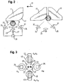
- the in Fig. 2 Sensor shown comprises a light emitting device with a light transmitter 23 and two in a receiver plane at least substantially symmetrical to both sides, ie left and right of the light emitter 23 arranged light receiver 25.
- the transmitted light beam 31 generates a light spot.
- the transmitted light beam 31 is at least substantially perpendicular to the sides of the beverage cartons 11 facing the sensor.
- the Lambert-characteristic light remitted at the location of the light spot returns to the sensor as received light beams 35 and is detected by receiving lenses 37 in the light receivers 25.
- the light receivers 25 are purely energetic receivers without spatial resolution, so that only the reception intensities of the images of the light spot recorded by the light receivers 25 are detected there.
- a connected to the light transmitter 23 and the light receivers 25 control and evaluation unit 39 is provided to control the light emitter 23 and to evaluate the aforementioned reception intensities.
- the reception intensity detected by the front light receiver 25 in the conveying direction 33 corresponds at least approximately to the reception intensity detected by the rear light receiver 25 in the conveying direction 33, since this is at least approximately the same a lot of light falls on the two light receivers 25.
- An edge 41 is therefore not available. If, however, the transmitted light beam 31 impinges on the beverage carton 11 in the region of the edge 41 (right image), considerably more light falls on the rear light receiver 25 in the conveying direction 33, so that the reception intensities of the two light receivers 25 differ significantly from one another ,
- the difference between the two reception intensities can therefore be used as a criterion for the presence of an edge 41.
- the criterion is met if the difference exceeds a predetermined threshold.
- the front edge 41 of a beverage carton 11 follows with a certain time interval, the limits of which are the conveying speed of the beverage cartons 11 and the potential distances of the beverage cartons 11 to each other, the front edge 41 of the next beverage carton 11, the difference for the two Edges 41 has opposite signs.
- the robustness of the gap or edge detection can be increased even further by the evaluation criterion as to whether a front edge 41 follows a rear edge 41 within a predetermined time interval.
- the difference between the difference for the trailing edge 41 and the difference for the leading edge 41 can be formed and compared with a threshold value, wherein the criterion for the presence of a gap or a front and rear edge 41 is met when the threshold value is exceeded ,
- the sign of this superordinate difference depends on the conveying direction 33.
- FIG. 3 Simplified sensor shown is a development of in Fig. 2 shown sensor. Notwithstanding the in Fig. 2 The sensor shown in FIG Fig. 3 not just one, but two light emitters 23, which are driven alternately and which are arranged together with the two light receivers 25 in a horizontal row, and additionally two further, spatially resolving light receiver 43 with receiving lenses 45.
- the two light emitters 23 comprise two light sources 27 and one common transmission lens 29.
- two transmitting lenses can also be provided, or merely one light source, from the light beams of which two transmitted light beams are subsequently generated.
- the light transmitters 23 are preferably lasers or LEDs.
- the two light receivers 25 only provide reception intensities, the two other light receivers 43 each additionally a position or distance information.
- the two light receivers 25 can also be designed as spatially resolving light receivers and / or provide position information or distance information.
- the two further light receivers 43 are arranged at least substantially symmetrically above and below the light-emitting device or in a further receiver plane which is perpendicular to the receiver plane formed by the light transmitters 23 and the light receivers 25. In the rear view shown, the light receiver 25 and the other light receiver 43 are circular, each offset by 90 ° from each other to the light emitting device distributed.
- the further light receivers 43 may be, for example, single-line image sensors or image sensors with pixel matrix, or PIN diodes.
- the two light receivers 25 have a sufficiently large receiving surface in order to record the images of both the light spot of the transmitted light beam 31 of the first light emitter 23 and the light spot of the transmitted light beam 31 of the second light emitter 23.
- the corresponding criterion for the presence of an object is: e L 1 - e R 1 e L 1 + e R 1 + M - e L 2 - e R 2 e L 2 + e R 2 + M ⁇ limit 1, where E L1 is the reception intensity of the left light receiver for the first light transmitter, E R1 is the reception intensity of the right light receiver for the first light transmitter, E L2 is the reception intensity of the left light receiver for the second light transmitter and E R2 is the reception intensity of the right light receiver for the second light transmitter, and where M ⁇ 0, which is to prevent a division by 0 at reception intensities of 0.
- This difference assumes, with simultaneous detection of the two edges 41, a maximum value which corresponds to the sum of the amount of the difference for the leading edge 41 and the amount of the difference for the trailing edge 41 and which exceeds the limit value 1, so that the criterion for the presence of a gap 41 is fulfilled.
- the sign of this difference is independent of the conveying direction 33.
- first or second light emitter 23 and the other two light receiver 43 two triangulation are realized by each of the distance of a beverage carton 11 can be calculated by the sensor. Since the further light receivers 43 are arranged symmetrically about the light transmitters 23, a disturbance of the two calculated distances caused by an inhomogeneous texture on the respective beverage carton 11 can be compensated. For this purpose, an average value is formed from the two calculated distances, since with the associated addition, the errors caused by the disturbance in the two calculated distances at least largely cancel each other out.
- the two calculated distances can be weighted.
- the weighting of the respective calculated distance is greater, the smaller the relative reception intensity on the respective further light receiver 43. This is particularly advantageous because it lessens a calculated distance which is defective due to a gloss effect.
- the object distance can be determined with particular accuracy and thus a particularly robust background suppression can be achieved.
- the corresponding criterion for the presence of an object is then: 1 2 X O 1 e U 1 e O 1 + e U 1 + X U 1 e O 1 e O 1 + e U 1 ⁇ limit 2, where E U1 is the reception intensity of the lower light receiver for the first light transmitter, E O1 is the reception intensity of the upper light receiver for the first light transmitter, X O1 is the determined distance of the upper light receiver for the first light transmitter, and X U1 is the determined distance of the lower light receiver for the first light transmitter is.
- the corresponding criterion for the presence of an object in this case is: X O 1 e U 1 e O 1 + e U 1 + X U 1 e O 1 e O 1 + e U 1 - X O 2 e U 2 e O 2 + e U 2 + X U 2 e O 2 e O 2 + e U 2 ⁇ limit 3, where E U2 is the reception intensity of the lower light receiver for the second light transmitter, E O2 is the reception intensity of the upper light receiver for the second light transmitter, X O2 is the determined distance of the upper light receiver for the second light transmitter and X U2 is the determined distance of the lower light receiver for the second Light transmitter is.
- a criterion for the presence of an object is set up, which adjusts to the total energy received by the two further light receivers 43: e U + e O > limit 4, where Eu is the reception intensity of the lower light receiver for the first and / or second light emitter and Eo is the reception intensity of the upper light receiver for the first and / or second light emitter.
- the sensor according to Fig. 3 is preferably formed such that an object detection signal is output, that is, that the presence of a beverage carton 11 is recognized when the conditions (1) to (4) are satisfied. If at least one of the stated conditions is not fulfilled, there is a transition between two successive beverage cartons 11 or an edge 41 is detected.
Landscapes
- Physics & Mathematics (AREA)
- General Physics & Mathematics (AREA)
- Length Measuring Devices By Optical Means (AREA)
Claims (12)
- Capteur optoélectronique pour reconnaître des arêtes sur des objets en déplacement par rapport au capteur,
comprenant un système émetteur de lumière avec au moins un émetteur de lumière (23), en particulier au moins deux émetteurs de lumière, pour engendrer un faisceau de lumière émise (31) respectif collimaté ou focalisé, comprenant au moins deux récepteurs de lumière (25) pour prendre un vue d'une tache lumineuse engendrée sur un objet (11) par le faisceau de lumière émise respectif (31), les deux récepteurs de lumière (25) étant agencés sur des côtés mutuellement opposés du système émetteur de lumière, et
comprenant une unité d'évaluation (39) qui est réalisée pour comparer l'une à l'autre deux intensités de réception des deux images, prises par les deux récepteurs de lumière (25), de la tache lumineuse respective, et d'évaluer le résultat de la comparaison respective afin de reconnaître une arête (41) d'un objet,
caractérisé en ce que
l'évaluation du résultat de la comparaison respective inclut d'évaluer le résultat de la comparaison respective conjointement avec un ou plusieurs résultats d'une ou de plusieurs autres comparaisons,
et en ce que l'unité d'évaluation est réalisée pour évaluer conjointement les résultats des comparaisons d'au moins deux prises de vue, dans lesquelles une prise de vue est une prise de vue des deux images, prises par lesdits au moins deux récepteurs de lumière, de la tache lumineuse du faisceau de lumière émise dudit au moins un émetteur de lumière. - Capteur selon la revendication 1,
caractérisé en ce que lesdites au moins deux prises de vue ont lieu temporellement l'une après l'autre et/ou au moyen desdits au moins deux émetteurs de lumière (23). - Capteur selon la revendication 2,
caractérisé en ce que
le capteur est réalisé pour adapter l'écart temporel entre lesdites au moins deux prises de vue et/ou la distance desdits au moins deux émetteurs de lumière (23) l'un par rapport à l'autre à une distance prédéterminée attendue entre deux objets voisins (11). - Capteur selon l'une au moins des revendications précédentes,
caractérisé en ce qu'il est prévu un nombre pair de récepteurs de lumière (25), de sorte qu'il est prévu au moins quatre récepteurs de lumière (25), dans lesquels deux récepteurs de lumière respectifs (25) forment une paire de récepteurs de lumière (25), et dans lesquels les deux récepteurs de lumière (25) d'une paire respective sont agencés sur les deux côtés mutuellement opposés du système émetteur de lumière, et l'unité d'évaluation (39) est de préférence réalisée, pour la reconnaissance d'arêtes (41) sur les objets, pour utiliser seulement une paire choisie ou plusieurs paires choisies, et le nombre des paires choisies est en particulier plus faible que le nombre des paires présentes. - Capteur selon la revendication 4,
caractérisé en ce que
le choix dépend d'au moins une des intensités de réception des deux images prises par les deux récepteurs de lumière (25) de la paire respective, et de préférence une paire n'est pas choisie lorsque ladite au moins une des intensités de réception dépasse une valeur seuil supérieure prédéterminée et/ou passe au-dessous d'une valeur seuil inférieure prédéterminée. - Capteur selon l'une au moins des revendications précédentes,
caractérisé en ce que
les deux récepteurs de lumière (25) et le ou les émetteurs de lumière (23) sont prévus dans un agencement en ligne et/ou en ce que le capteur est réalisé pour piloter lesdits au moins deux émetteurs de lumière (23) en alternance. - Capteur selon l'une au moins des revendications précédentes,
caractérisé en ce que
il est prévu au moins un autre récepteur de lumière à résolution locale (43), en particulier au moins deux autres récepteurs de lumière, et les deux autres récepteurs de lumière (43) sont agencés de préférence sur les deux autres côtés mutuellement opposés du système émetteur de lumière. - Capteur selon la revendication 7,
caractérisé en ce que
l'unité d'évaluation (39) est réalisée pour combiner par calcul l'une avec l'autre deux distances déterminées au moyen d'une triangulation à partir des situations des deux images, prises par les deux autres récepteurs de lumière (43), de la tache lumineuse respective, et pour évaluer le résultat du calcul respectif et de préférence lors de ce calcul, une valeur moyenne, en particulier pondérée, est formée à partir des deux distances. - Capteur selon la revendication 8,
caractérisé en ce que
la pondération dépend des deux intensités de réception des deux images, prises par les deux autres récepteurs de lumière (43), de la tache lumineuse respective, et de préférence la pondération relative de la distance déterminée à partir de la position de l'image respective est d'autant plus faible que l'intensité de réception relative de l'image respective est plus forte. - Capteur selon la revendication 8 ou 9,
caractérisé en ce que
l'unité d'évaluation (39) est réalisée pour évaluer en commun les résultats des calculs pour lesdits au moins deux émetteurs de lumière (23). - Capteur selon l'une au moins des revendications précédentes,
caractérisé en ce que
le système émetteur de lumière et lesdits au moins deux récepteurs de lumière (25) et/ou lesdits au moins deux autres récepteurs de lumière (43) incluent chacun un filtre à polarisation, et de préférence la totalité des filtres à polarisation du capteur sont soit des filtres à polarisation linéaire soit des filtres à polarisation circulaire, et/ou dans lequel la direction de polarisation du filtre à polarisation de récepteurs de lumière respectifs et/ou des autres récepteurs de lumière respectifs correspond ou est opposée de préférence à la direction de polarisation du filtre à polarisation du système émetteur de lumière. - Procédé pour la détection d'arêtes sur des objets déplacés par rapport à un capteur optoélectronique, dans lequel au moins un faisceau de lumière émise et en particulier deux faisceaux de lumière émise respectivement collimatés ou focalisés sont engendrés par un système émetteur de lumière,
un vue d'une tache lumineuse engendrée sur un objet par le faisceau de lumière émise respectif est prise par deux récepteurs de lumière agencés sur des côtés mutuellement opposés du système émetteur de lumière,
les deux intensités de réception des deux images, prises par les deux récepteurs de lumière, de la tache lumineuse respective sont comparées l'une à l'autre et le résultat de la comparaison respective est évalué afin de reconnaître une arête d'un objet,
caractérisé en ce que
l'évaluation du résultat de la comparaison respective inclut d'évaluer le résultat de la comparaison respective conjointement avec un ou plusieurs résultats d'une ou de plusieurs autres comparaisons,
et les résultats des comparaisons d'au moins deux prises de vue sont évalués conjointement, une prise de vue étant une prise de vue des deux images, prises par lesdits au moins deux récepteurs de lumière, de la tache lumineuse du faisceau de lumière émise dudit au moins un émetteur de lumière.
Applications Claiming Priority (1)
| Application Number | Priority Date | Filing Date | Title |
|---|---|---|---|
| DE102010022273A DE102010022273A1 (de) | 2010-05-31 | 2010-05-31 | Optoelektronischer Sensor zur Detektion von Objektkanten |
Publications (4)
| Publication Number | Publication Date |
|---|---|
| EP2390620A1 EP2390620A1 (fr) | 2011-11-30 |
| EP2390620B1 EP2390620B1 (fr) | 2014-10-29 |
| EP2390620B2 true EP2390620B2 (fr) | 2018-02-21 |
| EP2390620B9 EP2390620B9 (fr) | 2018-05-23 |
Family
ID=44259787
Family Applications (1)
| Application Number | Title | Priority Date | Filing Date |
|---|---|---|---|
| EP11004261.1A Active EP2390620B9 (fr) | 2010-05-31 | 2011-05-24 | Capteur optoélectronique destiné à la détection de bords d'objets |
Country Status (3)
| Country | Link |
|---|---|
| US (1) | US8963113B2 (fr) |
| EP (1) | EP2390620B9 (fr) |
| DE (1) | DE102010022273A1 (fr) |
Families Citing this family (18)
| Publication number | Priority date | Publication date | Assignee | Title |
|---|---|---|---|---|
| DE102010022273A1 (de) | 2010-05-31 | 2011-12-01 | Sick Ag | Optoelektronischer Sensor zur Detektion von Objektkanten |
| DE202012012550U1 (de) | 2012-04-26 | 2013-05-08 | Sick Ag | Sensor zur Erfassung von Objekten auf einer Überwachungsstrecke |
| EP2801786B1 (fr) | 2013-05-08 | 2019-01-02 | Sick AG | Capteur optoélectronique et procédé pour la détection de bords d'objets |
| DE202013105533U1 (de) | 2013-12-05 | 2015-03-10 | Sick Ag | Optoelektronischer Sensor |
| DE102014105746C5 (de) | 2013-12-05 | 2020-12-24 | Sick Ag | Optoelektronischer Sensor und Verfahren zur Erfassung glänzender Objekte |
| EP3105939B1 (fr) * | 2014-02-11 | 2020-05-20 | VEGA Grieshaber KG | Système de mesure et procédé pour détecter des propriétés d'un objet |
| JP5789010B2 (ja) * | 2014-02-13 | 2015-10-07 | Dmg森精機株式会社 | 表面形状測定装置およびそれを備えた工作機械 |
| EP2963444B1 (fr) | 2014-07-03 | 2019-08-28 | Sick Ag | Capteur et procédé de détection à un endroit précis d'un objet transporté dans une direction de transport, par rapport à un capteur |
| DE202014103068U1 (de) | 2014-07-03 | 2015-10-12 | Sick Ag | Sensor zur ortsgenauen Detektion eines relativ zum Sensor in eine Förderrichtung geförderten Objekts |
| ES2619422T3 (es) * | 2014-08-15 | 2017-06-26 | Sick Ag | Rejilla de luz |
| DE102015105149B4 (de) * | 2015-04-02 | 2018-10-11 | Sick Ag | Optoelektronischer Sensor |
| JP6046852B1 (ja) * | 2016-07-06 | 2016-12-21 | 株式会社エクサ | 形状解析プログラム |
| US11274856B2 (en) | 2017-11-16 | 2022-03-15 | Ari Peter Berman | Method of deploying a heat exchanger pipe |
| US11772223B2 (en) | 2019-05-17 | 2023-10-03 | Vitaly Tsukanov | Systems for blade sharpening and contactless blade sharpness detection |
| DE102019117849B4 (de) * | 2019-07-02 | 2023-06-15 | Sick Ag | Erfassung eines Objekts in einem Überwachungsbereich |
| US11904428B2 (en) | 2019-10-25 | 2024-02-20 | Vitaly Tsukanov | Systems for blade sharpening and contactless blade sharpness detection |
| EP4202494B1 (fr) | 2021-12-21 | 2024-01-31 | Sick Ag | Détection optique d'un objet selon le principe de triangulation |
| DE102022101680B4 (de) | 2022-01-25 | 2023-09-21 | Sick Ag | Optoelektronischer Sensor und Verfahren zum Erfassen eines Objekts |
Citations (11)
| Publication number | Priority date | Publication date | Assignee | Title |
|---|---|---|---|---|
| US4112309A (en) † | 1975-11-22 | 1978-09-05 | Nippon Kogaku K.K. | Apparatus for measuring the line width of a pattern |
| US4217491A (en) † | 1978-06-29 | 1980-08-12 | Nolan Systems Inc. | Counting system for articles conveyed in a stream |
| JPS58223004A (ja) † | 1982-06-21 | 1983-12-24 | Hitachi Ltd | 段差の山谷識別装置 |
| US5280171A (en) † | 1992-05-06 | 1994-01-18 | Baumer Electric Ag | Process and apparatus for the non-contacting detection of edges of objects |
| DE19634186A1 (de) † | 1995-08-28 | 1997-03-06 | Siemens Ag Oesterreich | Netzgeführte Thyristorbrücke |
| US5841540A (en) † | 1995-06-07 | 1998-11-24 | Siemens Electrocom L.P. | Dichotomous scan system for detection of edges of objects and overlapped objects having relatively uniform surfaces |
| DE19808215A1 (de) † | 1998-02-27 | 1999-09-16 | Leuze Electronic Gmbh & Co | Optoelektronische Vorrichtung |
| DE19852173A1 (de) † | 1998-11-12 | 2000-05-31 | Leuze Electronic Gmbh & Co | Lichttaster |
| EP1041393B1 (fr) † | 1999-04-01 | 2004-06-02 | Leuze electronic GmbH + Co KG | Dispositif optoélectronique |
| EP1801618A2 (fr) † | 2005-12-24 | 2007-06-27 | Leuze electronic GmbH + Co. KG | Dispositif optoélectronique |
| DE202008017457U1 (de) † | 2008-04-09 | 2009-08-27 | Leuze Electronic Gmbh + Co. Kg | Sensoranordnung zur Erfassung von Objekten |
Family Cites Families (40)
| Publication number | Priority date | Publication date | Assignee | Title |
|---|---|---|---|---|
| US3892492A (en) * | 1972-10-16 | 1975-07-01 | Loepfe Ag Geb | Optoelectrical apparatus with directional light sources for detecting reflection behaviour of an object |
| US3885872A (en) * | 1973-06-12 | 1975-05-27 | Ibm | Digital proximity sensing system |
| JPS5516278A (en) * | 1978-07-21 | 1980-02-04 | Giken Toreeteingu Kk | Method of counting number of passengers |
| US5114230A (en) * | 1979-09-07 | 1992-05-19 | Diffracto Ltd. | Electro-optical inspection |
| US4296314A (en) * | 1979-11-26 | 1981-10-20 | Rockwell International Corporation | Non-contact counter |
| SE433200B (sv) * | 1980-06-04 | 1984-05-14 | Dagens Nyheters Ab | Sett och anordning for att rekna fiskfjellsartat lagda foremal |
| JPS5793208A (en) * | 1980-12-01 | 1982-06-10 | Nippon Kogaku Kk <Nikon> | Optical system of distance measuring apparatus |
| US4481667A (en) * | 1981-12-21 | 1984-11-06 | Autronics Corporation | Item counting apparatus |
| US4559452A (en) * | 1982-06-02 | 1985-12-17 | Fujitsu Limited | Apparatus for detecting edge of semitransparent plane substance |
| US4540887A (en) * | 1983-01-28 | 1985-09-10 | Xerox Corporation | High contrast ratio paper sensor |
| JPS63235909A (ja) * | 1987-03-24 | 1988-09-30 | Fuji Photo Optical Co Ltd | アクテイブ型オ−トフオ−カス機構 |
| US4845374A (en) * | 1987-07-20 | 1989-07-04 | R. J. Reynolds Tobacco Company | Method and apparatus for detecting the deposition of an adhesive on a travelling web |
| DE3729334A1 (de) | 1987-09-02 | 1989-03-16 | Sick Optik Elektronik Erwin | Lichttaster |
| FI87696C (fi) * | 1991-09-30 | 1993-02-10 | Valtion Teknillinen | Foerfarande i en med optisk princip fungerande ankomstkoppling |
| US5245177A (en) * | 1991-10-24 | 1993-09-14 | Schiller Norman H | Electro-optical system for detecting the presence of an object within a predetermined detection system |
| US5504345A (en) * | 1994-04-14 | 1996-04-02 | Hama Laboratories, Inc. | Dual beam sensor and edge detection system and method |
| US5614710A (en) * | 1995-06-07 | 1997-03-25 | Electrocom Automation L.P. | Dichotomous scan system for detection of overlapped objects |
| DE19624186A1 (de) * | 1996-06-18 | 1998-01-02 | Philips Patentverwaltung | Kantendetektoreinrichtung |
| CH693468A5 (de) | 1998-12-16 | 2003-08-15 | Hera Rotterdam Bv | Verfahren und Vorrichtung für die Detektion oder Lagebestimmung von Kanten. |
| US6175419B1 (en) | 1999-03-24 | 2001-01-16 | Fife Corporation | Light sensor for web-guiding apparatus |
| JP3456930B2 (ja) * | 1999-07-16 | 2003-10-14 | サンクス株式会社 | 板状部材検出装置 |
| JP2001221610A (ja) * | 2000-02-04 | 2001-08-17 | Sunx Ltd | 反射型センサ |
| US6400460B1 (en) * | 2000-04-10 | 2002-06-04 | Honeywell International Inc. | Multifunction optical sensor with variable detection threshold and noise suppression |
| US6618155B2 (en) * | 2000-08-23 | 2003-09-09 | Lmi Technologies Inc. | Method and apparatus for scanning lumber and other objects |
| JP2004117161A (ja) * | 2002-09-26 | 2004-04-15 | Sharp Corp | 光学式変位センサ |
| DE10246449A1 (de) * | 2002-10-04 | 2004-06-09 | Kleinhuber, Harald G. | Sensorsystem zum Erkennen der Lage von ringförmigen Einprägungen an Materialbahnen |
| US6850264B2 (en) * | 2003-01-28 | 2005-02-01 | Fujifilm Electronic Imaging Limited | Edge detection apparatus and method |
| US7161586B2 (en) * | 2003-07-01 | 2007-01-09 | Em Microelectronic-Marin Sa | Method of operating an optical motion sensing device and optical motion sensing device implementing this method |
| ITBZ20040044A1 (it) * | 2004-08-24 | 2004-11-24 | Microtec Srl | Componente modulare per dispositivi per effettuare in un sistema di coordinate cartesiane la ricostruzione virtuale tridimensionale di superfici di corpi come pure un tale dispositivo comprendente una pluralita' di componenti modulari. |
| US20070024870A1 (en) * | 2005-08-01 | 2007-02-01 | Girard Mark T | Apparatuses and methods for measuring head suspensions and head suspension assemblies |
| JP4757136B2 (ja) * | 2005-08-31 | 2011-08-24 | キヤノン株式会社 | 記録装置および制御方法 |
| US7652767B2 (en) * | 2006-10-19 | 2010-01-26 | Sporian Microsystems, Inc. | Optical sensor with chemically reactive surface |
| US7602496B2 (en) * | 2006-10-19 | 2009-10-13 | Sporian Microsystems, Inc. | Optical sensor with biologically reactive surface |
| WO2008133650A2 (fr) * | 2006-11-07 | 2008-11-06 | Rudolph Technologies, Inc. | Procédé et système pour fournir un système de triangulation haute définition |
| US7684053B2 (en) * | 2006-12-12 | 2010-03-23 | Hong Kong Applied Science And Technology Research Institute Co., Ltd. | Optical displacement sensor and distance measuring apparatus |
| DE102009012997A1 (de) | 2009-03-13 | 2010-09-16 | Bst International Gmbh | Verfahren und Vorrichtung zum Messen der Lage der Kante einer Materialbahn |
| EP2348331B1 (fr) | 2010-01-21 | 2011-09-07 | Sick Ag | Capteur optoélectronique destiné à la détection de bords d'objets |
| JP5343896B2 (ja) * | 2010-03-10 | 2013-11-13 | セイコーエプソン株式会社 | 光学式位置検出装置 |
| DE102010022273A1 (de) | 2010-05-31 | 2011-12-01 | Sick Ag | Optoelektronischer Sensor zur Detektion von Objektkanten |
| AT510605B1 (de) | 2011-05-31 | 2012-05-15 | Jerman Thomas | Vorrichtung und verfahren zur optischen messung zumindest einer dimension eines objektes mittels punktförmiger, divergenter lichtquellen |
-
2010
- 2010-05-31 DE DE102010022273A patent/DE102010022273A1/de not_active Withdrawn
-
2011
- 2011-05-24 EP EP11004261.1A patent/EP2390620B9/fr active Active
- 2011-05-27 US US13/117,755 patent/US8963113B2/en active Active
Patent Citations (12)
| Publication number | Priority date | Publication date | Assignee | Title |
|---|---|---|---|---|
| US4112309A (en) † | 1975-11-22 | 1978-09-05 | Nippon Kogaku K.K. | Apparatus for measuring the line width of a pattern |
| US4217491A (en) † | 1978-06-29 | 1980-08-12 | Nolan Systems Inc. | Counting system for articles conveyed in a stream |
| JPS58223004A (ja) † | 1982-06-21 | 1983-12-24 | Hitachi Ltd | 段差の山谷識別装置 |
| US5280171A (en) † | 1992-05-06 | 1994-01-18 | Baumer Electric Ag | Process and apparatus for the non-contacting detection of edges of objects |
| US5841540A (en) † | 1995-06-07 | 1998-11-24 | Siemens Electrocom L.P. | Dichotomous scan system for detection of edges of objects and overlapped objects having relatively uniform surfaces |
| DE19634186A1 (de) † | 1995-08-28 | 1997-03-06 | Siemens Ag Oesterreich | Netzgeführte Thyristorbrücke |
| DE19808215A1 (de) † | 1998-02-27 | 1999-09-16 | Leuze Electronic Gmbh & Co | Optoelektronische Vorrichtung |
| DE19852173A1 (de) † | 1998-11-12 | 2000-05-31 | Leuze Electronic Gmbh & Co | Lichttaster |
| EP1041393B1 (fr) † | 1999-04-01 | 2004-06-02 | Leuze electronic GmbH + Co KG | Dispositif optoélectronique |
| EP1801618A2 (fr) † | 2005-12-24 | 2007-06-27 | Leuze electronic GmbH + Co. KG | Dispositif optoélectronique |
| DE102005062320A1 (de) † | 2005-12-24 | 2007-06-28 | Leuze Electronic Gmbh & Co Kg | Optoelektronische Vorrichtung |
| DE202008017457U1 (de) † | 2008-04-09 | 2009-08-27 | Leuze Electronic Gmbh + Co. Kg | Sensoranordnung zur Erfassung von Objekten |
Also Published As
| Publication number | Publication date |
|---|---|
| EP2390620B1 (fr) | 2014-10-29 |
| EP2390620B9 (fr) | 2018-05-23 |
| US20110290989A1 (en) | 2011-12-01 |
| EP2390620A1 (fr) | 2011-11-30 |
| US8963113B2 (en) | 2015-02-24 |
| DE102010022273A1 (de) | 2011-12-01 |
Similar Documents
| Publication | Publication Date | Title |
|---|---|---|
| EP2390620B9 (fr) | Capteur optoélectronique destiné à la détection de bords d'objets | |
| EP3729137B1 (fr) | Système lidar à impulsions multiples pour la détection multidimensionnelle d'objets | |
| DE102017101501B3 (de) | Optoelektronischer Sensor und Verfahren zur Bestimmung der Entfernung eines Objekts in einem Überwachungsbereich | |
| EP1355128B1 (fr) | Alignement automatique d'un senseur | |
| EP1953504B1 (fr) | Procédé de saisie optique d'un objet et dispositif optoélectronique | |
| DE112018000284B4 (de) | Bereitstellen eines dynamischen Sichtfelds für von einer dynamischen Position empfangenes Licht | |
| DE102016113131B4 (de) | Optoelektronischer Sensor und Verfahren zur Erfassung eines Objekts in einem Überwachungsbereich | |
| DE102018108340A1 (de) | Optoelektronischer Sensor und Verfahren zur Erfassung und Abstandsbestimmung von Objekten | |
| DE102014111138A1 (de) | Mehrebenenscanner und Verfahren zum Erfassen von Objekten | |
| EP3499267B1 (fr) | Capteur photoélectrique trigonométrique | |
| DE102018126522A1 (de) | Laufzeitbasierte Entfernungsmessung unter Verwendung von modulierten Pulsfolgen von Laserpulsen | |
| EP4310443B1 (fr) | Palpeur optique de triangulation | |
| EP3622322B1 (fr) | Scanner laser pour un système lidar et procédé de faire fonctionner un scanner laser | |
| EP2431766B1 (fr) | Scanner optique avec détection de salissures | |
| EP3070496A1 (fr) | Dispositif de balayage a polygone et procede de detection d'objets | |
| DE102020209851A1 (de) | Kontinuierlich emittierendes und abtastendes LiDAR-System | |
| EP4063903A1 (fr) | Mesure optique de distance selon un procédé de temps de propagation de la lumière | |
| EP4063902A1 (fr) | Capteur optoélectronique et procédé de détection d'objets | |
| EP3650888B1 (fr) | Détecteur optoélectronique et procédé de détection et de détermination de distance des objets | |
| DE102022113387A1 (de) | Lidar-Sensor, Umfelderfassungssystem und Fahrzeug | |
| EP2851704A1 (fr) | Dispositif et procédé de détermination optique de distances par rapport à des objets dans une zone de surveillance | |
| DE102020104931B4 (de) | Verfahren und Vorrichtung zur Kantenerkennung eines Objekts | |
| EP2963444B1 (fr) | Capteur et procédé de détection à un endroit précis d'un objet transporté dans une direction de transport, par rapport à un capteur | |
| EP4465096B1 (fr) | Rideau de lumière | |
| DE202014103068U1 (de) | Sensor zur ortsgenauen Detektion eines relativ zum Sensor in eine Förderrichtung geförderten Objekts |
Legal Events
| Date | Code | Title | Description |
|---|---|---|---|
| AK | Designated contracting states |
Kind code of ref document: A1 Designated state(s): AL AT BE BG CH CY CZ DE DK EE ES FI FR GB GR HR HU IE IS IT LI LT LU LV MC MK MT NL NO PL PT RO RS SE SI SK SM TR |
|
| AX | Request for extension of the european patent |
Extension state: BA ME |
|
| PUAI | Public reference made under article 153(3) epc to a published international application that has entered the european phase |
Free format text: ORIGINAL CODE: 0009012 |
|
| 17P | Request for examination filed |
Effective date: 20120120 |
|
| RIC1 | Information provided on ipc code assigned before grant |
Ipc: G01B 11/02 20060101AFI20140311BHEP Ipc: G01B 11/245 20060101ALI20140311BHEP |
|
| GRAP | Despatch of communication of intention to grant a patent |
Free format text: ORIGINAL CODE: EPIDOSNIGR1 |
|
| INTG | Intention to grant announced |
Effective date: 20140513 |
|
| GRAS | Grant fee paid |
Free format text: ORIGINAL CODE: EPIDOSNIGR3 |
|
| GRAA | (expected) grant |
Free format text: ORIGINAL CODE: 0009210 |
|
| AK | Designated contracting states |
Kind code of ref document: B1 Designated state(s): AL AT BE BG CH CY CZ DE DK EE ES FI FR GB GR HR HU IE IS IT LI LT LU LV MC MK MT NL NO PL PT RO RS SE SI SK SM TR |
|
| REG | Reference to a national code |
Ref country code: GB Ref legal event code: FG4D Free format text: NOT ENGLISH |
|
| REG | Reference to a national code |
Ref country code: CH Ref legal event code: EP |
|
| REG | Reference to a national code |
Ref country code: AT Ref legal event code: REF Ref document number: 693811 Country of ref document: AT Kind code of ref document: T Effective date: 20141115 |
|
| REG | Reference to a national code |
Ref country code: IE Ref legal event code: FG4D Free format text: LANGUAGE OF EP DOCUMENT: GERMAN |
|
| REG | Reference to a national code |
Ref country code: DE Ref legal event code: R096 Ref document number: 502011004793 Country of ref document: DE Effective date: 20141211 |
|
| REG | Reference to a national code |
Ref country code: NL Ref legal event code: T3 |
|
| REG | Reference to a national code |
Ref country code: LT Ref legal event code: MG4D |
|
| PG25 | Lapsed in a contracting state [announced via postgrant information from national office to epo] |
Ref country code: FI Free format text: LAPSE BECAUSE OF FAILURE TO SUBMIT A TRANSLATION OF THE DESCRIPTION OR TO PAY THE FEE WITHIN THE PRESCRIBED TIME-LIMIT Effective date: 20141029 Ref country code: PT Free format text: LAPSE BECAUSE OF FAILURE TO SUBMIT A TRANSLATION OF THE DESCRIPTION OR TO PAY THE FEE WITHIN THE PRESCRIBED TIME-LIMIT Effective date: 20150302 Ref country code: ES Free format text: LAPSE BECAUSE OF FAILURE TO SUBMIT A TRANSLATION OF THE DESCRIPTION OR TO PAY THE FEE WITHIN THE PRESCRIBED TIME-LIMIT Effective date: 20141029 Ref country code: LT Free format text: LAPSE BECAUSE OF FAILURE TO SUBMIT A TRANSLATION OF THE DESCRIPTION OR TO PAY THE FEE WITHIN THE PRESCRIBED TIME-LIMIT Effective date: 20141029 Ref country code: NO Free format text: LAPSE BECAUSE OF FAILURE TO SUBMIT A TRANSLATION OF THE DESCRIPTION OR TO PAY THE FEE WITHIN THE PRESCRIBED TIME-LIMIT Effective date: 20150129 Ref country code: IS Free format text: LAPSE BECAUSE OF FAILURE TO SUBMIT A TRANSLATION OF THE DESCRIPTION OR TO PAY THE FEE WITHIN THE PRESCRIBED TIME-LIMIT Effective date: 20150228 |
|
| PG25 | Lapsed in a contracting state [announced via postgrant information from national office to epo] |
Ref country code: HR Free format text: LAPSE BECAUSE OF FAILURE TO SUBMIT A TRANSLATION OF THE DESCRIPTION OR TO PAY THE FEE WITHIN THE PRESCRIBED TIME-LIMIT Effective date: 20141029 Ref country code: LV Free format text: LAPSE BECAUSE OF FAILURE TO SUBMIT A TRANSLATION OF THE DESCRIPTION OR TO PAY THE FEE WITHIN THE PRESCRIBED TIME-LIMIT Effective date: 20141029 Ref country code: GR Free format text: LAPSE BECAUSE OF FAILURE TO SUBMIT A TRANSLATION OF THE DESCRIPTION OR TO PAY THE FEE WITHIN THE PRESCRIBED TIME-LIMIT Effective date: 20150130 Ref country code: SE Free format text: LAPSE BECAUSE OF FAILURE TO SUBMIT A TRANSLATION OF THE DESCRIPTION OR TO PAY THE FEE WITHIN THE PRESCRIBED TIME-LIMIT Effective date: 20141029 Ref country code: RS Free format text: LAPSE BECAUSE OF FAILURE TO SUBMIT A TRANSLATION OF THE DESCRIPTION OR TO PAY THE FEE WITHIN THE PRESCRIBED TIME-LIMIT Effective date: 20141029 Ref country code: CY Free format text: LAPSE BECAUSE OF FAILURE TO SUBMIT A TRANSLATION OF THE DESCRIPTION OR TO PAY THE FEE WITHIN THE PRESCRIBED TIME-LIMIT Effective date: 20141029 Ref country code: PL Free format text: LAPSE BECAUSE OF FAILURE TO SUBMIT A TRANSLATION OF THE DESCRIPTION OR TO PAY THE FEE WITHIN THE PRESCRIBED TIME-LIMIT Effective date: 20141029 |
|
| REG | Reference to a national code |
Ref country code: DE Ref legal event code: R026 Ref document number: 502011004793 Country of ref document: DE |
|
| PG25 | Lapsed in a contracting state [announced via postgrant information from national office to epo] |
Ref country code: EE Free format text: LAPSE BECAUSE OF FAILURE TO SUBMIT A TRANSLATION OF THE DESCRIPTION OR TO PAY THE FEE WITHIN THE PRESCRIBED TIME-LIMIT Effective date: 20141029 Ref country code: DK Free format text: LAPSE BECAUSE OF FAILURE TO SUBMIT A TRANSLATION OF THE DESCRIPTION OR TO PAY THE FEE WITHIN THE PRESCRIBED TIME-LIMIT Effective date: 20141029 Ref country code: RO Free format text: LAPSE BECAUSE OF FAILURE TO SUBMIT A TRANSLATION OF THE DESCRIPTION OR TO PAY THE FEE WITHIN THE PRESCRIBED TIME-LIMIT Effective date: 20141029 Ref country code: SK Free format text: LAPSE BECAUSE OF FAILURE TO SUBMIT A TRANSLATION OF THE DESCRIPTION OR TO PAY THE FEE WITHIN THE PRESCRIBED TIME-LIMIT Effective date: 20141029 Ref country code: CZ Free format text: LAPSE BECAUSE OF FAILURE TO SUBMIT A TRANSLATION OF THE DESCRIPTION OR TO PAY THE FEE WITHIN THE PRESCRIBED TIME-LIMIT Effective date: 20141029 |
|
| PLBI | Opposition filed |
Free format text: ORIGINAL CODE: 0009260 |
|
| 26 | Opposition filed |
Opponent name: LEUZE ELECTRONIC GMBH + CO. KG Effective date: 20150722 |
|
| PLAX | Notice of opposition and request to file observation + time limit sent |
Free format text: ORIGINAL CODE: EPIDOSNOBS2 |
|
| PLBB | Reply of patent proprietor to notice(s) of opposition received |
Free format text: ORIGINAL CODE: EPIDOSNOBS3 |
|
| GBPC | Gb: european patent ceased through non-payment of renewal fee |
Effective date: 20150524 |
|
| PG25 | Lapsed in a contracting state [announced via postgrant information from national office to epo] |
Ref country code: MC Free format text: LAPSE BECAUSE OF FAILURE TO SUBMIT A TRANSLATION OF THE DESCRIPTION OR TO PAY THE FEE WITHIN THE PRESCRIBED TIME-LIMIT Effective date: 20141029 Ref country code: LU Free format text: LAPSE BECAUSE OF FAILURE TO SUBMIT A TRANSLATION OF THE DESCRIPTION OR TO PAY THE FEE WITHIN THE PRESCRIBED TIME-LIMIT Effective date: 20150524 |
|
| REG | Reference to a national code |
Ref country code: IE Ref legal event code: MM4A |
|
| PG25 | Lapsed in a contracting state [announced via postgrant information from national office to epo] |
Ref country code: SI Free format text: LAPSE BECAUSE OF FAILURE TO SUBMIT A TRANSLATION OF THE DESCRIPTION OR TO PAY THE FEE WITHIN THE PRESCRIBED TIME-LIMIT Effective date: 20141029 |
|
| PG25 | Lapsed in a contracting state [announced via postgrant information from national office to epo] |
Ref country code: IE Free format text: LAPSE BECAUSE OF NON-PAYMENT OF DUE FEES Effective date: 20150524 Ref country code: GB Free format text: LAPSE BECAUSE OF NON-PAYMENT OF DUE FEES Effective date: 20150524 |
|
| REG | Reference to a national code |
Ref country code: FR Ref legal event code: PLFP Year of fee payment: 6 |
|
| PG25 | Lapsed in a contracting state [announced via postgrant information from national office to epo] |
Ref country code: MT Free format text: LAPSE BECAUSE OF FAILURE TO SUBMIT A TRANSLATION OF THE DESCRIPTION OR TO PAY THE FEE WITHIN THE PRESCRIBED TIME-LIMIT Effective date: 20141029 |
|
| REG | Reference to a national code |
Ref country code: FR Ref legal event code: PLFP Year of fee payment: 7 |
|
| PG25 | Lapsed in a contracting state [announced via postgrant information from national office to epo] |
Ref country code: SM Free format text: LAPSE BECAUSE OF FAILURE TO SUBMIT A TRANSLATION OF THE DESCRIPTION OR TO PAY THE FEE WITHIN THE PRESCRIBED TIME-LIMIT Effective date: 20141029 Ref country code: BG Free format text: LAPSE BECAUSE OF FAILURE TO SUBMIT A TRANSLATION OF THE DESCRIPTION OR TO PAY THE FEE WITHIN THE PRESCRIBED TIME-LIMIT Effective date: 20141029 Ref country code: HU Free format text: LAPSE BECAUSE OF FAILURE TO SUBMIT A TRANSLATION OF THE DESCRIPTION OR TO PAY THE FEE WITHIN THE PRESCRIBED TIME-LIMIT; INVALID AB INITIO Effective date: 20110524 |
|
| PG25 | Lapsed in a contracting state [announced via postgrant information from national office to epo] |
Ref country code: BE Free format text: LAPSE BECAUSE OF NON-PAYMENT OF DUE FEES Effective date: 20150531 |
|
| PG25 | Lapsed in a contracting state [announced via postgrant information from national office to epo] |
Ref country code: TR Free format text: LAPSE BECAUSE OF FAILURE TO SUBMIT A TRANSLATION OF THE DESCRIPTION OR TO PAY THE FEE WITHIN THE PRESCRIBED TIME-LIMIT Effective date: 20141029 |
|
| APAH | Appeal reference modified |
Free format text: ORIGINAL CODE: EPIDOSCREFNO |
|
| APBM | Appeal reference recorded |
Free format text: ORIGINAL CODE: EPIDOSNREFNO |
|
| APBP | Date of receipt of notice of appeal recorded |
Free format text: ORIGINAL CODE: EPIDOSNNOA2O |
|
| APBU | Appeal procedure closed |
Free format text: ORIGINAL CODE: EPIDOSNNOA9O |
|
| PUAH | Patent maintained in amended form |
Free format text: ORIGINAL CODE: 0009272 |
|
| STAA | Information on the status of an ep patent application or granted ep patent |
Free format text: STATUS: PATENT MAINTAINED AS AMENDED |
|
| 27A | Patent maintained in amended form |
Effective date: 20180221 |
|
| AK | Designated contracting states |
Kind code of ref document: B2 Designated state(s): AL AT BE BG CH CY CZ DE DK EE ES FI FR GB GR HR HU IE IS IT LI LT LU LV MC MK MT NL NO PL PT RO RS SE SI SK SM TR |
|
| REG | Reference to a national code |
Ref country code: DE Ref legal event code: R102 Ref document number: 502011004793 Country of ref document: DE |
|
| REG | Reference to a national code |
Ref country code: CH Ref legal event code: AELC |
|
| REG | Reference to a national code |
Ref country code: NL Ref legal event code: FP |
|
| REG | Reference to a national code |
Ref country code: FR Ref legal event code: PLFP Year of fee payment: 8 |
|
| PG25 | Lapsed in a contracting state [announced via postgrant information from national office to epo] |
Ref country code: MK Free format text: LAPSE BECAUSE OF FAILURE TO SUBMIT A TRANSLATION OF THE DESCRIPTION OR TO PAY THE FEE WITHIN THE PRESCRIBED TIME-LIMIT Effective date: 20141029 |
|
| PG25 | Lapsed in a contracting state [announced via postgrant information from national office to epo] |
Ref country code: AL Free format text: LAPSE BECAUSE OF FAILURE TO SUBMIT A TRANSLATION OF THE DESCRIPTION OR TO PAY THE FEE WITHIN THE PRESCRIBED TIME-LIMIT Effective date: 20141029 |
|
| PGFP | Annual fee paid to national office [announced via postgrant information from national office to epo] |
Ref country code: NL Payment date: 20200518 Year of fee payment: 10 |
|
| PGFP | Annual fee paid to national office [announced via postgrant information from national office to epo] |
Ref country code: FR Payment date: 20210521 Year of fee payment: 11 Ref country code: IT Payment date: 20210531 Year of fee payment: 11 |
|
| PGFP | Annual fee paid to national office [announced via postgrant information from national office to epo] |
Ref country code: AT Payment date: 20210518 Year of fee payment: 11 Ref country code: CH Payment date: 20210525 Year of fee payment: 11 |
|
| REG | Reference to a national code |
Ref country code: NL Ref legal event code: MM Effective date: 20210601 |
|
| PG25 | Lapsed in a contracting state [announced via postgrant information from national office to epo] |
Ref country code: NL Free format text: LAPSE BECAUSE OF NON-PAYMENT OF DUE FEES Effective date: 20210601 |
|
| REG | Reference to a national code |
Ref country code: CH Ref legal event code: PL |
|
| REG | Reference to a national code |
Ref country code: AT Ref legal event code: MM01 Ref document number: 693811 Country of ref document: AT Kind code of ref document: T Effective date: 20220524 |
|
| PG25 | Lapsed in a contracting state [announced via postgrant information from national office to epo] |
Ref country code: LI Free format text: LAPSE BECAUSE OF NON-PAYMENT OF DUE FEES Effective date: 20220531 Ref country code: CH Free format text: LAPSE BECAUSE OF NON-PAYMENT OF DUE FEES Effective date: 20220531 Ref country code: AT Free format text: LAPSE BECAUSE OF NON-PAYMENT OF DUE FEES Effective date: 20220524 |
|
| PG25 | Lapsed in a contracting state [announced via postgrant information from national office to epo] |
Ref country code: FR Free format text: LAPSE BECAUSE OF NON-PAYMENT OF DUE FEES Effective date: 20220531 |
|
| PG25 | Lapsed in a contracting state [announced via postgrant information from national office to epo] |
Ref country code: IT Free format text: LAPSE BECAUSE OF NON-PAYMENT OF DUE FEES Effective date: 20220524 |
|
| PGFP | Annual fee paid to national office [announced via postgrant information from national office to epo] |
Ref country code: DE Payment date: 20260520 Year of fee payment: 16 |