EP2390965B1 - An electrical connector, particularly for a drill string - Google Patents
An electrical connector, particularly for a drill string Download PDFInfo
- Publication number
- EP2390965B1 EP2390965B1 EP11167574.0A EP11167574A EP2390965B1 EP 2390965 B1 EP2390965 B1 EP 2390965B1 EP 11167574 A EP11167574 A EP 11167574A EP 2390965 B1 EP2390965 B1 EP 2390965B1
- Authority
- EP
- European Patent Office
- Prior art keywords
- contact element
- connector
- abutment ring
- box
- connector part
- Prior art date
- Legal status (The legal status is an assumption and is not a legal conclusion. Google has not performed a legal analysis and makes no representation as to the accuracy of the status listed.)
- Active
Links
- 230000015572 biosynthetic process Effects 0.000 claims description 13
- 230000008878 coupling Effects 0.000 claims description 13
- 238000010168 coupling process Methods 0.000 claims description 13
- 238000005859 coupling reaction Methods 0.000 claims description 13
- 239000013536 elastomeric material Substances 0.000 claims description 3
- 239000011248 coating agent Substances 0.000 description 5
- 238000000576 coating method Methods 0.000 description 5
- 238000005553 drilling Methods 0.000 description 5
- 238000006073 displacement reaction Methods 0.000 description 4
- 239000011810 insulating material Substances 0.000 description 4
- 238000004519 manufacturing process Methods 0.000 description 3
- 229910000831 Steel Inorganic materials 0.000 description 2
- 239000004020 conductor Substances 0.000 description 2
- 238000010276 construction Methods 0.000 description 2
- 239000013013 elastic material Substances 0.000 description 2
- 238000005516 engineering process Methods 0.000 description 2
- 239000007769 metal material Substances 0.000 description 2
- VNWKTOKETHGBQD-UHFFFAOYSA-N methane Chemical compound C VNWKTOKETHGBQD-UHFFFAOYSA-N 0.000 description 2
- 239000010959 steel Substances 0.000 description 2
- 230000009286 beneficial effect Effects 0.000 description 1
- 229910010293 ceramic material Inorganic materials 0.000 description 1
- 230000001419 dependent effect Effects 0.000 description 1
- 230000000694 effects Effects 0.000 description 1
- 230000007613 environmental effect Effects 0.000 description 1
- 239000012530 fluid Substances 0.000 description 1
- 238000012423 maintenance Methods 0.000 description 1
- 238000007789 sealing Methods 0.000 description 1
- 238000005476 soldering Methods 0.000 description 1
- XLYOFNOQVPJJNP-UHFFFAOYSA-N water Substances O XLYOFNOQVPJJNP-UHFFFAOYSA-N 0.000 description 1
Images



Classifications
-
- H—ELECTRICITY
- H01—ELECTRIC ELEMENTS
- H01R—ELECTRICALLY-CONDUCTIVE CONNECTIONS; STRUCTURAL ASSOCIATIONS OF A PLURALITY OF MUTUALLY-INSULATED ELECTRICAL CONNECTING ELEMENTS; COUPLING DEVICES; CURRENT COLLECTORS
- H01R13/00—Details of coupling devices of the kinds covered by groups H01R12/70 or H01R24/00 - H01R33/00
- H01R13/46—Bases; Cases
- H01R13/533—Bases, cases made for use in extreme conditions, e.g. high temperature, radiation, vibration, corrosive environment, pressure
-
- H—ELECTRICITY
- H01—ELECTRIC ELEMENTS
- H01R—ELECTRICALLY-CONDUCTIVE CONNECTIONS; STRUCTURAL ASSOCIATIONS OF A PLURALITY OF MUTUALLY-INSULATED ELECTRICAL CONNECTING ELEMENTS; COUPLING DEVICES; CURRENT COLLECTORS
- H01R13/00—Details of coupling devices of the kinds covered by groups H01R12/70 or H01R24/00 - H01R33/00
- H01R13/46—Bases; Cases
- H01R13/52—Dustproof, splashproof, drip-proof, waterproof, or flameproof cases
- H01R13/5202—Sealing means between parts of housing or between housing part and a wall, e.g. sealing rings
-
- H—ELECTRICITY
- H01—ELECTRIC ELEMENTS
- H01R—ELECTRICALLY-CONDUCTIVE CONNECTIONS; STRUCTURAL ASSOCIATIONS OF A PLURALITY OF MUTUALLY-INSULATED ELECTRICAL CONNECTING ELEMENTS; COUPLING DEVICES; CURRENT COLLECTORS
- H01R13/00—Details of coupling devices of the kinds covered by groups H01R12/70 or H01R24/00 - H01R33/00
- H01R13/46—Bases; Cases
- H01R13/52—Dustproof, splashproof, drip-proof, waterproof, or flameproof cases
- H01R13/5219—Sealing means between coupling parts, e.g. interfacial seal
-
- H—ELECTRICITY
- H01—ELECTRIC ELEMENTS
- H01R—ELECTRICALLY-CONDUCTIVE CONNECTIONS; STRUCTURAL ASSOCIATIONS OF A PLURALITY OF MUTUALLY-INSULATED ELECTRICAL CONNECTING ELEMENTS; COUPLING DEVICES; CURRENT COLLECTORS
- H01R13/00—Details of coupling devices of the kinds covered by groups H01R12/70 or H01R24/00 - H01R33/00
- H01R13/02—Contact members
- H01R13/20—Pins, blades, or sockets shaped, or provided with separate member, to retain co-operating parts together
- H01R13/213—Pins, blades, or sockets shaped, or provided with separate member, to retain co-operating parts together by bayonet connection
-
- H—ELECTRICITY
- H01—ELECTRIC ELEMENTS
- H01R—ELECTRICALLY-CONDUCTIVE CONNECTIONS; STRUCTURAL ASSOCIATIONS OF A PLURALITY OF MUTUALLY-INSULATED ELECTRICAL CONNECTING ELEMENTS; COUPLING DEVICES; CURRENT COLLECTORS
- H01R13/00—Details of coupling devices of the kinds covered by groups H01R12/70 or H01R24/00 - H01R33/00
- H01R13/02—Contact members
- H01R13/22—Contacts for co-operating by abutting
- H01R13/24—Contacts for co-operating by abutting resilient; resiliently-mounted
- H01R13/2407—Contacts for co-operating by abutting resilient; resiliently-mounted characterized by the resilient means
- H01R13/2421—Contacts for co-operating by abutting resilient; resiliently-mounted characterized by the resilient means using coil springs
-
- H—ELECTRICITY
- H01—ELECTRIC ELEMENTS
- H01R—ELECTRICALLY-CONDUCTIVE CONNECTIONS; STRUCTURAL ASSOCIATIONS OF A PLURALITY OF MUTUALLY-INSULATED ELECTRICAL CONNECTING ELEMENTS; COUPLING DEVICES; CURRENT COLLECTORS
- H01R24/00—Two-part coupling devices, or either of their cooperating parts, characterised by their overall structure
- H01R24/005—Two-part coupling devices, or either of their cooperating parts, characterised by their overall structure requiring successive relative motions to complete the coupling, e.g. bayonet type
Definitions
- the present invention relates to an electrical connector, including
- Connectors of this type are used particularly in the oil and methane industries, in the field of construction of power lines within the drill strings used in the construction of drilling wells. These power lines are used to transmit to the surface signals representative of the conditions of operation of the drilling equipment, or of the geological or environmental conditions within the well.
- the strings used comprise hundreds of pipes and any other components connected in series.
- the power lines must therefore transmit their signals through all the joints between successive components of the strings. Consequently, a single faulty connections may result in the malfunctioning of the entire line.
- U.S. 6,929,493 which describes an electrical connector of the type defined herein in the preamble.
- the connector of U.S. 6,929,493 includes a pair of annular contacts, which are received in respective annular seats by being drowned in an elastic material.
- An object of the invention is therefore to provide an electrical connector which effectively solves the above problems.
- the object of the invention is an electric connector as defined in appended claim 1, in which said second contact element is positioned at a limited circumferential arc of the abutment ring, stop means being provided for stopping the first contact element at the second contact element for providing the coupling between the first and second connector parts, wherein in the coupled condition the resilient support structure of the first connector part biases the first contact element in the axial direction against the abutment ring, and in the circumferential direction against said stop means.
- the flexible coupling between the resilient structure and the abutment ring allows not only to avoid misalignment and axial spaces between the electrical contacts upon assembly, but also allows to compensate for relative angular displacements between the supports during the operation, as well as to withstand the subsequent ratment between the supports.
- Fig. 1 shows a pair of drill pipes, indicated respectively by references 1 and 3.
- These pipes are conventionally made of tubular elements, to which ends are fixed, usually by soldering, connection end elements which are intended to implement the joint between consecutive pipes of a drill string (the so-called " tool joints ").
- These end elements are generally provided with tapered threads.
- the end elements that are intended to make the male part of the joints, and which are provided with an external thread have been indicated with la and 3a in Fig. 1
- the end elements that are intended to make the female part of joints, and which are provided with an internal thread have been designated with 1b and 3b.
- Figs. 2 and 3 shows more clearly a male end element 3a and a female end element 1b when the assembly has not yet been completed.
- the internal thread 1f and external thread 3f of the female end element 1b and male end element male 3a are visible.
- Primary and secondary shoulder surfaces 1g, 1h are further provided on the female end element 1b, which are arranged at opposite ends of the internal thread 1f; corresponding primary and secondary shoulder surfaces 3g, 3h are provided on the male end element 3a, which surfaces are arranged at the opposite ends of the external thread 3f.
- FIG. 2 and 3 show that between corresponding shoulder surfaces 1g, 3g and 1h, 3h, there is a certain distance which indicates that the screw coupling between the female end element 1b and the male end element 3a has not yet been completed.
- Fig. 5 shows female end element 1b and male end element 3a when the coupling has not yet been completed, in a condition in which these elements are however further screwed together relative to the condition in Figs. 2 and 3 .
- the distance between corresponding shoulder surfaces 1g, 3g and 1h, 3h is substantially reduced to zero, except for manufacturing tolerances.
- each drill pipe 1, 3 On the inner surface of each drill pipe 1, 3 is placed a respective piece of electric cable C1, C3.
- this piece of cable C1, C3 is embedded in a coating of ceramic material, which by hardening causes the wire to be integral with the respective inner surface of the tube.
- a further respective piece of cable, indicated by C1', C3' is passed through holes or grooves made in the body of the end elements.
- the piece of cable C1, C3 of the middle part of the pipe is connected to each of the pieces of cable C1', C3' of the end elements by respective internal connection members 5, which are housed in respective seats being provided in the end elements of the pipes.
- the member 5 includes first and second parts of the terminal 6, 7, each of which includes a housing 6a, 7a made of an insulating material, inside which a respective contact body 6b, 7b is arranged, which is made of electrically conductive material.
- a clamping element 8 is provided, which comprises a bush having an external thread capable of engaging a corresponding internal thread that is provided within the seat which houses the connection member 5.
- the clamping element 8 screwed within the seat urges the first part of the terminal 6 against the second part of the terminal 7, which rests against the bottom the seat, thereby providing the clamping connection member 5.
- the ends of the cable pieces C1, C1' are interposed between the first part of the terminal 6 and the second part of the terminal 7, in contact with the contact bodies 6b, 7b, which ends are inserted from opposite sides relative thereto.
- Female end element 1b and male end element 3a support first and second parts of connector, which are indicated with 10 and 20, respectively. These first and second parts of connector 10, 20 are housed in respective annular seats that are obtained in the primary shoulder surfaces 1g and 3g of the female end element 1b and male end element 3a, and are therefore arranged co-axially with the common axis of extension y defined by the drill pipes 1 and 3, relative to which, consequently, the female end element 1b and male end element 3a extend co-axially.
- the ⁇ -axis is in fact also the axis of engagement of the pipes 1 and 3.
- the first connector part 10 and the second connector part 20 are couplable to each other and comprise a first contact element 11 and a second contact element 21, respectively, which are made of a conductive material, that are suitable for closing an electric contact with one another when first and second connector parts are coupled to each other.
- This coupling between the first and second parts of the connector is achieved when the female end element 1b and the male end element 3a is at least partially grafted to each other, as shown in Figs. 5 and 6 .
- the first connector part 10 comprises a resilient support structure 13, a proximal end 13a thereof being made integral to the first support, and a distal end 13b thereof supporting the first contact element 11.
- the resilient support structure 13 has the shape of a coil spring extending co-axially with the axis of coupling y, and whose body has a hollow section.
- the hollow section is also circular.
- the circularity of the section is not essential, and this could also be different, for example square.
- the resilient support structure 13 may be made of a metal material, e.g. steel.
- a box-like body 17 is fixed which is opened in the distal direction, the first contact element 11 being housed therein.
- the first contact element 11 has the shape of a bar, and is provided with a middle flanged portion 11a.
- the first contact element 11 is slidingly inserted within an intermediate bush-shaped housing 19 that is made from insulating material, which is in turn slidingly inserted within the box-like body 17.
- the sliding direction of the first contact element 11 and the intermediate housing 19 is parallel to the y-axis.
- the first contact element 11 and the intermediate housing 19 are biased, independently of each other, in the distal direction, so as to protrude outwardly from the distal surface of the box-like body 17, when the first part of the connector 10 is not coupled with the second part of connector 20 (condition shown in Figs. 3 and 4 ).
- resilient means 19a associated with the intermediate housing 19 and resilient means 19b associated with the first contact element 11 are accommodated co-axially with respect to each other.
- the resilient means 19a consist of a pack of Belleville washers, which abuts on the one side against an inner surface of the box-like body 17 and on the other side abuts against a surface of the intermediate housing 19;
- the resilient means 19b consist of a tubular element made of elastic and insulating material being arranged around that end of the cable C1' which is connected to an end part of the first contact element 11, where said cylinder on the one side abuts against the inner surface of the box-like body 17, and on the other side abuts against the middle flanged portion 11a of the first contact element 11.
- a snap ring 19c interposed between the intermediate housing 19 and the box-like body 17 is arranged so as to define the maximum travel of the intermediate housing 19 outside the box-like body 17.
- a shoulder surface of the intermediate housing 19 cooperating with the flanged portion 11a of the first contact element 11 defines the maximum travel of the first contact element 11 outside the intermediate housing 19.
- the second part of connector 20 comprises an abutment ring 23 suitable of being slidingly engaged by the first contact element 11 during the fitting between the pipes 1 and 3.
- the abutment ring 23 accommodates the second contact element 21.
- the contact element 21 is electrically connected to the end piece C3' connected with the piece of cable C3 associated with the second drill pipe 3.
- the abutment ring 23 may be made of metallic material, e.g. steel.
- the second contact element 21 is located at a limited circumferential arc of the abutment ring 23.
- limited circumferential arc is meant a circumferential arc of the circumference of the abutment ring 23 having a length such that the ratio of the length of the arc to the length of the circumference of the abutment ring is less than 1.
- the second contact element 21 has the shape of a bar, and is provided with a middle flanged portion 21a (see Figs. 4 and 6 ).
- the second contact element 21 is inserted in a steady state within a housing 27 that is bush-shaped and made of insulating material, which is in turn placed in a steady state within a hole in the body of the abutment ring 23.
- the second contact elements 21 there are two second contact elements 21, connected to two respective leads of the electric cable C3', which in the example given herein consists of a bipolar cable.
- the second contact elements 21 and the respective housings 27 are arranged so as to have their respective distal surfaces flush with the distal annular surface 23a of the abutment ring 23, i.e. the surface on which the first contact element 11 slides in the final screwing step, between the first and second drill pipes 1, 3.
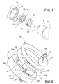
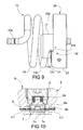
- stop means 30 are provided which are suitable to stop the first contact element 11 at the second contact element 21 to achieve the coupling between first and second parts of connector 10, 20, as shown in Fig. 9 .
- the resilient support structure 13 of the first part of the connector 10 biases the first contact element 11 in the axial direction against the abutment ring 23 and in the circumferential direction against the stop means 30.
- the means 30 include a protruding formation 31 provided on the abutment ring 23, which axially protrudes from the distal annular surface 23a of the abutment ring 23.
- a protruding formation is suitable to be engaged by a notch 17a which is shaped in a manner corresponding thereto and provided on the box-like body 17 within which the first contact element 11 is accommodated.
- the projecting formation 31 and the notch 17a have respective undercut surfaces 31b, 17b by means of which they are intended to engage each other.
- the first contact element 11 starts to engage the distal annular surface 23a of the abutment ring 23.
- the contact element 11 and the intermediate housing 19 thereof are pushed inwardly of the box-like body 17, against the action of the pack of Belleville washers 19a and of the resilient element 19b.
- the box-like body 17 abuts against the protruding formation 31 of the abutment ring 23, thereby preventing a further relative rotation of the box-like body 17 relative to the abutment ring 23.
- the first contact element 11 supported by the box-like body 17 is aligned with the respective contact element 21 supported by the abutment ring 23, thereby resulting in the closure of the electrical contact, and then the coupling between first and second parts of connector 10, 20.
- the sliding movement between the first contact element 11 and the abutment ring 23, which occurs in the final screwing step until the stop of the box-like body 17 against the protruding formation 31 causes a friction of the distal surfaces of the contact elements 11 and 21 which removes any dirt that may be present thereon.
- the further screwing between the drill pipes after the stop of the box-like body 17 against the protruding formation 31 has the effect of increasing the elastic load on the resilient support structure 13 until the completion of the fitting between the pipes.
- the undercut surfaces 17b and 31b of the box-like body 17 and of the protruding formation 31 of the abutment ring 23 act as an inclined plane that contribute along with the resilient force of the resilient support structure 13 of the first connector part 10 to hold the box-like body 17, and accordingly the contact element 11 against the abutment ring 23, and then against the second contact element 21.
- the resilient support structure 13 which has the beneficial effect of increasing the elastic force that biases the first contact element 11 in the axial direction against the abutment ring 23, and in the circumferential direction against the protruding formation 31 of the abutment ring 23.
- the resilient support structure 13 also supports the crushing increase which is due to the rimpedement between the pipe end elements.
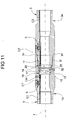
- Fig. 11 shows a variant embodiment in which the first part of the connector 10 comprises a resilient support structure 13 having the form of a right-handed coil spring, unlike the embodiment previously described, in which the spring was left-handed. This is to adapt the electrical connector according to the invention to a different way of screwing. Since the elements of the variant embodiment in Fig. 11 correspond to those of the previous embodiment, they have been designated with the same numerical references, and will not be further described herein.
- Fig. 12 shows the first connector part according to a variant embodiment in which the first connector part 10 includes a resilient support structure 13 having a tubular shape.
- This resilient support structure 13 includes a coil spring extending co-axially with the fitting axis y, and having a hollow section body, which spring is similar in structure and function to the coil springs described above.
- a coating 13c of elastomeric material is also a part of the structure 13 of the same variant embodiment, which coating is arranged to cover the space between the coils of the spring in order to provide the continuity of the structure 13.
- This variant embodiment provides a better sealing than the implementations without an elastomeric coating. Since the elements of the variant embodiment of Fig. 12 , except for the coating of elastomeric material, correspond to those of previous embodiments, they have been designated with the same numerical references, and will not be further described herein.
- first and second connector parts can be supported, more generally, by first and seconds supports, respectively, which can be assembled to one another by screw- or bayonet- fitting. It is essential that in the fitting movement between these supports a translational movement in the direction of the fitting axis (which in the above-described example coincides with the extension axis y of the pipes 1 and 3) and a rotational movement around the fitting axis are combined.
Landscapes
- Details Of Connecting Devices For Male And Female Coupling (AREA)
- Connector Housings Or Holding Contact Members (AREA)
- Coupling Device And Connection With Printed Circuit (AREA)
- Connection Of Batteries Or Terminals (AREA)
- Sealing Battery Cases Or Jackets (AREA)
Applications Claiming Priority (1)
| Application Number | Priority Date | Filing Date | Title |
|---|---|---|---|
| ITTO2010A000452A IT1400540B1 (it) | 2010-05-28 | 2010-05-28 | Connettore elettrico, in particolare per una batteria di trivellazione. |
Publications (2)
| Publication Number | Publication Date |
|---|---|
| EP2390965A1 EP2390965A1 (en) | 2011-11-30 |
| EP2390965B1 true EP2390965B1 (en) | 2014-09-24 |
Family
ID=43385668
Family Applications (1)
| Application Number | Title | Priority Date | Filing Date |
|---|---|---|---|
| EP11167574.0A Active EP2390965B1 (en) | 2010-05-28 | 2011-05-26 | An electrical connector, particularly for a drill string |
Country Status (13)
| Country | Link |
|---|---|
| US (1) | US8622760B2 (it) |
| EP (1) | EP2390965B1 (it) |
| JP (1) | JP5960392B2 (it) |
| CN (1) | CN102290672B (it) |
| AR (1) | AR081417A1 (it) |
| AU (1) | AU2011202451B2 (it) |
| BR (1) | BRPI1102488A2 (it) |
| CA (1) | CA2741150A1 (it) |
| ES (1) | ES2526769T3 (it) |
| IT (1) | IT1400540B1 (it) |
| MX (1) | MX2011005448A (it) |
| RU (1) | RU2556582C2 (it) |
| SG (1) | SG176411A1 (it) |
Families Citing this family (9)
| Publication number | Priority date | Publication date | Assignee | Title |
|---|---|---|---|---|
| ITTO20120019A1 (it) * | 2012-01-12 | 2013-07-13 | Pegasus S R L | Connettore per elementi tubolari |
| JP6780513B2 (ja) * | 2017-01-18 | 2020-11-04 | 株式会社オートネットワーク技術研究所 | 端子モジュール |
| RU2669969C1 (ru) * | 2018-01-11 | 2018-10-17 | Общество с ограниченной ответственностью "Пермская компания нефтяного машиностроения" | Способ монтажа токоподвода к электробуру при бурении скважины |
| CN110212369A (zh) * | 2019-06-06 | 2019-09-06 | 中航光电科技股份有限公司 | 插头连接器及连接器组件 |
| CN110932019B (zh) * | 2019-12-05 | 2024-11-01 | 中国电建集团河北工程有限公司 | 电力电缆接头 |
| CN115799930A (zh) * | 2021-09-10 | 2023-03-14 | 航天科工惯性技术有限公司 | 一种信号转接器 |
| EP4423880A4 (en) * | 2021-10-28 | 2025-09-17 | Services Petroliers Schlumberger | TERMINAL ASSEMBLY FOR ENCAPSULATED STATOR |
| US11980007B2 (en) * | 2021-12-21 | 2024-05-07 | Baidu Usa Llc | Cooling distribution unit for electronic racks |
| CN115621634B (zh) * | 2022-09-25 | 2025-05-06 | 山东北方光学电子有限公司 | 用于可佩戴光学仪器的电池盒装置和使用方法 |
Family Cites Families (16)
| Publication number | Priority date | Publication date | Assignee | Title |
|---|---|---|---|---|
| US3518609A (en) * | 1968-10-28 | 1970-06-30 | Shell Oil Co | Telemetry drill pipe with ring-control electrode means |
| US3879097A (en) * | 1974-01-25 | 1975-04-22 | Continental Oil Co | Electrical connectors for telemetering drill strings |
| US4286834A (en) * | 1979-11-13 | 1981-09-01 | International Telephone And Telegraph Corporation | Interconnection system |
| SU985265A1 (ru) * | 1981-01-07 | 1982-12-30 | Всесоюзный научно-исследовательский институт разработки и эксплуатации нефтепромысловых труб | Телеметрическа колонна бурильных труб |
| FR2578950B1 (fr) * | 1985-03-18 | 1988-01-15 | Socapex | Connecteur fluidique miniature |
| JPH0453232U (it) * | 1990-09-10 | 1992-05-07 | ||
| US5713765A (en) * | 1996-04-23 | 1998-02-03 | Nugent; Steven F. | High-current audio connector |
| US6402524B2 (en) * | 1997-10-14 | 2002-06-11 | Tracto-Technik Paul Schimdt Spezialmaschinen | Data transfer system |
| US6655464B2 (en) * | 1999-05-24 | 2003-12-02 | Merlin Technology Inc | Auto-extending/retracting electrically isolated conductors in a segmented drill string |
| US6845822B2 (en) * | 1999-05-24 | 2005-01-25 | Merlin Technology, Inc | Auto-extending/retracting electrically isolated conductors in a segmented drill string |
| US6641434B2 (en) * | 2001-06-14 | 2003-11-04 | Schlumberger Technology Corporation | Wired pipe joint with current-loop inductive couplers |
| US6844498B2 (en) * | 2003-01-31 | 2005-01-18 | Novatek Engineering Inc. | Data transmission system for a downhole component |
| US6929493B2 (en) * | 2003-05-06 | 2005-08-16 | Intelliserv, Inc. | Electrical contact for downhole drilling networks |
| EP1484471A3 (en) * | 2003-06-03 | 2004-12-15 | Intelliserv Inc | Improved transmission element for downhole drilling components |
| US7201240B2 (en) * | 2004-07-27 | 2007-04-10 | Intelliserv, Inc. | Biased insert for installing data transmission components in downhole drilling pipe |
| AT508272B1 (de) * | 2009-06-08 | 2011-01-15 | Advanced Drilling Solutions Gmbh | Vorrichtung zum verbinden von elektrischen leitungen |
-
2010
- 2010-05-28 IT ITTO2010A000452A patent/IT1400540B1/it active
-
2011
- 2011-05-23 US US13/113,544 patent/US8622760B2/en active Active
- 2011-05-23 BR BRPI1102488-7A patent/BRPI1102488A2/pt not_active IP Right Cessation
- 2011-05-23 MX MX2011005448A patent/MX2011005448A/es active IP Right Grant
- 2011-05-24 AR ARP110101774A patent/AR081417A1/es not_active Application Discontinuation
- 2011-05-25 AU AU2011202451A patent/AU2011202451B2/en not_active Ceased
- 2011-05-25 CA CA2741150A patent/CA2741150A1/en not_active Abandoned
- 2011-05-25 JP JP2011116857A patent/JP5960392B2/ja not_active Expired - Fee Related
- 2011-05-26 EP EP11167574.0A patent/EP2390965B1/en active Active
- 2011-05-26 RU RU2011121368/03A patent/RU2556582C2/ru not_active IP Right Cessation
- 2011-05-26 ES ES11167574.0T patent/ES2526769T3/es active Active
- 2011-05-27 CN CN201110140304.4A patent/CN102290672B/zh not_active Expired - Fee Related
- 2011-05-27 SG SG2011038858A patent/SG176411A1/en unknown
Also Published As
| Publication number | Publication date |
|---|---|
| JP2011249333A (ja) | 2011-12-08 |
| JP5960392B2 (ja) | 2016-08-02 |
| US8622760B2 (en) | 2014-01-07 |
| CA2741150A1 (en) | 2011-11-28 |
| RU2556582C2 (ru) | 2015-07-10 |
| SG176411A1 (en) | 2011-12-29 |
| IT1400540B1 (it) | 2013-06-11 |
| MX2011005448A (es) | 2011-11-28 |
| ES2526769T3 (es) | 2015-01-15 |
| CN102290672B (zh) | 2015-06-17 |
| AU2011202451B2 (en) | 2015-01-29 |
| CN102290672A (zh) | 2011-12-21 |
| AR081417A1 (es) | 2012-08-29 |
| US20110294343A1 (en) | 2011-12-01 |
| ITTO20100452A1 (it) | 2011-11-29 |
| RU2011121368A (ru) | 2012-12-10 |
| AU2011202451A1 (en) | 2011-12-15 |
| EP2390965A1 (en) | 2011-11-30 |
| BRPI1102488A2 (pt) | 2013-12-17 |
Similar Documents
| Publication | Publication Date | Title |
|---|---|---|
| EP2390965B1 (en) | An electrical connector, particularly for a drill string | |
| EP2964879B1 (en) | Electrical penetrator assembly | |
| US7997929B2 (en) | Phone plug connector device | |
| CN109462065B (zh) | 一种适用于极端严酷环境的连接器线缆组件 | |
| US20130012063A1 (en) | Cable connector | |
| KR102798389B1 (ko) | 지상개폐기용 접속재 | |
| CN102403583A (zh) | 具有螺纹锁定夹头和螺母的电缆连接器 | |
| MX2007000545A (es) | Conector de compresion para cable coaxial. | |
| CN103026554A (zh) | 电连接器和包括该电连接器的电源设备 | |
| TWM456602U (zh) | 大電流電連接器 | |
| HK1165621A (en) | An electrical connector, particularly for a drill string | |
| GB2208191A (en) | Sealed electrical connector | |
| CN209526272U (zh) | 连接器组件用连接螺帽组件 | |
| CN209150338U (zh) | 适用于极端严酷环境的连接器线缆组件 | |
| CN211428424U (zh) | 一种井下专用电缆连接装置 | |
| KR102640069B1 (ko) | 지상개폐기용 스터드 볼트 구조체 | |
| US20110221186A1 (en) | Connection mechanisms | |
| CN116613572A (zh) | 三同轴高压电缆连接器 | |
| JP2002135961A (ja) | プレモールド絶縁体押圧装置 |
Legal Events
| Date | Code | Title | Description |
|---|---|---|---|
| AK | Designated contracting states |
Kind code of ref document: A1 Designated state(s): AL AT BE BG CH CY CZ DE DK EE ES FI FR GB GR HR HU IE IS IT LI LT LU LV MC MK MT NL NO PL PT RO RS SE SI SK SM TR |
|
| AX | Request for extension of the european patent |
Extension state: BA ME |
|
| PUAI | Public reference made under article 153(3) epc to a published international application that has entered the european phase |
Free format text: ORIGINAL CODE: 0009012 |
|
| 17P | Request for examination filed |
Effective date: 20120313 |
|
| 17Q | First examination report despatched |
Effective date: 20131011 |
|
| GRAP | Despatch of communication of intention to grant a patent |
Free format text: ORIGINAL CODE: EPIDOSNIGR1 |
|
| RIC1 | Information provided on ipc code assigned before grant |
Ipc: E21B 17/20 20060101ALN20140409BHEP Ipc: H01R 13/533 20060101AFI20140409BHEP |
|
| INTG | Intention to grant announced |
Effective date: 20140425 |
|
| GRAS | Grant fee paid |
Free format text: ORIGINAL CODE: EPIDOSNIGR3 |
|
| GRAA | (expected) grant |
Free format text: ORIGINAL CODE: 0009210 |
|
| AK | Designated contracting states |
Kind code of ref document: B1 Designated state(s): AL AT BE BG CH CY CZ DE DK EE ES FI FR GB GR HR HU IE IS IT LI LT LU LV MC MK MT NL NO PL PT RO RS SE SI SK SM TR |
|
| AX | Request for extension of the european patent |
Extension state: BA ME |
|
| REG | Reference to a national code |
Ref country code: GB Ref legal event code: FG4D |
|
| REG | Reference to a national code |
Ref country code: CH Ref legal event code: EP |
|
| REG | Reference to a national code |
Ref country code: AT Ref legal event code: REF Ref document number: 688970 Country of ref document: AT Kind code of ref document: T Effective date: 20141015 |
|
| REG | Reference to a national code |
Ref country code: IE Ref legal event code: FG4D |
|
| REG | Reference to a national code |
Ref country code: DE Ref legal event code: R096 Ref document number: 602011010057 Country of ref document: DE Effective date: 20141106 |
|
| REG | Reference to a national code |
Ref country code: ES Ref legal event code: FG2A Ref document number: 2526769 Country of ref document: ES Kind code of ref document: T3 Effective date: 20150115 |
|
| REG | Reference to a national code |
Ref country code: NL Ref legal event code: T3 |
|
| PG25 | Lapsed in a contracting state [announced via postgrant information from national office to epo] |
Ref country code: GR Free format text: LAPSE BECAUSE OF FAILURE TO SUBMIT A TRANSLATION OF THE DESCRIPTION OR TO PAY THE FEE WITHIN THE PRESCRIBED TIME-LIMIT Effective date: 20141225 Ref country code: FI Free format text: LAPSE BECAUSE OF FAILURE TO SUBMIT A TRANSLATION OF THE DESCRIPTION OR TO PAY THE FEE WITHIN THE PRESCRIBED TIME-LIMIT Effective date: 20140924 Ref country code: LT Free format text: LAPSE BECAUSE OF FAILURE TO SUBMIT A TRANSLATION OF THE DESCRIPTION OR TO PAY THE FEE WITHIN THE PRESCRIBED TIME-LIMIT Effective date: 20140924 Ref country code: SE Free format text: LAPSE BECAUSE OF FAILURE TO SUBMIT A TRANSLATION OF THE DESCRIPTION OR TO PAY THE FEE WITHIN THE PRESCRIBED TIME-LIMIT Effective date: 20140924 |
|
| REG | Reference to a national code |
Ref country code: NO Ref legal event code: T2 Effective date: 20140924 |
|
| REG | Reference to a national code |
Ref country code: LT Ref legal event code: MG4D |
|
| PG25 | Lapsed in a contracting state [announced via postgrant information from national office to epo] |
Ref country code: LV Free format text: LAPSE BECAUSE OF FAILURE TO SUBMIT A TRANSLATION OF THE DESCRIPTION OR TO PAY THE FEE WITHIN THE PRESCRIBED TIME-LIMIT Effective date: 20140924 Ref country code: RS Free format text: LAPSE BECAUSE OF FAILURE TO SUBMIT A TRANSLATION OF THE DESCRIPTION OR TO PAY THE FEE WITHIN THE PRESCRIBED TIME-LIMIT Effective date: 20140924 Ref country code: HR Free format text: LAPSE BECAUSE OF FAILURE TO SUBMIT A TRANSLATION OF THE DESCRIPTION OR TO PAY THE FEE WITHIN THE PRESCRIBED TIME-LIMIT Effective date: 20140924 Ref country code: CY Free format text: LAPSE BECAUSE OF FAILURE TO SUBMIT A TRANSLATION OF THE DESCRIPTION OR TO PAY THE FEE WITHIN THE PRESCRIBED TIME-LIMIT Effective date: 20140924 |
|
| REG | Reference to a national code |
Ref country code: AT Ref legal event code: MK05 Ref document number: 688970 Country of ref document: AT Kind code of ref document: T Effective date: 20140924 |
|
| PG25 | Lapsed in a contracting state [announced via postgrant information from national office to epo] |
Ref country code: IS Free format text: LAPSE BECAUSE OF FAILURE TO SUBMIT A TRANSLATION OF THE DESCRIPTION OR TO PAY THE FEE WITHIN THE PRESCRIBED TIME-LIMIT Effective date: 20150124 Ref country code: SK Free format text: LAPSE BECAUSE OF FAILURE TO SUBMIT A TRANSLATION OF THE DESCRIPTION OR TO PAY THE FEE WITHIN THE PRESCRIBED TIME-LIMIT Effective date: 20140924 Ref country code: EE Free format text: LAPSE BECAUSE OF FAILURE TO SUBMIT A TRANSLATION OF THE DESCRIPTION OR TO PAY THE FEE WITHIN THE PRESCRIBED TIME-LIMIT Effective date: 20140924 Ref country code: RO Free format text: LAPSE BECAUSE OF FAILURE TO SUBMIT A TRANSLATION OF THE DESCRIPTION OR TO PAY THE FEE WITHIN THE PRESCRIBED TIME-LIMIT Effective date: 20140924 Ref country code: CZ Free format text: LAPSE BECAUSE OF FAILURE TO SUBMIT A TRANSLATION OF THE DESCRIPTION OR TO PAY THE FEE WITHIN THE PRESCRIBED TIME-LIMIT Effective date: 20140924 Ref country code: PT Free format text: LAPSE BECAUSE OF FAILURE TO SUBMIT A TRANSLATION OF THE DESCRIPTION OR TO PAY THE FEE WITHIN THE PRESCRIBED TIME-LIMIT Effective date: 20150126 |
|
| PG25 | Lapsed in a contracting state [announced via postgrant information from national office to epo] |
Ref country code: AT Free format text: LAPSE BECAUSE OF FAILURE TO SUBMIT A TRANSLATION OF THE DESCRIPTION OR TO PAY THE FEE WITHIN THE PRESCRIBED TIME-LIMIT Effective date: 20140924 Ref country code: PL Free format text: LAPSE BECAUSE OF FAILURE TO SUBMIT A TRANSLATION OF THE DESCRIPTION OR TO PAY THE FEE WITHIN THE PRESCRIBED TIME-LIMIT Effective date: 20140924 |
|
| REG | Reference to a national code |
Ref country code: FR Ref legal event code: PLFP Year of fee payment: 5 |
|
| REG | Reference to a national code |
Ref country code: DE Ref legal event code: R097 Ref document number: 602011010057 Country of ref document: DE |
|
| PG25 | Lapsed in a contracting state [announced via postgrant information from national office to epo] |
Ref country code: DK Free format text: LAPSE BECAUSE OF FAILURE TO SUBMIT A TRANSLATION OF THE DESCRIPTION OR TO PAY THE FEE WITHIN THE PRESCRIBED TIME-LIMIT Effective date: 20140924 |
|
| PGFP | Annual fee paid to national office [announced via postgrant information from national office to epo] |
Ref country code: NO Payment date: 20150515 Year of fee payment: 5 Ref country code: ES Payment date: 20150522 Year of fee payment: 5 Ref country code: GB Payment date: 20150521 Year of fee payment: 5 |
|
| PLBE | No opposition filed within time limit |
Free format text: ORIGINAL CODE: 0009261 |
|
| STAA | Information on the status of an ep patent application or granted ep patent |
Free format text: STATUS: NO OPPOSITION FILED WITHIN TIME LIMIT |
|
| PG25 | Lapsed in a contracting state [announced via postgrant information from national office to epo] |
Ref country code: IT Free format text: LAPSE BECAUSE OF FAILURE TO SUBMIT A TRANSLATION OF THE DESCRIPTION OR TO PAY THE FEE WITHIN THE PRESCRIBED TIME-LIMIT Effective date: 20140924 |
|
| PGFP | Annual fee paid to national office [announced via postgrant information from national office to epo] |
Ref country code: NL Payment date: 20150526 Year of fee payment: 5 Ref country code: FR Payment date: 20150601 Year of fee payment: 5 |
|
| 26N | No opposition filed |
Effective date: 20150625 |
|
| PGFP | Annual fee paid to national office [announced via postgrant information from national office to epo] |
Ref country code: DE Payment date: 20150730 Year of fee payment: 5 |
|
| REG | Reference to a national code |
Ref country code: CH Ref legal event code: PL |
|
| PG25 | Lapsed in a contracting state [announced via postgrant information from national office to epo] |
Ref country code: MC Free format text: LAPSE BECAUSE OF FAILURE TO SUBMIT A TRANSLATION OF THE DESCRIPTION OR TO PAY THE FEE WITHIN THE PRESCRIBED TIME-LIMIT Effective date: 20140924 Ref country code: CH Free format text: LAPSE BECAUSE OF NON-PAYMENT OF DUE FEES Effective date: 20150531 Ref country code: LU Free format text: LAPSE BECAUSE OF FAILURE TO SUBMIT A TRANSLATION OF THE DESCRIPTION OR TO PAY THE FEE WITHIN THE PRESCRIBED TIME-LIMIT Effective date: 20150526 Ref country code: LI Free format text: LAPSE BECAUSE OF NON-PAYMENT OF DUE FEES Effective date: 20150531 |
|
| REG | Reference to a national code |
Ref country code: IE Ref legal event code: MM4A |
|
| PG25 | Lapsed in a contracting state [announced via postgrant information from national office to epo] |
Ref country code: SI Free format text: LAPSE BECAUSE OF FAILURE TO SUBMIT A TRANSLATION OF THE DESCRIPTION OR TO PAY THE FEE WITHIN THE PRESCRIBED TIME-LIMIT Effective date: 20140924 |
|
| PG25 | Lapsed in a contracting state [announced via postgrant information from national office to epo] |
Ref country code: IE Free format text: LAPSE BECAUSE OF NON-PAYMENT OF DUE FEES Effective date: 20150526 |
|
| REG | Reference to a national code |
Ref country code: DE Ref legal event code: R119 Ref document number: 602011010057 Country of ref document: DE |
|
| REG | Reference to a national code |
Ref country code: NO Ref legal event code: MMEP |
|
| PG25 | Lapsed in a contracting state [announced via postgrant information from national office to epo] |
Ref country code: MT Free format text: LAPSE BECAUSE OF FAILURE TO SUBMIT A TRANSLATION OF THE DESCRIPTION OR TO PAY THE FEE WITHIN THE PRESCRIBED TIME-LIMIT Effective date: 20140924 |
|
| REG | Reference to a national code |
Ref country code: NL Ref legal event code: MM Effective date: 20160601 |
|
| GBPC | Gb: european patent ceased through non-payment of renewal fee |
Effective date: 20160526 |
|
| PG25 | Lapsed in a contracting state [announced via postgrant information from national office to epo] |
Ref country code: NO Free format text: LAPSE BECAUSE OF NON-PAYMENT OF DUE FEES Effective date: 20160531 |
|
| PG25 | Lapsed in a contracting state [announced via postgrant information from national office to epo] |
Ref country code: NL Free format text: LAPSE BECAUSE OF NON-PAYMENT OF DUE FEES Effective date: 20160601 |
|
| REG | Reference to a national code |
Ref country code: FR Ref legal event code: ST Effective date: 20170131 |
|
| PG25 | Lapsed in a contracting state [announced via postgrant information from national office to epo] |
Ref country code: DE Free format text: LAPSE BECAUSE OF NON-PAYMENT OF DUE FEES Effective date: 20161201 Ref country code: FR Free format text: LAPSE BECAUSE OF NON-PAYMENT OF DUE FEES Effective date: 20160531 |
|
| PG25 | Lapsed in a contracting state [announced via postgrant information from national office to epo] |
Ref country code: BG Free format text: LAPSE BECAUSE OF FAILURE TO SUBMIT A TRANSLATION OF THE DESCRIPTION OR TO PAY THE FEE WITHIN THE PRESCRIBED TIME-LIMIT Effective date: 20140924 Ref country code: GB Free format text: LAPSE BECAUSE OF NON-PAYMENT OF DUE FEES Effective date: 20160526 Ref country code: SM Free format text: LAPSE BECAUSE OF FAILURE TO SUBMIT A TRANSLATION OF THE DESCRIPTION OR TO PAY THE FEE WITHIN THE PRESCRIBED TIME-LIMIT Effective date: 20140924 Ref country code: HU Free format text: LAPSE BECAUSE OF FAILURE TO SUBMIT A TRANSLATION OF THE DESCRIPTION OR TO PAY THE FEE WITHIN THE PRESCRIBED TIME-LIMIT; INVALID AB INITIO Effective date: 20110526 |
|
| PG25 | Lapsed in a contracting state [announced via postgrant information from national office to epo] |
Ref country code: TR Free format text: LAPSE BECAUSE OF FAILURE TO SUBMIT A TRANSLATION OF THE DESCRIPTION OR TO PAY THE FEE WITHIN THE PRESCRIBED TIME-LIMIT Effective date: 20140924 |
|
| PG25 | Lapsed in a contracting state [announced via postgrant information from national office to epo] |
Ref country code: BE Free format text: LAPSE BECAUSE OF FAILURE TO SUBMIT A TRANSLATION OF THE DESCRIPTION OR TO PAY THE FEE WITHIN THE PRESCRIBED TIME-LIMIT Effective date: 20140924 |
|
| PG25 | Lapsed in a contracting state [announced via postgrant information from national office to epo] |
Ref country code: ES Free format text: LAPSE BECAUSE OF NON-PAYMENT OF DUE FEES Effective date: 20160527 |
|
| REG | Reference to a national code |
Ref country code: ES Ref legal event code: FD2A Effective date: 20180625 |
|
| PG25 | Lapsed in a contracting state [announced via postgrant information from national office to epo] |
Ref country code: MK Free format text: LAPSE BECAUSE OF FAILURE TO SUBMIT A TRANSLATION OF THE DESCRIPTION OR TO PAY THE FEE WITHIN THE PRESCRIBED TIME-LIMIT Effective date: 20140924 |
|
| PG25 | Lapsed in a contracting state [announced via postgrant information from national office to epo] |
Ref country code: AL Free format text: LAPSE BECAUSE OF FAILURE TO SUBMIT A TRANSLATION OF THE DESCRIPTION OR TO PAY THE FEE WITHIN THE PRESCRIBED TIME-LIMIT Effective date: 20140924 |