EP2390975A2 - Dispositif de refroidissement pour une installation de commutation électrique - Google Patents
Dispositif de refroidissement pour une installation de commutation électrique Download PDFInfo
- Publication number
- EP2390975A2 EP2390975A2 EP11166868A EP11166868A EP2390975A2 EP 2390975 A2 EP2390975 A2 EP 2390975A2 EP 11166868 A EP11166868 A EP 11166868A EP 11166868 A EP11166868 A EP 11166868A EP 2390975 A2 EP2390975 A2 EP 2390975A2
- Authority
- EP
- European Patent Office
- Prior art keywords
- heat
- cooling device
- frame
- cooling
- plates
- Prior art date
- Legal status (The legal status is an assumption and is not a legal conclusion. Google has not performed a legal analysis and makes no representation as to the accuracy of the status listed.)
- Granted
Links
Images

Classifications
-
- H—ELECTRICITY
- H01—ELECTRIC ELEMENTS
- H01H—ELECTRIC SWITCHES; RELAYS; SELECTORS; EMERGENCY PROTECTIVE DEVICES
- H01H9/00—Details of switching devices, not covered by groups H01H1/00 - H01H7/00
- H01H9/52—Cooling of switch parts
-
- H—ELECTRICITY
- H01—ELECTRIC ELEMENTS
- H01H—ELECTRIC SWITCHES; RELAYS; SELECTORS; EMERGENCY PROTECTIVE DEVICES
- H01H1/00—Contacts
- H01H1/62—Heating or cooling of contacts
-
- H—ELECTRICITY
- H01—ELECTRIC ELEMENTS
- H01H—ELECTRIC SWITCHES; RELAYS; SELECTORS; EMERGENCY PROTECTIVE DEVICES
- H01H9/00—Details of switching devices, not covered by groups H01H1/00 - H01H7/00
- H01H9/52—Cooling of switch parts
- H01H2009/523—Cooling of switch parts by using heat pipes
-
- H—ELECTRICITY
- H01—ELECTRIC ELEMENTS
- H01H—ELECTRIC SWITCHES; RELAYS; SELECTORS; EMERGENCY PROTECTIVE DEVICES
- H01H9/00—Details of switching devices, not covered by groups H01H1/00 - H01H7/00
- H01H9/52—Cooling of switch parts
- H01H2009/526—Cooling of switch parts of the high voltage switches
-
- H—ELECTRICITY
- H02—GENERATION; CONVERSION OR DISTRIBUTION OF ELECTRIC POWER
- H02B—BOARDS, SUBSTATIONS OR SWITCHING ARRANGEMENTS FOR THE SUPPLY OR DISTRIBUTION OF ELECTRIC POWER
- H02B11/00—Switchgear having carriage withdrawable for isolation
- H02B11/02—Details
- H02B11/04—Isolating-contacts, e.g. mountings or shieldings
Definitions
- the invention relates to a cooling device for an electrical switchgear, in particular in the field of medium or high voltage engineering.
- a vacuum circuit breaker is known in which a contact piece is provided within the vacuum switch with a heat pipe. With the help of the heat pipe so the heat generated at the contact piece is guided out of the vacuum switch.
- a heat pipe In a heat pipe is a working fluid in an evacuated, hermetically sealed metal tube.
- the working medium evaporates and transports the heat to the cold end of the heat pipe.
- the working fluid condenses and releases the heat to the heat pipe and its surroundings.
- the condensed working fluid then flows back to the hot end of the heat pipe, for example, by means of gravitational force or capillary action in the heat pipe.
- the object of the invention is to improve the known cooling device.
- the invention solves this problem by a cooling device for an electrical switchgear, which is provided with a frame which limits a region in which a plurality of cooling plates are arranged, and which is further provided with at least one heat pipe, on the one hand with a heat-emitting portion the cooling device and on the other hand coupled to the cooling plates.
- the heat is thus transported from the heat-emitting portion of the hot end of the heat pipe to its cold end and thus to the cooling plates and discharged through this to the environment.
- the heat-emitting portion may be connected to a heat-emitting component of the switchgear, such as an electrical pole or an electrical conductor.
- the cooling device according to the invention can dissipate a high amount of heat and at the same time has a very compact and lightweight construction.
- the reduction to the frame, the cooling plates and the heat pipe also creates a very simple design and thus easy and inexpensive to produce cooling device.
- the arrangement of the cooling plates within the limited area of the frame has the advantage that the cooling plates are electrically shielded by means of the frame and also mechanically protected.
- the inventive Cooling device thus has a high dielectric strength even when used in the field of medium and high voltage technology.
- the heat pipe according to the invention is not used for dissipating heat, for example from a contact piece of a vacuum switch, but for dissipating the heat of a generally heat-emitting component of the switchgear to the cooling plates, from which the heat is then released to the environment.
- the portion of the cooling device is connected to at least one plate of a circuit breaker. This makes it possible in a simple manner, dissipate the heat usually generated at a circuit breaker via the cooling device according to the invention.
- a further, particularly advantageous embodiment of the invention is that the frame, the sub-area, the cooling plates, the heat pipe and the heat-emitting component of the switchgear are formed as an integrated component. This leads to a particularly compact design for the cooling device according to the invention.
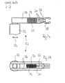
- FIGS. 1a, 1b show a schematic perspective view and a plan view of a first embodiment of a cooling device according to the invention
- FIGS. 2a, 2b show a schematic side and top view of a second embodiment of a cooling device according to the invention.
- FIGS. 1a, 1b a cooling device 10 is shown, which can be used for use in air or gas-insulated electrical switchgear of medium or high voltage engineering.
- FIGS. 1a, 1b for example, a pole 13 of a circuit breaker.
- This pole 13 has, by way of example, two disk-like plates 14, which are arranged at a distance and approximately parallel to one another.
- the other pole of the circuit breaker is in the FIG. 1 not shown.
- This other pole may, for example, be a swiveling switch blade which can either be pivoted between the two plates 14 or separated from the two plates 14.
- FIGS. 1a, 1b is shown the disconnected state in which the circuit breaker is thus in its current interrupting state.
- the circuit breaker may be connected to a pole of a vacuum switch.
- This vacuum switch can in a manner not shown for Example be arranged below the cooling device 10, ie in the perspective view of FIG. 1b in particular, approximately below the holes 16 of the cooling device 10 which are still to be explained.
- the two plates 14 of the circuit breaker are connected to each other by means of a plate-like portion 15 of the cooling device 10.
- the portion 15 starts from the distance between the two plates 14 and expands from there in the direction of the still to be explained frame 18 to a greater distance.
- the portion 15 has a plurality of holes 16 through which the circuit breaker 13 may be attached in any manner not shown in detail, for example, to the vacuum switch.
- the portion 15 is a current-carrying conductor element in the current path from the vacuum switch to the circuit breaker.
- the plates 14 and the portion 15 are integrally formed in an exemplary manner and are made of an electrically and thermally conductive material. It is understood that this arrangement can also be designed in several parts.
- the free ends of the two legs of the frame 18 are approximately in the same plane as the plates 14 of the portion 15 from.
- the frame 18 is made of an electrically conductive material and is exemplified integrally formed with the portion 15 and the plates 14. In that regard, it is in the embodiment of the FIGS. 1a, 1b around an integrated component. Alternatively it is possible that the frame 18, the portion 15 and the plates 14 are formed in several parts and each consist of an electrically conductive material.
- the cooling plates 19 are made of an electrically and thermally conductive material. Furthermore, the cooling plates 19 all have the same surface shape, are arranged at a distance and approximately parallel to each other and approximately planar.
- the cooling plates 19 are aligned approximately parallel to the connecting web of the U-shaped frame 18. If one assigns a length to this connecting web, the surface shape of the cooling plates 19 has approximately the same length. Assigning the frame 18 to a width extending approximately transversely to the direction of the connecting web, the surface shape of the cooling plates 19 has approximately the same width.
- cooling plates 19 may also be designed differently. It is also possible that the cooling plates 19 are not flat, but have a shape, for example, provided with bulges or openings. Finally, it is also possible that the cooling plates 19 are replaced by a plurality of cooling pins, for example, projecting from a flat base part, which is located within the area enclosed by the U-shaped frame 18 area.
- the frame 18 is used for electrical shielding of the cooling plates 19.
- the frame 18 thus avoids that small radii or other edges of the cooling plates 19 lead to electrical discharges.
- the frame 18 is a protection of the cooling plates 19 against mechanical damage.
- cooling plates 19 In the cooling plates 19 are openings through which two heat pipes 21 are inserted through the present embodiment.
- the heat pipes 21 are connected to the cooling plates 19, for example, soldered or pressed or expanded, that the best possible thermal transition is present.
- the heat pipes 21 are straight and extend approximately transversely to the orientation of the cooling plates 19th
- openings are also included, in which the two heat pipes 21 are inserted into and soldered, for example.
- the heat pipes 21 and the associated openings in the subregion 15 are adapted to one another in such a way that a form or interference fit and thus the best possible thermal transition is present.
- the heat pipes 21 are thus connected on one side to the portion 15, but otherwise have no connection to the frame 18.
- the portion 15 is formed in two parts, that the heat pipes 21 placed in between and then can be pressed by screwing.
- the two heat pipes 21 have a spacing and are aligned approximately parallel to one another. It is understood that even just one heat pipe 21 or more than two Heat pipes 21 may be present.
- the heat pipes 21 are made of an electrically conductive material.
- the heat pipes 21 are each a so-called "heat pipe".
- a working medium such as water
- Each of the heat pipes 21 has a heat transfer surface for a heat source and a heat transfer surface for a heat sink. If heating by the heat source takes place in the heat transfer surface for the heat source, the working medium begins to evaporate. As a result, the pressure in the heat pipe 21 is increased, which leads to a pressure gradient within the heat pipe 21. The resulting vapor thus flows in the direction of the heat transfer surface for the heat sink, where it condenses because of the lower temperature there.
- the heat previously emitted by the heat source and absorbed by the working medium is released to the heat transfer surface for the heat sink and thus to the heat pipe 21.
- the now liquid working medium returns by capillary action or capillary action of the respective heat pipe 21 back to the heat transfer surface for the heat source.
- the portion 15, the heat source and the cooling plates 19, the heat sink Furthermore, put in the portion 15 free ends of the heat pipes 21, the heat transfer surfaces for the heat source and through the cooling plates 19 inserted through the free ends of the heat pipes 21, the heat transfer surfaces for the heat sink.
- the pole 13 of the circuit breaker and the pole of the vacuum switch each represent a so-called hot spot.
- these two components are connected to one another via the partial region 15.
- the portion 15 forms a heat-emitting component.
- Heat that forms during operation of the switchgear for example, in the region of the two plates 14 of the circuit breaker, will thus deliver over the portion 15 to the heat-receiving end of the two heat pipes 21.
- the heat with the aid of the working medium in the direction of the other, heat-emitting end of the two heat pipes 21 is transported. There, the heat is released to the cooling plates 19.
- the heat is distributed on the surfaces of the cooling plates 19 and is discharged from there to the environment.
- the condensed working medium returns to the part 15 associated free ends of the heat pipes 21 back.
- the cooling device 10 is in the embodiment of the FIGS. 1a, 1b in particular from the plates 14, the portion 15, the frame 18, the cooling plates 19 and the heat pipes 21 together. These components are all electrically at the same potential, always at the potential of the medium or high voltage of the switchgear. Thus, no current flows through the frame 18, the cooling plates 19 or the heat pipes 21. The current is only passed over the plates 14 and the portion 15 of the circuit breaker to the vacuum switch and only the heat there is dissipated via the cooling device 10.
- the number, the surface shape and the distance of the cooling plates 19 and the number, the length and the distance of the heat pipes 21 are variable. These parameters can be changed or selected accordingly for the particular switchgear in dependence on the heat to be dissipated.
- the in the FIGS. 1a, 1b illustrated cooling device 10 may optionally be retrofitted in an existing switchgear. It is also possible that several such cooling devices 10 are arranged at different locations within a switchgear.
- the described cooling device 10 can also be used independently of the mentioned vacuum switch, ie only in connection with the pole 13 of said circuit breaker.
- the cooling device 10 is used in this case for cooling the pole 13.
- the cooling device 10 can be fastened by means of the holes 16 within the switchgear so that automatically arranged with the assembly of the plate 14 formed by the pole 13 correctly within the switchgear is.
- the cooling device of FIGS. 1a, 1b is also used only for cooling an electrical conductor, which leads, for example, to the pole 13 formed by the plates 14.
- the cooling device 10 is thus used largely independently of the said disconnecting switch, as well as independently of the mentioned vacuum switch.
- FIGS. 2a, 2b a cooling device 50 is shown, which largely in terms of their basic structure of the cooling device 10 of FIGS. 1a, 1b equivalent. Similar features of the cooling device 50 are therefore in the FIGS. 2a, 2b denoted by the same reference numerals as in the FIGS. 1a, 1b , With regard to these similar characteristics, reference is made to the Explanatory Notes to the FIGS. 1a, 1b directed. Below are essentially those features of the cooling device 50 of FIGS. 2a, 2b described by the cooling device 10 of the FIGS. 1a, 1b differ.
- the cooling device 50 is integrated into a disconnect contact 52 of a mobile circuit breaker carriage of an air-insulated switchgear.
- the isolating contact 52 is mechanically connected via a column 53 in a manner not shown to the circuit breaker car and can therefore be moved back and forth together with the circuit breaker carriage in the direction indicated by the double arrow 54 directions.
- the isolating contact 52 is constructed of two strips 56, which are arranged side by side in parallel. At their one free end, the strips 56 are connected in unspecified manner with the column 53 and at its other free end, the strips 56 are connected to each other via a connecting part 57.
- the connecting part 57 forms in comparison with the FIGS. 1a, 1b the local subarea 15.
- jaws 58 are held, which project in the direction of the strips 56, and via which an electrical connection with or a separation of a other, not shown electrical conductor of the switchgear is vorappelbar.
- the cooling device 50 is arranged between the two strips 56.
- the cooling device has a plurality of cooling plates 19 and two heat pipes 21, which are thermally coupled to the connecting part 57.
- the two strips 56 of Figures 3a, 3b form a frame for the cooling plates 19.
- the heat pipes 21 are thus held on one side in the connecting part 57, but have no other connection to the strips 56 on.
- the jaws 58 represent a hot spot of the isolating contact 52.
- the heat present there is transmitted via the connecting part 57 and the heat pipes 21 to the cooling plates 19 and discharged there to the environment.
Landscapes
- Cooling Or The Like Of Electrical Apparatus (AREA)
- Cooling Or The Like Of Semiconductors Or Solid State Devices (AREA)
- Patch Boards (AREA)
Applications Claiming Priority (1)
| Application Number | Priority Date | Filing Date | Title |
|---|---|---|---|
| DE102010022087A DE102010022087A1 (de) | 2010-05-31 | 2010-05-31 | Kühlvorrichtung für eine elektrische Schaltanlage |
Publications (3)
| Publication Number | Publication Date |
|---|---|
| EP2390975A2 true EP2390975A2 (fr) | 2011-11-30 |
| EP2390975A3 EP2390975A3 (fr) | 2014-01-29 |
| EP2390975B1 EP2390975B1 (fr) | 2018-10-17 |
Family
ID=44117848
Family Applications (1)
| Application Number | Title | Priority Date | Filing Date |
|---|---|---|---|
| EP11166868.7A Active EP2390975B1 (fr) | 2010-05-31 | 2011-05-20 | Dispositif de refroidissement pour une installation de commutation électrique |
Country Status (2)
| Country | Link |
|---|---|
| EP (1) | EP2390975B1 (fr) |
| DE (1) | DE102010022087A1 (fr) |
Cited By (1)
| Publication number | Priority date | Publication date | Assignee | Title |
|---|---|---|---|---|
| CN111370247A (zh) * | 2020-03-18 | 2020-07-03 | 南通苏源恒炫电气有限公司 | 一种穿墙式触头座 |
Families Citing this family (1)
| Publication number | Priority date | Publication date | Assignee | Title |
|---|---|---|---|---|
| CN118231199A (zh) * | 2022-12-21 | 2024-06-21 | Abb瑞士股份有限公司 | 用于电气设备中的热管理的断路器和梅花触头 |
Citations (1)
| Publication number | Priority date | Publication date | Assignee | Title |
|---|---|---|---|---|
| US4005297A (en) | 1972-10-18 | 1977-01-25 | Westinghouse Electric Corporation | Vacuum-type circuit interrupters having heat-dissipating devices associated with the contact structures thereof |
Family Cites Families (7)
| Publication number | Priority date | Publication date | Assignee | Title |
|---|---|---|---|---|
| US3621108A (en) * | 1970-01-21 | 1971-11-16 | Westinghouse Electric Corp | Heat-conducting fins for bus bars and other electrical conductors |
| US3662137A (en) * | 1970-01-21 | 1972-05-09 | Westinghouse Electric Corp | Switchgear having heat pipes incorporated in the disconnecting structures and power conductors |
| JPS6472430A (en) * | 1987-09-14 | 1989-03-17 | Hitachi Ltd | Enclosed switchboard |
| US5753875A (en) * | 1996-10-15 | 1998-05-19 | Eaton Corporation | Heat sink for contact stems of a vacuum interrupter and a vacuum interrupter therewith |
| DE20121796U1 (de) * | 2001-12-21 | 2003-05-15 | Siemens AG, 80333 München | Polarmatur |
| JP2005166449A (ja) * | 2003-12-02 | 2005-06-23 | Mitsubishi Electric Corp | 真空開閉器 |
| DE102005011405B3 (de) * | 2005-03-03 | 2006-11-16 | Siemens Ag | Schaltgerät mit Wärmerohr |
-
2010
- 2010-05-31 DE DE102010022087A patent/DE102010022087A1/de not_active Withdrawn
-
2011
- 2011-05-20 EP EP11166868.7A patent/EP2390975B1/fr active Active
Patent Citations (1)
| Publication number | Priority date | Publication date | Assignee | Title |
|---|---|---|---|---|
| US4005297A (en) | 1972-10-18 | 1977-01-25 | Westinghouse Electric Corporation | Vacuum-type circuit interrupters having heat-dissipating devices associated with the contact structures thereof |
Cited By (1)
| Publication number | Priority date | Publication date | Assignee | Title |
|---|---|---|---|---|
| CN111370247A (zh) * | 2020-03-18 | 2020-07-03 | 南通苏源恒炫电气有限公司 | 一种穿墙式触头座 |
Also Published As
| Publication number | Publication date |
|---|---|
| DE102010022087A1 (de) | 2011-12-01 |
| EP2390975A3 (fr) | 2014-01-29 |
| EP2390975B1 (fr) | 2018-10-17 |
Similar Documents
| Publication | Publication Date | Title |
|---|---|---|
| DE2823296A1 (de) | Kuehleinrichtung fuer ein elektronisches bauteil hoher verlustleistungsdichte | |
| DE102005011405B3 (de) | Schaltgerät mit Wärmerohr | |
| EP4026166A1 (fr) | Module électronique comprenant un caloduc pulsatoire | |
| DE102011075990A1 (de) | Schaltanlage für Hoch- oder Mittelspannung | |
| EP2114116B1 (fr) | Refroidissement hybride | |
| EP1898505A1 (fr) | Armoire électrique pour appareillage électrique basse ou moyenne tension | |
| DE102008003787B4 (de) | Leiterplattenanordnung | |
| EP2940731A1 (fr) | Arrangement incluant au moins un transistor pour un ensemble sous pression et ensemble sous pression doté d'au moins un tel arrangement | |
| EP2390975B1 (fr) | Dispositif de refroidissement pour une installation de commutation électrique | |
| DE102015112781A1 (de) | Leiterschienenanordnung und Schaltanlage | |
| WO2018082824A1 (fr) | Batterie comprenant un élément d'évacuation de la chaleur et une plaque de liaison | |
| DE102007044634B4 (de) | Hochtemperatur-Polymer-Elektrolyt-Membran-Brennstoffzelle (HT-PEMFC) einschließlich Vorrichtungen zu deren Kühlung | |
| EP2273634B1 (fr) | Installation de commutation électrique, notamment installation de commutation moyenne tension | |
| DE102012025494B4 (de) | Diodenlasermodul und Verfahren zur Herstellung eines Diodenlasermoduls | |
| DE19902498C2 (de) | Vakuumschaltröhre | |
| EP3459110B1 (fr) | Unité de boîte de refroidissement et système électronique de puissance doté d'une unité de boîte de refroidissement | |
| EP1961282B1 (fr) | Ensemble comportant au moins un composant electronique | |
| DE102015204915B4 (de) | Wärmeleitkörper mit einer Koppeloberfläche mit Vertiefung und Wärmetransfervorrichtung | |
| EP3593373B1 (fr) | Dispositif de logement pour tubes commutateurs à vide | |
| EP3364453B1 (fr) | Boîte de refroidissement, dispositif de refroidissement ainsi que procédé de fabrication d'une boîte de refroidissement | |
| EP3507849B1 (fr) | Batterie comprenant un ensemble d'éléments comprimés | |
| DE102023202803B3 (de) | Elektronikanordnung | |
| DE1098539B (de) | Verfahren und Anordnung zum Betrieb einer elektronischen Cryotron-Vorrichtung | |
| EP2482386A1 (fr) | Dispositif de raccordement électrique et mécanique de deux cartes de circuit agencées l'une sur l'autre | |
| DE102015112795A1 (de) | Leitungsschienenverbinder und Schaltanlage mit Leitungsschienenverbinder |
Legal Events
| Date | Code | Title | Description |
|---|---|---|---|
| AK | Designated contracting states |
Kind code of ref document: A2 Designated state(s): AL AT BE BG CH CY CZ DE DK EE ES FI FR GB GR HR HU IE IS IT LI LT LU LV MC MK MT NL NO PL PT RO RS SE SI SK SM TR |
|
| AX | Request for extension of the european patent |
Extension state: BA ME |
|
| PUAI | Public reference made under article 153(3) epc to a published international application that has entered the european phase |
Free format text: ORIGINAL CODE: 0009012 |
|
| PUAL | Search report despatched |
Free format text: ORIGINAL CODE: 0009013 |
|
| AK | Designated contracting states |
Kind code of ref document: A3 Designated state(s): AL AT BE BG CH CY CZ DE DK EE ES FI FR GB GR HR HU IE IS IT LI LT LU LV MC MK MT NL NO PL PT RO RS SE SI SK SM TR |
|
| AX | Request for extension of the european patent |
Extension state: BA ME |
|
| RIC1 | Information provided on ipc code assigned before grant |
Ipc: H02B 13/025 20060101AFI20131220BHEP |
|
| 17P | Request for examination filed |
Effective date: 20140724 |
|
| RBV | Designated contracting states (corrected) |
Designated state(s): AL AT BE BG CH CY CZ DE DK EE ES FI FR GB GR HR HU IE IS IT LI LT LU LV MC MK MT NL NO PL PT RO RS SE SI SK SM TR |
|
| STAA | Information on the status of an ep patent application or granted ep patent |
Free format text: STATUS: EXAMINATION IS IN PROGRESS |
|
| 17Q | First examination report despatched |
Effective date: 20170405 |
|
| REG | Reference to a national code |
Ref country code: DE Ref legal event code: R079 Ref document number: 502011014857 Country of ref document: DE Free format text: PREVIOUS MAIN CLASS: H02B0013025000 Ipc: H01H0001620000 |
|
| GRAP | Despatch of communication of intention to grant a patent |
Free format text: ORIGINAL CODE: EPIDOSNIGR1 |
|
| STAA | Information on the status of an ep patent application or granted ep patent |
Free format text: STATUS: GRANT OF PATENT IS INTENDED |
|
| RIC1 | Information provided on ipc code assigned before grant |
Ipc: H02B 11/04 20060101ALN20180314BHEP Ipc: H01H 1/62 20060101AFI20180314BHEP Ipc: H01H 9/52 20060101ALI20180314BHEP |
|
| RIC1 | Information provided on ipc code assigned before grant |
Ipc: H02B 11/04 20060101ALN20180322BHEP Ipc: H01H 9/52 20060101ALI20180322BHEP Ipc: H01H 1/62 20060101AFI20180322BHEP |
|
| INTG | Intention to grant announced |
Effective date: 20180416 |
|
| GRAS | Grant fee paid |
Free format text: ORIGINAL CODE: EPIDOSNIGR3 |
|
| GRAA | (expected) grant |
Free format text: ORIGINAL CODE: 0009210 |
|
| STAA | Information on the status of an ep patent application or granted ep patent |
Free format text: STATUS: THE PATENT HAS BEEN GRANTED |
|
| RAP1 | Party data changed (applicant data changed or rights of an application transferred) |
Owner name: SCHNEIDER ELECTRIC SACHSENWERK GMBH |
|
| AK | Designated contracting states |
Kind code of ref document: B1 Designated state(s): AL AT BE BG CH CY CZ DE DK EE ES FI FR GB GR HR HU IE IS IT LI LT LU LV MC MK MT NL NO PL PT RO RS SE SI SK SM TR |
|
| REG | Reference to a national code |
Ref country code: GB Ref legal event code: FG4D Free format text: NOT ENGLISH |
|
| REG | Reference to a national code |
Ref country code: CH Ref legal event code: EP |
|
| REG | Reference to a national code |
Ref country code: IE Ref legal event code: FG4D Free format text: LANGUAGE OF EP DOCUMENT: GERMAN |
|
| REG | Reference to a national code |
Ref country code: DE Ref legal event code: R096 Ref document number: 502011014857 Country of ref document: DE Ref country code: AT Ref legal event code: REF Ref document number: 1054957 Country of ref document: AT Kind code of ref document: T Effective date: 20181115 |
|
| REG | Reference to a national code |
Ref country code: NL Ref legal event code: MP Effective date: 20181017 |
|
| REG | Reference to a national code |
Ref country code: LT Ref legal event code: MG4D |
|
| PG25 | Lapsed in a contracting state [announced via postgrant information from national office to epo] |
Ref country code: NL Free format text: LAPSE BECAUSE OF FAILURE TO SUBMIT A TRANSLATION OF THE DESCRIPTION OR TO PAY THE FEE WITHIN THE PRESCRIBED TIME-LIMIT Effective date: 20181017 |
|
| PG25 | Lapsed in a contracting state [announced via postgrant information from national office to epo] |
Ref country code: HR Free format text: LAPSE BECAUSE OF FAILURE TO SUBMIT A TRANSLATION OF THE DESCRIPTION OR TO PAY THE FEE WITHIN THE PRESCRIBED TIME-LIMIT Effective date: 20181017 Ref country code: NO Free format text: LAPSE BECAUSE OF FAILURE TO SUBMIT A TRANSLATION OF THE DESCRIPTION OR TO PAY THE FEE WITHIN THE PRESCRIBED TIME-LIMIT Effective date: 20190117 Ref country code: LV Free format text: LAPSE BECAUSE OF FAILURE TO SUBMIT A TRANSLATION OF THE DESCRIPTION OR TO PAY THE FEE WITHIN THE PRESCRIBED TIME-LIMIT Effective date: 20181017 Ref country code: FI Free format text: LAPSE BECAUSE OF FAILURE TO SUBMIT A TRANSLATION OF THE DESCRIPTION OR TO PAY THE FEE WITHIN THE PRESCRIBED TIME-LIMIT Effective date: 20181017 Ref country code: IS Free format text: LAPSE BECAUSE OF FAILURE TO SUBMIT A TRANSLATION OF THE DESCRIPTION OR TO PAY THE FEE WITHIN THE PRESCRIBED TIME-LIMIT Effective date: 20190217 Ref country code: ES Free format text: LAPSE BECAUSE OF FAILURE TO SUBMIT A TRANSLATION OF THE DESCRIPTION OR TO PAY THE FEE WITHIN THE PRESCRIBED TIME-LIMIT Effective date: 20181017 Ref country code: PL Free format text: LAPSE BECAUSE OF FAILURE TO SUBMIT A TRANSLATION OF THE DESCRIPTION OR TO PAY THE FEE WITHIN THE PRESCRIBED TIME-LIMIT Effective date: 20181017 Ref country code: LT Free format text: LAPSE BECAUSE OF FAILURE TO SUBMIT A TRANSLATION OF THE DESCRIPTION OR TO PAY THE FEE WITHIN THE PRESCRIBED TIME-LIMIT Effective date: 20181017 Ref country code: BG Free format text: LAPSE BECAUSE OF FAILURE TO SUBMIT A TRANSLATION OF THE DESCRIPTION OR TO PAY THE FEE WITHIN THE PRESCRIBED TIME-LIMIT Effective date: 20190117 |
|
| PG25 | Lapsed in a contracting state [announced via postgrant information from national office to epo] |
Ref country code: GR Free format text: LAPSE BECAUSE OF FAILURE TO SUBMIT A TRANSLATION OF THE DESCRIPTION OR TO PAY THE FEE WITHIN THE PRESCRIBED TIME-LIMIT Effective date: 20190118 Ref country code: AL Free format text: LAPSE BECAUSE OF FAILURE TO SUBMIT A TRANSLATION OF THE DESCRIPTION OR TO PAY THE FEE WITHIN THE PRESCRIBED TIME-LIMIT Effective date: 20181017 Ref country code: PT Free format text: LAPSE BECAUSE OF FAILURE TO SUBMIT A TRANSLATION OF THE DESCRIPTION OR TO PAY THE FEE WITHIN THE PRESCRIBED TIME-LIMIT Effective date: 20190217 Ref country code: SE Free format text: LAPSE BECAUSE OF FAILURE TO SUBMIT A TRANSLATION OF THE DESCRIPTION OR TO PAY THE FEE WITHIN THE PRESCRIBED TIME-LIMIT Effective date: 20181017 Ref country code: RS Free format text: LAPSE BECAUSE OF FAILURE TO SUBMIT A TRANSLATION OF THE DESCRIPTION OR TO PAY THE FEE WITHIN THE PRESCRIBED TIME-LIMIT Effective date: 20181017 |
|
| REG | Reference to a national code |
Ref country code: DE Ref legal event code: R097 Ref document number: 502011014857 Country of ref document: DE |
|
| PG25 | Lapsed in a contracting state [announced via postgrant information from national office to epo] |
Ref country code: CZ Free format text: LAPSE BECAUSE OF FAILURE TO SUBMIT A TRANSLATION OF THE DESCRIPTION OR TO PAY THE FEE WITHIN THE PRESCRIBED TIME-LIMIT Effective date: 20181017 Ref country code: IT Free format text: LAPSE BECAUSE OF FAILURE TO SUBMIT A TRANSLATION OF THE DESCRIPTION OR TO PAY THE FEE WITHIN THE PRESCRIBED TIME-LIMIT Effective date: 20181017 Ref country code: DK Free format text: LAPSE BECAUSE OF FAILURE TO SUBMIT A TRANSLATION OF THE DESCRIPTION OR TO PAY THE FEE WITHIN THE PRESCRIBED TIME-LIMIT Effective date: 20181017 |
|
| PLBE | No opposition filed within time limit |
Free format text: ORIGINAL CODE: 0009261 |
|
| STAA | Information on the status of an ep patent application or granted ep patent |
Free format text: STATUS: NO OPPOSITION FILED WITHIN TIME LIMIT |
|
| PG25 | Lapsed in a contracting state [announced via postgrant information from national office to epo] |
Ref country code: RO Free format text: LAPSE BECAUSE OF FAILURE TO SUBMIT A TRANSLATION OF THE DESCRIPTION OR TO PAY THE FEE WITHIN THE PRESCRIBED TIME-LIMIT Effective date: 20181017 Ref country code: SM Free format text: LAPSE BECAUSE OF FAILURE TO SUBMIT A TRANSLATION OF THE DESCRIPTION OR TO PAY THE FEE WITHIN THE PRESCRIBED TIME-LIMIT Effective date: 20181017 Ref country code: EE Free format text: LAPSE BECAUSE OF FAILURE TO SUBMIT A TRANSLATION OF THE DESCRIPTION OR TO PAY THE FEE WITHIN THE PRESCRIBED TIME-LIMIT Effective date: 20181017 Ref country code: SK Free format text: LAPSE BECAUSE OF FAILURE TO SUBMIT A TRANSLATION OF THE DESCRIPTION OR TO PAY THE FEE WITHIN THE PRESCRIBED TIME-LIMIT Effective date: 20181017 |
|
| 26N | No opposition filed |
Effective date: 20190718 |
|
| PG25 | Lapsed in a contracting state [announced via postgrant information from national office to epo] |
Ref country code: SI Free format text: LAPSE BECAUSE OF FAILURE TO SUBMIT A TRANSLATION OF THE DESCRIPTION OR TO PAY THE FEE WITHIN THE PRESCRIBED TIME-LIMIT Effective date: 20181017 |
|
| REG | Reference to a national code |
Ref country code: CH Ref legal event code: PL |
|
| PG25 | Lapsed in a contracting state [announced via postgrant information from national office to epo] |
Ref country code: MC Free format text: LAPSE BECAUSE OF FAILURE TO SUBMIT A TRANSLATION OF THE DESCRIPTION OR TO PAY THE FEE WITHIN THE PRESCRIBED TIME-LIMIT Effective date: 20181017 Ref country code: LI Free format text: LAPSE BECAUSE OF NON-PAYMENT OF DUE FEES Effective date: 20190531 Ref country code: CH Free format text: LAPSE BECAUSE OF NON-PAYMENT OF DUE FEES Effective date: 20190531 |
|
| REG | Reference to a national code |
Ref country code: BE Ref legal event code: MM Effective date: 20190531 |
|
| PG25 | Lapsed in a contracting state [announced via postgrant information from national office to epo] |
Ref country code: LU Free format text: LAPSE BECAUSE OF NON-PAYMENT OF DUE FEES Effective date: 20190520 |
|
| PG25 | Lapsed in a contracting state [announced via postgrant information from national office to epo] |
Ref country code: TR Free format text: LAPSE BECAUSE OF FAILURE TO SUBMIT A TRANSLATION OF THE DESCRIPTION OR TO PAY THE FEE WITHIN THE PRESCRIBED TIME-LIMIT Effective date: 20181017 |
|
| PG25 | Lapsed in a contracting state [announced via postgrant information from national office to epo] |
Ref country code: IE Free format text: LAPSE BECAUSE OF NON-PAYMENT OF DUE FEES Effective date: 20190520 |
|
| PG25 | Lapsed in a contracting state [announced via postgrant information from national office to epo] |
Ref country code: BE Free format text: LAPSE BECAUSE OF NON-PAYMENT OF DUE FEES Effective date: 20190531 |
|
| REG | Reference to a national code |
Ref country code: AT Ref legal event code: MM01 Ref document number: 1054957 Country of ref document: AT Kind code of ref document: T Effective date: 20190520 |
|
| PG25 | Lapsed in a contracting state [announced via postgrant information from national office to epo] |
Ref country code: AT Free format text: LAPSE BECAUSE OF NON-PAYMENT OF DUE FEES Effective date: 20190520 |
|
| PG25 | Lapsed in a contracting state [announced via postgrant information from national office to epo] |
Ref country code: CY Free format text: LAPSE BECAUSE OF FAILURE TO SUBMIT A TRANSLATION OF THE DESCRIPTION OR TO PAY THE FEE WITHIN THE PRESCRIBED TIME-LIMIT Effective date: 20181017 |
|
| PG25 | Lapsed in a contracting state [announced via postgrant information from national office to epo] |
Ref country code: MT Free format text: LAPSE BECAUSE OF FAILURE TO SUBMIT A TRANSLATION OF THE DESCRIPTION OR TO PAY THE FEE WITHIN THE PRESCRIBED TIME-LIMIT Effective date: 20181017 Ref country code: HU Free format text: LAPSE BECAUSE OF FAILURE TO SUBMIT A TRANSLATION OF THE DESCRIPTION OR TO PAY THE FEE WITHIN THE PRESCRIBED TIME-LIMIT; INVALID AB INITIO Effective date: 20110520 |
|
| PG25 | Lapsed in a contracting state [announced via postgrant information from national office to epo] |
Ref country code: MK Free format text: LAPSE BECAUSE OF FAILURE TO SUBMIT A TRANSLATION OF THE DESCRIPTION OR TO PAY THE FEE WITHIN THE PRESCRIBED TIME-LIMIT Effective date: 20181017 |
|
| REG | Reference to a national code |
Ref country code: FR Ref legal event code: PLFP Year of fee payment: 13 |
|
| PGFP | Annual fee paid to national office [announced via postgrant information from national office to epo] |
Ref country code: DE Payment date: 20250402 Year of fee payment: 15 |
|
| PGFP | Annual fee paid to national office [announced via postgrant information from national office to epo] |
Ref country code: GB Payment date: 20250401 Year of fee payment: 15 |
|
| PGFP | Annual fee paid to national office [announced via postgrant information from national office to epo] |
Ref country code: FR Payment date: 20250401 Year of fee payment: 15 |