EP2393073B1 - Procédé destiné au fonctionnement d'une installation d'alerte aux dangers - Google Patents
Procédé destiné au fonctionnement d'une installation d'alerte aux dangers Download PDFInfo
- Publication number
- EP2393073B1 EP2393073B1 EP20110155545 EP11155545A EP2393073B1 EP 2393073 B1 EP2393073 B1 EP 2393073B1 EP 20110155545 EP20110155545 EP 20110155545 EP 11155545 A EP11155545 A EP 11155545A EP 2393073 B1 EP2393073 B1 EP 2393073B1
- Authority
- EP
- European Patent Office
- Prior art keywords
- subscriber
- current
- processor
- input
- output
- Prior art date
- Legal status (The legal status is an assumption and is not a legal conclusion. Google has not performed a legal analysis and makes no representation as to the accuracy of the status listed.)
- Active
Links
Images


Classifications
-
- G—PHYSICS
- G08—SIGNALLING
- G08B—SIGNALLING SYSTEMS, e.g. PERSONAL CALLING SYSTEMS; ORDER TELEGRAPHS; ALARM SYSTEMS
- G08B29/00—Checking or monitoring of signalling or alarm systems; Prevention or correction of operating errors, e.g. preventing unauthorised operation
- G08B29/12—Checking intermittently signalling or alarm systems
- G08B29/123—Checking intermittently signalling or alarm systems of line circuits
Definitions
- the invention relates to a method for operating a hazard alarm system with a central unit (central office or coupler) to which a two-wire line as a field bus several participants are connected in parallel, each of which has an input (A) and an output (B) for the fieldbus, at least a processor, a processor-controlled disconnector between input (A) and output (B), a sensor or actuator and a communication module.
- the invention further relates to an operating according to this method hazard detection system.
- the central unit supplies the operating voltage via the two-wire line operated as a field bus to the subscribers and communicates with these digitally via defined, usually proprietary protocols.
- the central unit monitors the voltage and the current on the fieldbus to protect the alarm system. If a predetermined maximum value of the current is exceeded, as a rule caused by insulation faults, in the worst case a short circuit, the central unit switches off the operating voltage. As a rule, the alarm system can not be put into operation until the cause of the fault has been eliminated.
- the invention has for its object to provide a method for operating such a hazard detection system available that a total failure of the hazard detection system usually avoids as a result of in the fieldbus, ie on the two-wire line or in a particular participant occurred insulation fault.
- This solution is based on a state-of-the-art alarm system in which the central unit and the subscribers communicate digitally with one another.
- the input and the output of the participants are equal, so that the "incoming" fieldbus can also be connected to the output and the "outgoing" fieldbus to the input.
- the sensors in the subscribers can be, in particular, smoke detectors or burglar alarms.
- the actuators may e.g. visual or acoustic escape route markings, extinguishing agent controls, and / or triggers for fire doors or smoke flaps.
- the solution according to the invention is suitable both for a field bus in the form of a spur line and a ring-shaped closed fieldbus. In both cases, as is known, branch off from the field bus more field buses as stubs.
- the core of the invention is that when an insulation fault, hereinafter referred to only as "short circuit" occurs, all participants recognize this error by the current measurement while at the same time, but only the one participant who is wiring the next fault location, his disconnector opens so that the other subscribers located between the subscriber with the open disconnector and the central unit remain fully functional.
- the subscriber-specific delay time is determined as a function of the number of other participants located between the respective subscriber and the central unit and, preferably during the commissioning of the alarm system, stored individually in each subscriber.
- N the number of subscribers
- i the physical position number of the subscriber counted by the central unit's serving port
- t is a time interval greater than that Time is required for each participant to complete his functional routine.
- Under the function routine here are all the participants assigned, usually preprogrammed and cyclically repeating subtasks to understand, that is, those that the participant performs in normal operation, such as periodic queries of the sensors, sending status messages to the center, receiving and processing Command from the headquarters, etc.
- the Time for the sake of energy saving usually also only at periodic intervals made measurement of the current by the subscriber, the comparison with the stored maximum value and the processing of the comparison result by the processor and for this possibly triggered by this opening the disconnector.
- the time interval t can be very short, for example of the order of 1 ms.
- the fieldbus is often designed as a loop in current hazard detection systems.
- the method according to the invention is that when commissioning the alarm system in each participant, the valid for normal operation current flow direction and a first delay time in the case of power via the A port of the central unit and a second delay time for the case during operation, as soon as an overcurrent ("short-circuit current") is detected, its direction is determined between the input and the output of the subscriber and depending on the determined current flow direction either at Expiration of the first delay time or at the end of the second delay time and in each case still persistent exceeding of the maximum value of the current of the disconnector is opened.
- overcurrent short-circuit current
- the availability of the hazard detection system is significantly improved even in the case of a short circuit, because the result of the short circuit location is separated from the fieldbus, because the short circuit immediately adjacent participants ("before” and “behind” the short circuit) both open their disconnectors, if the Central unit feeds the field bus at this time both the A port and the B port.
- a data telegram that is significant for this purpose is preferably sent to the central unit via the communication module.
- the central unit or the operator thus not only recognizes, as before, that a short circuit has occurred, but the short circuit can be localized immediately and, for example. be output in plain text.
- the operating voltage of at least the subscriber positioned in the nearer region of the short circuit collapses to 0 volts or nearly 0 volts, it must be ensured in another way that the subscribers concerned at least as long be supplied with their operating voltage until the disconnector of the short circuit location next participant (or the disconnector of the participants on both sides of the short circuit location) has opened and all remaining participants receive their operating voltage again from the central unit. If the subscribers have no operating voltage available from an external auxiliary voltage source, they must therefore, when the minimum value of their operating voltage falls below an internal energy store, e.g. a capacitor, sufficiently long, at least until the opening of the relevant disconnector, are supplied.
- an internal energy store e.g. a capacitor
- the applied operating voltage can be measured in each participant, compared with a stored minimum value, and the comparison result supplied to the processor.
- the current measuring module determines in addition to the amount of current and its sign, i. its direction between the A port and the B port of the subscriber.
- the hazard alarm system may additionally comprise a voltage measurement module which compares the operating voltage applied to the input or the output of the subscriber with a stored minimum value and supplies the comparison result to the processor.
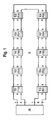
- FIG. 1 is, simplified, the scheme of a hazard detection system shown.
- the central unit ZE which is the alarm center, in the case of larger systems a sub-center or an alarm center or a sub-center connected coupler can act.
- the central unit ZE has a connection A and a connection B for a guided in the ring, embodied by a second wire line field bus whose beginning is accordingly connected to the terminal A and the end to the terminal B of the central unit ZE.
- the fieldbus supplies eg up to 123 subscribers with their operating voltage and at the same time serves the digital communication between the central unit and these subscribers. For the sake of simplicity, only 10 subscribers are represented in a ring R.
- Each participant has a two-pole input a and a two-pole output b.
- T01 to T03 may be fire detectors
- T04 may be an optical or acoustic escape route identifier
- T05 may be an extinguishant controller, and so on.
- the central unit can supply the ring R in an operating mode A via the connection A and / or in operating mode B via the connection B with operating voltage.
- the central unit ZE comprises a logic which determines the operating mode as a function of the state of the fieldbus.
- the logic detects an open circuit or a short on the fieldbus in A-mode, it will attempt to be ready for operation by switching to B-mode or A / B mode, ie powering the fieldbus and communicating between them Terminals A and B off, to maintain.
- FIG. 2 Structure shown as a block diagram. If the fieldbus is not operated as a ring but only as a stitch, the structure is simplified accordingly.
- the subscriber has input terminals a + and a- as well as output terminals b + and b-.
- the field bus embodying two-wire line is connected to the input terminals a + and a-.
- the continuing two-wire line is connected to the output terminals b + and b-, respectively.
- Between the terminals a + and b + is a closed in regular operation disconnector TR, for example, a relay contact or a controlled semiconductor switch.
- the disconnector TR can also lie between the terminals a and b.
- the separator TR comprises two series-arranged FETs as switches, which are selectively, ie programmatically, individually or jointly switchable via switching commands.
- a current sensor IS for example in the form of a current measuring resistor whose current-proportional voltage drop measures an evaluation circuit AS, compares with a maximum value stored in a memory MA and the result and, in the case of an annularly guided field bus, also the direction of current flow to a processor between the terminals a and b transmitted ⁇ P.
- the processor ⁇ P is furthermore connected to a sensor or an actuator S / A, for example to the detection circuit of a scattered light smoke detector or to the control circuit of an extinguishing agent system.
- the processor sends status messages to the central unit ZE in via a communication module KM Fig. 1 and receives from these commands in the form of data telegrams.
- the processor ⁇ P controls the switching state of the disconnector TR.
- the communication module KM can also report the switching state of the disconnector TR to the central unit ZE.
- the evaluation circuit AS queries via the current sensor IS, the current on the fieldbus, that is, the current through the subscriber, in short intervals periodically.
- the maximum value is preferably stored in the memory MA during the commissioning of the alarm system, as well as the current flow direction in normal operation of the ring. If the maximum value is exceeded, the processor ⁇ P starts a timer ZG. Depending on the direction (the sign) of the current, the processor determines ⁇ P after expiration of either a stored delay time VZa or after the lapse of a stored delay time VZb, whether the exceeding of the maximum value of the current characterizing signal persists. Only if this is the case does the processor ⁇ P trigger the opening of the disconnector TR. The resulting performance is then based on Fig. 3 be explained.
- the processor .mu.P receives its internal operating voltage from an energy store ES, for example a capacitor, which is dimensioned so that at least the processor .mu.P and the current measuring circuit IS, AS remain operable at least until the disconnector TR is opened.
- the energy store ES is connected to the line between a + and b + via diodes D1 and D2 on both sides of the disconnector TR in order to prevent the energy store ES from discharging via the short-circuit point in the event of a short circuit.
- the subscriber has a voltage measuring module Sa and Sb on the input side and output side.
- the voltage measurement modules compare the operating voltage present at the input and the output of the subscriber with a stored minimum value and, if not reached, supply a signal to the processor which can interpret this signal by certain routines such as the sensor or actuator S / A control or the data traffic abort with the communication module KM and immediately start the timer ZG. This shortens the time until the necessary opening of the disconnector TR.
- a / D converters can be integrated in the processor ⁇ P and all values to be stored can be stored in a common memory IC.
- Fig. 3 in the ordinate direction, the subscribers T01 to T10 are plotted in the abscissa direction, the delay times VZa and VZb rising from left to right in a symbolic time grid.
- Each of the participants T01 to T10 is assigned a specific delay time for him. This depends on its “distance” from the respective feeding connection of the central unit ZE and the longer, the closer the relevant subscriber is to the feeding connection. By “distance” is meant the number of further participants up to the (respective) connection.
- the subscriber T01 As seen from the A port of the central unit ZE, the first subscriber, but when fed via the B port of the central unit ZE is the last subscriber (T10), the subscriber T01 is at startup of the system as a delay time VZa of Value t10 and assigned as delay time VZb the value t1 for storage, etc. Conversely, for example, the participant T10 as the delay time VZa the value t1 and assigned as delay time VZb the value t10 and stored in this. Consequently, the subscriber T01 has the longest delay time t10 [VZa] and the shortest delay time t1 [VZb], the subscriber T09 the delay times t9 [VZa] and t2 [VZb], etc.
- the subscribers T07 to T06 are supplied (only) with operating voltage via the A connection; T10, however, via the B port. Therefore, for T01 to T06 only the delay times VZa from t10 to t5 are relevant and marked as circles.
- the delay times t4 [VZa] to t1 [VZa], which are not relevant in the case under consideration but are also stored, are shown as dashed circles.
- only the relevant delay times t7 [VZb] to t10 [VZb] are represented as circles for the subscribers T10 to T07.
- the further stored delay times t1 [VZb] to t6 [VZb] are also not shown for the sake of clarity.
- the subscriber T06 with the shortest delay time t5 [VZa] and also the subscriber T07 with the shortest delay time t7 [VZb] are the first to recognize this state. These delay times are additionally marked with "X". These two participants consequently open their separators TR. Thus the fault location is separated from the ring bus. The participants T01 to T05 and the participants T08 to T10 recognize, however, at the end of their respective longer delay times VZa or VZb that the maximum permissible value MA of the current is (again) below. Their disconnectors TR therefore remain closed. Consequently, the previous functioning of the hazard alarm system is restored at least for the participants T01 to T05 and T08 to T10. The functionality can be completely restored, ie also for the subscribers T06 and T07 on both sides of the fault location, if these two subscribers in turn can also process signals from their sensors or commands for their actuators after opening their disconnectors.
- the command of the processor ⁇ P which triggers the opening of the disconnector TR, can be used simultaneously to turn on an LED (not shown), which facilitates the location of the fault location for the maintenance personnel.
Landscapes
- Engineering & Computer Science (AREA)
- Computer Security & Cryptography (AREA)
- Physics & Mathematics (AREA)
- General Physics & Mathematics (AREA)
- Alarm Systems (AREA)
Claims (10)
- Procédé de fonctionnement d'une installation de signalisation de danger avec une unité centrale (centrale ou coupleur) à laquelle sont connectés en parallèle plusieurs abonnés (T01 à T10) par le biais d'un conducteur à deux fils en tant que bus de terrain, abonnés dont chacun comprend une entrée (a) et une sortie (b) pour le bus de terrain, au moins un processeur (µP), un sectionneur TR, commandé par le processeur, entre l'entrée (a) et la sortie (b), un capteur ou organe de régulation (S/A) et un module de communication (KM), caractérisé en ce que, dans chaque abonné (T01 à T10),- le courant est mesuré par l'abonné entre son entrée (a) et sa sortie (b), comparé à une valeur maximale enregistrée et en ce que, si cette dernière est dépassée, un signal qui en est représentatif et qui est adressé au processeur (µP) est produit- et ensuite, si le dépassement de la valeur maximale du courant persiste après l'expiration d'une temporisation (VZ) spécifique à l'abonné, le sectionneur (TR) est ouvert.
- Procédé selon la revendication 1, caractérisé en ce que la temporisation (VZ) spécifique à l'abonné est définie en fonction du nombre des autres abonnés situés entre l'abonné respectif et l'unité centrale (ZE) et est enregistrée dans l'abonné respectif lors de la mise en marche de l'installation de signalisation de danger.
- Procédé selon la revendication 1 ou 2, caractérisé en ce que la temporisation (VZ) spécifique à l'abonné est fixée en tant que VZ = (N+1-i)·t, où N est le nombre d'abonnés (T01 à T10), i est le numéro de position physique de l'abonné compté par la connexion d'alimentation (A, B) de l'unité centrale (ZE), et t est un intervalle de temps qui est plus grand que le temps dont l'abonné a besoin pour traiter complètement sa routine de fonctionnement.
- Procédé selon une des revendications 1 à 3, pour une installation de signalisation de danger dont l'unité centrale (ZE) a une connexion A pour le début du bus de terrain et une connexion B pour la fin du bus de terrain, et alimente ce dernier par le biais de la connexion A et/ou de la connexion B, caractérisé en ce que, lors de la mise en marche de l'installation de signalisation de danger, dans chaque abonné, le sens d'écoulement de courant qui vaut pour le fonctionnement normal et une première temporisation (VZa) pour le cas d'une alimentation par le biais de la connexion A de l'unité centrale (ZE), et une deuxième temporisation (VZb) pour le cas de l'alimentation par le biais de la connexion B de l'unité centrale (ZE) sont enregistrés, et en ce que, en fonctionnement, en cas de dépassement de la valeur maximale enregistrée du courant, le sens de ce dernier entre l'entrée (a) et la sortie (b) de l'abonné est déterminé, et en ce que, en fonction du sens d'écoulement de courant déterminé, le sectionneur (TR) est ouvert soit lors de l'expiration de la première temporisation (VZa), soit lors de l'expiration de la deuxième temporisation (VZb) et lors d'un dépassement persistant de la valeur maximale du courant.
- Procédé selon une des revendications 1 à 4, caractérisé en ce que, lors de l'ouverture du sectionneur (TR), un télégramme de données qui qualifie cette ouverture est envoyé à l'unité centrale (ZE) par le biais du module de communication (KM).
- Procédé selon une des revendications 1 à 5, caractérisé en ce que les abonnés (T01 à T10) sont alimentés à partir d'un accumulateur d'énergie interne en cas de passage au-dessous de la valeur minimale de leur tension de service.
- Procédé selon une des revendications 1 à 6, caractérisé en ce que, dans chaque abonné (T01 à T10), la tension de service présente est mesurée, comparée à une valeur minimale enregistrée et le résultat de la comparaison est fourni au processeur (µP).
- Procédé selon une des revendications 1 à 7, caractérisé en ce que, lorsque le sectionneur (TR) est ouvert, une lampe témoin de l'abonné est activée.
- Installation de signalisation de danger avec une unité centrale (centrale ou coupleur) à laquelle sont connectés plusieurs abonnés (T01 à T10) par le biais d'un conducteur à deux fils en tant que bus de terrain, chaque abonné comprenant- une entrée (a) et une sortie (b) pour le bus de terrain,- au moins un processeur (µP),- un sectionneur TR, commandé par le processeur (µP), entre l'entrée (a) et la sortie (b),- un capteur ou organe de régulation (S/A),- un capteur de courant (IS) pour la mesure du courant entre l'entrée (a) et la sortie (b) de l'abonné et- un module de communication (KM) pour l'échange de télégrammes de données avec l'unité centrale (ZE), caractérisée par- au moins une mémoire (VZa/Vzb) pour au moins une temporisation (VZ) spécifique à l'abonné,- une autre mémoire pour la mise en mémoire d'au moins le montant de la valeur maximale du courant admissible en fonctionnement normal entre l'entrée (a) et la sortie (b) de l'abonné,- un circuit d'analyse (AS) qui compare le courant mesuré à la valeur maximale enregistrée et fournit au processeur (µP) le résultat de la comparaison et qui, dans le cas d'un bus de terrain connecté de façon annulaire, fournit également le sens du courant,- et un accumulateur d'énergie pour le fonctionnement du processeur (µP) lors de la disparition de la tension de service de l'abonné,et l'installation étant configurée de telle sorte que, lors du dépassement de la valeur maximale et en cas de persistance du dépassement après l'expiration de la temporisation spécifique à l'abonné, le sectionneur est ouvert.
- Installation de signalisation de danger selon la revendication 9, caractérisée par un module de mesure de tension qui compare la tension de service présente sur l'entrée (a) ou sur la sortie (b) de l'abonné avec une valeur minimale enregistrée et qui fournit un signal au processeur (µP) en cas de sous-tension.
Applications Claiming Priority (1)
| Application Number | Priority Date | Filing Date | Title |
|---|---|---|---|
| DE102010022560.6A DE102010022560B4 (de) | 2010-06-02 | 2010-06-02 | Verfahren zum Betreiben einer Gefahrenmeldeanlage |
Publications (2)
| Publication Number | Publication Date |
|---|---|
| EP2393073A1 EP2393073A1 (fr) | 2011-12-07 |
| EP2393073B1 true EP2393073B1 (fr) | 2013-07-31 |
Family
ID=44544248
Family Applications (1)
| Application Number | Title | Priority Date | Filing Date |
|---|---|---|---|
| EP20110155545 Active EP2393073B1 (fr) | 2010-06-02 | 2011-02-23 | Procédé destiné au fonctionnement d'une installation d'alerte aux dangers |
Country Status (3)
| Country | Link |
|---|---|
| EP (1) | EP2393073B1 (fr) |
| DE (1) | DE102010022560B4 (fr) |
| ES (1) | ES2433668T3 (fr) |
Cited By (1)
| Publication number | Priority date | Publication date | Assignee | Title |
|---|---|---|---|---|
| US10725096B2 (en) | 2017-08-10 | 2020-07-28 | Wagner Group Gmbh | Control and monitoring module |
Families Citing this family (5)
| Publication number | Priority date | Publication date | Assignee | Title |
|---|---|---|---|---|
| EP2701132B1 (fr) * | 2012-08-23 | 2018-07-04 | Novar GmbH | Dispositif d'alarme comprenant une unité de stockage d'énergie local et système d'alarme basé sur le bus |
| DE102012020127B4 (de) * | 2012-10-15 | 2016-06-09 | Telesystems Thorwarth Gmbh | Anordnung zur Überwachung und Brandfrühsterkennung für mehrere brand- und/oder explosionsgefährdete Gefäße und/oder Gehäuse |
| DE102020201702B4 (de) | 2019-02-11 | 2025-02-20 | Hekatron Vertriebs Gmbh | Verfahren zur Leitungsüberwachung in einem Gefahrenmeldesystem sowie Leitungsüberwachung für ein Gefahrenmeldesystem |
| EP3748599B1 (fr) | 2019-06-03 | 2021-07-28 | Siemens Schweiz AG | Procédé pour opérer et tester un système de signalisation de danger avec un système de bus, détecteurs pour connexion à un système de bus et système de signalisation de danger avec un système de bus. |
| CN110261757A (zh) * | 2019-06-10 | 2019-09-20 | 南京宏泰半导体科技有限公司 | 一种数字隔离芯片测试方法和系统 |
Family Cites Families (3)
| Publication number | Priority date | Publication date | Assignee | Title |
|---|---|---|---|---|
| DE19611945C1 (de) * | 1996-03-26 | 1997-11-20 | Daimler Benz Ag | Einrichtung für den busvernetzten Betrieb eines elektronischen Gerätes mit Microcontroller sowie deren Verwendung |
| DE19813922A1 (de) * | 1998-03-28 | 1999-09-30 | Telefunken Microelectron | Verfahren zum Betreiben eines über eine Busleitung vernetzten Rückhaltesystems bei einem Kurzschluß |
| DE202007006026U1 (de) * | 2007-04-25 | 2008-08-28 | Pepperl + Fuchs Gmbh | Slave-Modul mit mindestens zwei Ausgangsslaves |
-
2010
- 2010-06-02 DE DE102010022560.6A patent/DE102010022560B4/de not_active Expired - Fee Related
-
2011
- 2011-02-23 ES ES11155545T patent/ES2433668T3/es active Active
- 2011-02-23 EP EP20110155545 patent/EP2393073B1/fr active Active
Cited By (1)
| Publication number | Priority date | Publication date | Assignee | Title |
|---|---|---|---|---|
| US10725096B2 (en) | 2017-08-10 | 2020-07-28 | Wagner Group Gmbh | Control and monitoring module |
Also Published As
| Publication number | Publication date |
|---|---|
| ES2433668T3 (es) | 2013-12-12 |
| EP2393073A1 (fr) | 2011-12-07 |
| DE102010022560A1 (de) | 2011-12-08 |
| DE102010022560B4 (de) | 2017-03-23 |
Similar Documents
| Publication | Publication Date | Title |
|---|---|---|
| EP2393073B1 (fr) | Procédé destiné au fonctionnement d'une installation d'alerte aux dangers | |
| EP0067339B1 (fr) | Méthode et arrangement pour détecter des perturbations dans des systèmes de signalisation de risques, en particulier signalisation d'incendie | |
| EP2720098B1 (fr) | Système de sécurité pour une installation comprenant un chemin de signal de test avec un chemin de retour | |
| EP2720094B1 (fr) | Système de sécurité | |
| EP0279168B1 (fr) | Circuit pour l'alimentation de courant d'une pluralité de consommateurs | |
| DE69514445T2 (de) | Übertragungsleitung-Überwachungsvorrichtung zur Anwendung in einem Feueralarmsystem | |
| DE3730103C2 (fr) | ||
| EP0403763A2 (fr) | Méthode et système d'interconnexion de calculateurs ou de réseaux de calculateurs | |
| DE19643092A1 (de) | Feld-Datenbussystem | |
| EP2017803B1 (fr) | Système de conservation des fonctions et de sécurisation actif pour réseaux de haut-parleurs d'alarmes dans une technique de conduite annulaire à deux fils | |
| EP2203912B1 (fr) | Dispositif de séparation équipé d'un collecteur d'énergie pour une ligne électrique acheminant de l'énergie | |
| DE3522418A1 (de) | Einrichtung zur meldung des belegungszustandes von gleisabschnitten im bereich eines stellwerks | |
| DE2833761B2 (de) | Schaltungsanordnung zur Überwachung des Zustande von Signalanlagen, insbesondere von StraBenverkehrs-Lichtsignalanlagen | |
| DE112013002661T5 (de) | Segment mit einer Fehlerschutzeinrichtung für ein zweidrahtiges, kombiniert verbundenes Energie- und Datennetzsystem | |
| EP0924585B1 (fr) | Dispositif de surveillance d'actionneur de porte de garage | |
| EP1687681A2 (fr) | Reseau, notamment reseau pa profibus, a proprietes de redondance, element de ramification pour appareil d'abonne dans un reseau de ce type, gestionnaire de redondance pour un reseau de ce type et procede pour faire fonctionner un reseau de ce type | |
| DE69400046T2 (de) | Verfahren und Anordnung zum Schutz eines seriellen Bus gegen Kurzschluss | |
| EP2423897B1 (fr) | Installation d'alerte aux dangers et son procédé de fonctionnement | |
| EP2428942B1 (fr) | Installation d'alerte aux dangers dotée de deux vitesses de transmission de données | |
| EP2625678B1 (fr) | Procédé servant à faire fonctionner une installation d'annonces orales | |
| EP0698321A1 (fr) | Reseau de communication a plusieurs stations et son procede de fonctionnement | |
| DE4322841C2 (de) | Gefahrenmeldeanlage | |
| EP0809361B1 (fr) | Dispositif électronique de commutation et circuit pour la surveillance d'une installation technique | |
| EP2520988B1 (fr) | Dispositif de surveillance de systèmes de surveillance de réseaux électriques | |
| DE3637681A1 (de) | Gefahrenmeldeanlage nach dem pulsmeldesystem |
Legal Events
| Date | Code | Title | Description |
|---|---|---|---|
| AK | Designated contracting states |
Kind code of ref document: A1 Designated state(s): AL AT BE BG CH CY CZ DE DK EE ES FI FR GB GR HR HU IE IS IT LI LT LU LV MC MK MT NL NO PL PT RO RS SE SI SK SM TR |
|
| AX | Request for extension of the european patent |
Extension state: BA ME |
|
| PUAI | Public reference made under article 153(3) epc to a published international application that has entered the european phase |
Free format text: ORIGINAL CODE: 0009012 |
|
| RIN1 | Information on inventor provided before grant (corrected) |
Inventor name: UNGEMACH, PETER |
|
| 17P | Request for examination filed |
Effective date: 20120601 |
|
| GRAP | Despatch of communication of intention to grant a patent |
Free format text: ORIGINAL CODE: EPIDOSNIGR1 |
|
| GRAJ | Information related to disapproval of communication of intention to grant by the applicant or resumption of examination proceedings by the epo deleted |
Free format text: ORIGINAL CODE: EPIDOSDIGR1 |
|
| GRAP | Despatch of communication of intention to grant a patent |
Free format text: ORIGINAL CODE: EPIDOSNIGR1 |
|
| GRAS | Grant fee paid |
Free format text: ORIGINAL CODE: EPIDOSNIGR3 |
|
| GRAA | (expected) grant |
Free format text: ORIGINAL CODE: 0009210 |
|
| AK | Designated contracting states |
Kind code of ref document: B1 Designated state(s): AL AT BE BG CH CY CZ DE DK EE ES FI FR GB GR HR HU IE IS IT LI LT LU LV MC MK MT NL NO PL PT RO RS SE SI SK SM TR |
|
| REG | Reference to a national code |
Ref country code: GB Ref legal event code: FG4D Free format text: NOT ENGLISH Ref country code: CH Ref legal event code: EP |
|
| REG | Reference to a national code |
Ref country code: AT Ref legal event code: REF Ref document number: 625032 Country of ref document: AT Kind code of ref document: T Effective date: 20130815 |
|
| REG | Reference to a national code |
Ref country code: IE Ref legal event code: FG4D Free format text: LANGUAGE OF EP DOCUMENT: GERMAN |
|
| REG | Reference to a national code |
Ref country code: DE Ref legal event code: R096 Ref document number: 502011001115 Country of ref document: DE Effective date: 20130919 |
|
| REG | Reference to a national code |
Ref country code: ES Ref legal event code: FG2A Ref document number: 2433668 Country of ref document: ES Kind code of ref document: T3 Effective date: 20131212 |
|
| REG | Reference to a national code |
Ref country code: NL Ref legal event code: VDEP Effective date: 20130731 |
|
| REG | Reference to a national code |
Ref country code: LT Ref legal event code: MG4D |
|
| PG25 | Lapsed in a contracting state [announced via postgrant information from national office to epo] |
Ref country code: NO Free format text: LAPSE BECAUSE OF FAILURE TO SUBMIT A TRANSLATION OF THE DESCRIPTION OR TO PAY THE FEE WITHIN THE PRESCRIBED TIME-LIMIT Effective date: 20131031 Ref country code: CY Free format text: LAPSE BECAUSE OF FAILURE TO SUBMIT A TRANSLATION OF THE DESCRIPTION OR TO PAY THE FEE WITHIN THE PRESCRIBED TIME-LIMIT Effective date: 20130731 Ref country code: PT Free format text: LAPSE BECAUSE OF FAILURE TO SUBMIT A TRANSLATION OF THE DESCRIPTION OR TO PAY THE FEE WITHIN THE PRESCRIBED TIME-LIMIT Effective date: 20131202 Ref country code: HR Free format text: LAPSE BECAUSE OF FAILURE TO SUBMIT A TRANSLATION OF THE DESCRIPTION OR TO PAY THE FEE WITHIN THE PRESCRIBED TIME-LIMIT Effective date: 20130731 Ref country code: IS Free format text: LAPSE BECAUSE OF FAILURE TO SUBMIT A TRANSLATION OF THE DESCRIPTION OR TO PAY THE FEE WITHIN THE PRESCRIBED TIME-LIMIT Effective date: 20131130 Ref country code: LT Free format text: LAPSE BECAUSE OF FAILURE TO SUBMIT A TRANSLATION OF THE DESCRIPTION OR TO PAY THE FEE WITHIN THE PRESCRIBED TIME-LIMIT Effective date: 20130731 Ref country code: SE Free format text: LAPSE BECAUSE OF FAILURE TO SUBMIT A TRANSLATION OF THE DESCRIPTION OR TO PAY THE FEE WITHIN THE PRESCRIBED TIME-LIMIT Effective date: 20130731 |
|
| PG25 | Lapsed in a contracting state [announced via postgrant information from national office to epo] |
Ref country code: NL Free format text: LAPSE BECAUSE OF FAILURE TO SUBMIT A TRANSLATION OF THE DESCRIPTION OR TO PAY THE FEE WITHIN THE PRESCRIBED TIME-LIMIT Effective date: 20130731 Ref country code: FI Free format text: LAPSE BECAUSE OF FAILURE TO SUBMIT A TRANSLATION OF THE DESCRIPTION OR TO PAY THE FEE WITHIN THE PRESCRIBED TIME-LIMIT Effective date: 20130731 Ref country code: LV Free format text: LAPSE BECAUSE OF FAILURE TO SUBMIT A TRANSLATION OF THE DESCRIPTION OR TO PAY THE FEE WITHIN THE PRESCRIBED TIME-LIMIT Effective date: 20130731 Ref country code: SI Free format text: LAPSE BECAUSE OF FAILURE TO SUBMIT A TRANSLATION OF THE DESCRIPTION OR TO PAY THE FEE WITHIN THE PRESCRIBED TIME-LIMIT Effective date: 20130731 Ref country code: GR Free format text: LAPSE BECAUSE OF FAILURE TO SUBMIT A TRANSLATION OF THE DESCRIPTION OR TO PAY THE FEE WITHIN THE PRESCRIBED TIME-LIMIT Effective date: 20131101 Ref country code: PL Free format text: LAPSE BECAUSE OF FAILURE TO SUBMIT A TRANSLATION OF THE DESCRIPTION OR TO PAY THE FEE WITHIN THE PRESCRIBED TIME-LIMIT Effective date: 20130731 |
|
| PG25 | Lapsed in a contracting state [announced via postgrant information from national office to epo] |
Ref country code: RO Free format text: LAPSE BECAUSE OF FAILURE TO SUBMIT A TRANSLATION OF THE DESCRIPTION OR TO PAY THE FEE WITHIN THE PRESCRIBED TIME-LIMIT Effective date: 20130731 Ref country code: DK Free format text: LAPSE BECAUSE OF FAILURE TO SUBMIT A TRANSLATION OF THE DESCRIPTION OR TO PAY THE FEE WITHIN THE PRESCRIBED TIME-LIMIT Effective date: 20130731 Ref country code: EE Free format text: LAPSE BECAUSE OF FAILURE TO SUBMIT A TRANSLATION OF THE DESCRIPTION OR TO PAY THE FEE WITHIN THE PRESCRIBED TIME-LIMIT Effective date: 20130731 Ref country code: SK Free format text: LAPSE BECAUSE OF FAILURE TO SUBMIT A TRANSLATION OF THE DESCRIPTION OR TO PAY THE FEE WITHIN THE PRESCRIBED TIME-LIMIT Effective date: 20130731 Ref country code: CZ Free format text: LAPSE BECAUSE OF FAILURE TO SUBMIT A TRANSLATION OF THE DESCRIPTION OR TO PAY THE FEE WITHIN THE PRESCRIBED TIME-LIMIT Effective date: 20130731 |
|
| PLBE | No opposition filed within time limit |
Free format text: ORIGINAL CODE: 0009261 |
|
| STAA | Information on the status of an ep patent application or granted ep patent |
Free format text: STATUS: NO OPPOSITION FILED WITHIN TIME LIMIT |
|
| 26N | No opposition filed |
Effective date: 20140502 |
|
| REG | Reference to a national code |
Ref country code: DE Ref legal event code: R097 Ref document number: 502011001115 Country of ref document: DE Effective date: 20140502 |
|
| BERE | Be: lapsed |
Owner name: NOVAR G.M.B.H. Effective date: 20140228 |
|
| PG25 | Lapsed in a contracting state [announced via postgrant information from national office to epo] |
Ref country code: MC Free format text: LAPSE BECAUSE OF FAILURE TO SUBMIT A TRANSLATION OF THE DESCRIPTION OR TO PAY THE FEE WITHIN THE PRESCRIBED TIME-LIMIT Effective date: 20130731 Ref country code: LU Free format text: LAPSE BECAUSE OF FAILURE TO SUBMIT A TRANSLATION OF THE DESCRIPTION OR TO PAY THE FEE WITHIN THE PRESCRIBED TIME-LIMIT Effective date: 20140223 |
|
| REG | Reference to a national code |
Ref country code: CH Ref legal event code: PL |
|
| PG25 | Lapsed in a contracting state [announced via postgrant information from national office to epo] |
Ref country code: LI Free format text: LAPSE BECAUSE OF NON-PAYMENT OF DUE FEES Effective date: 20140228 Ref country code: CH Free format text: LAPSE BECAUSE OF NON-PAYMENT OF DUE FEES Effective date: 20140228 |
|
| REG | Reference to a national code |
Ref country code: IE Ref legal event code: MM4A |
|
| PG25 | Lapsed in a contracting state [announced via postgrant information from national office to epo] |
Ref country code: IE Free format text: LAPSE BECAUSE OF NON-PAYMENT OF DUE FEES Effective date: 20140223 Ref country code: BE Free format text: LAPSE BECAUSE OF NON-PAYMENT OF DUE FEES Effective date: 20140228 |
|
| REG | Reference to a national code |
Ref country code: FR Ref legal event code: PLFP Year of fee payment: 6 |
|
| PG25 | Lapsed in a contracting state [announced via postgrant information from national office to epo] |
Ref country code: MT Free format text: LAPSE BECAUSE OF FAILURE TO SUBMIT A TRANSLATION OF THE DESCRIPTION OR TO PAY THE FEE WITHIN THE PRESCRIBED TIME-LIMIT Effective date: 20130731 |
|
| PG25 | Lapsed in a contracting state [announced via postgrant information from national office to epo] |
Ref country code: SM Free format text: LAPSE BECAUSE OF FAILURE TO SUBMIT A TRANSLATION OF THE DESCRIPTION OR TO PAY THE FEE WITHIN THE PRESCRIBED TIME-LIMIT Effective date: 20130731 |
|
| PG25 | Lapsed in a contracting state [announced via postgrant information from national office to epo] |
Ref country code: RS Free format text: LAPSE BECAUSE OF NON-PAYMENT OF DUE FEES Effective date: 20130731 Ref country code: BG Free format text: LAPSE BECAUSE OF FAILURE TO SUBMIT A TRANSLATION OF THE DESCRIPTION OR TO PAY THE FEE WITHIN THE PRESCRIBED TIME-LIMIT Effective date: 20130731 |
|
| PG25 | Lapsed in a contracting state [announced via postgrant information from national office to epo] |
Ref country code: HU Free format text: LAPSE BECAUSE OF FAILURE TO SUBMIT A TRANSLATION OF THE DESCRIPTION OR TO PAY THE FEE WITHIN THE PRESCRIBED TIME-LIMIT; INVALID AB INITIO Effective date: 20110223 Ref country code: TR Free format text: LAPSE BECAUSE OF FAILURE TO SUBMIT A TRANSLATION OF THE DESCRIPTION OR TO PAY THE FEE WITHIN THE PRESCRIBED TIME-LIMIT Effective date: 20130731 |
|
| REG | Reference to a national code |
Ref country code: FR Ref legal event code: PLFP Year of fee payment: 7 |
|
| REG | Reference to a national code |
Ref country code: AT Ref legal event code: MM01 Ref document number: 625032 Country of ref document: AT Kind code of ref document: T Effective date: 20160223 |
|
| PG25 | Lapsed in a contracting state [announced via postgrant information from national office to epo] |
Ref country code: AT Free format text: LAPSE BECAUSE OF NON-PAYMENT OF DUE FEES Effective date: 20160223 |
|
| REG | Reference to a national code |
Ref country code: FR Ref legal event code: PLFP Year of fee payment: 8 |
|
| PG25 | Lapsed in a contracting state [announced via postgrant information from national office to epo] |
Ref country code: MK Free format text: LAPSE BECAUSE OF FAILURE TO SUBMIT A TRANSLATION OF THE DESCRIPTION OR TO PAY THE FEE WITHIN THE PRESCRIBED TIME-LIMIT Effective date: 20130731 |
|
| PG25 | Lapsed in a contracting state [announced via postgrant information from national office to epo] |
Ref country code: AL Free format text: LAPSE BECAUSE OF FAILURE TO SUBMIT A TRANSLATION OF THE DESCRIPTION OR TO PAY THE FEE WITHIN THE PRESCRIBED TIME-LIMIT Effective date: 20130731 |
|
| PGFP | Annual fee paid to national office [announced via postgrant information from national office to epo] |
Ref country code: FR Payment date: 20210223 Year of fee payment: 11 |
|
| PGFP | Annual fee paid to national office [announced via postgrant information from national office to epo] |
Ref country code: ES Payment date: 20210317 Year of fee payment: 11 Ref country code: GB Payment date: 20210223 Year of fee payment: 11 |
|
| PGFP | Annual fee paid to national office [announced via postgrant information from national office to epo] |
Ref country code: IT Payment date: 20220221 Year of fee payment: 12 |
|
| GBPC | Gb: european patent ceased through non-payment of renewal fee |
Effective date: 20220223 |
|
| PG25 | Lapsed in a contracting state [announced via postgrant information from national office to epo] |
Ref country code: FR Free format text: LAPSE BECAUSE OF NON-PAYMENT OF DUE FEES Effective date: 20220228 |
|
| PG25 | Lapsed in a contracting state [announced via postgrant information from national office to epo] |
Ref country code: GB Free format text: LAPSE BECAUSE OF NON-PAYMENT OF DUE FEES Effective date: 20220223 |
|
| REG | Reference to a national code |
Ref country code: ES Ref legal event code: FD2A Effective date: 20230404 |
|
| PG25 | Lapsed in a contracting state [announced via postgrant information from national office to epo] |
Ref country code: ES Free format text: LAPSE BECAUSE OF NON-PAYMENT OF DUE FEES Effective date: 20220224 |
|
| P01 | Opt-out of the competence of the unified patent court (upc) registered |
Effective date: 20230523 |
|
| PG25 | Lapsed in a contracting state [announced via postgrant information from national office to epo] |
Ref country code: IT Free format text: LAPSE BECAUSE OF NON-PAYMENT OF DUE FEES Effective date: 20230223 |
|
| PGFP | Annual fee paid to national office [announced via postgrant information from national office to epo] |
Ref country code: DE Payment date: 20260220 Year of fee payment: 16 |