EP2394824B1 - Pneus pour véhicules de chantier - Google Patents
Pneus pour véhicules de chantier Download PDFInfo
- Publication number
- EP2394824B1 EP2394824B1 EP10738312.7A EP10738312A EP2394824B1 EP 2394824 B1 EP2394824 B1 EP 2394824B1 EP 10738312 A EP10738312 A EP 10738312A EP 2394824 B1 EP2394824 B1 EP 2394824B1
- Authority
- EP
- European Patent Office
- Prior art keywords
- tire
- groove
- width direction
- circumferential direction
- construction vehicle
- Prior art date
- Legal status (The legal status is an assumption and is not a legal conclusion. Google has not performed a legal analysis and makes no representation as to the accuracy of the status listed.)
- Not-in-force
Links
- 238000010276 construction Methods 0.000 title claims description 37
- 238000003491 array Methods 0.000 claims description 6
- 230000000052 comparative effect Effects 0.000 description 9
- 230000006866 deterioration Effects 0.000 description 9
- 238000010586 diagram Methods 0.000 description 7
- 238000010008 shearing Methods 0.000 description 6
- 238000011156 evaluation Methods 0.000 description 5
- 230000007423 decrease Effects 0.000 description 3
- 230000000694 effects Effects 0.000 description 3
- 238000000034 method Methods 0.000 description 2
- 230000002349 favourable effect Effects 0.000 description 1
- 238000012986 modification Methods 0.000 description 1
- 230000004048 modification Effects 0.000 description 1
- 230000000191 radiation effect Effects 0.000 description 1
- 238000000926 separation method Methods 0.000 description 1
Images

Classifications
-
- B—PERFORMING OPERATIONS; TRANSPORTING
- B60—VEHICLES IN GENERAL
- B60C—VEHICLE TYRES; TYRE INFLATION; TYRE CHANGING; CONNECTING VALVES TO INFLATABLE ELASTIC BODIES IN GENERAL; DEVICES OR ARRANGEMENTS RELATED TO TYRES
- B60C11/00—Tyre tread bands; Tread patterns; Anti-skid inserts
- B60C11/03—Tread patterns
- B60C11/12—Tread patterns characterised by the use of narrow slits or incisions, e.g. sipes
-
- B—PERFORMING OPERATIONS; TRANSPORTING
- B60—VEHICLES IN GENERAL
- B60C—VEHICLE TYRES; TYRE INFLATION; TYRE CHANGING; CONNECTING VALVES TO INFLATABLE ELASTIC BODIES IN GENERAL; DEVICES OR ARRANGEMENTS RELATED TO TYRES
- B60C11/00—Tyre tread bands; Tread patterns; Anti-skid inserts
- B60C11/03—Tread patterns
- B60C11/0311—Patterns comprising tread lugs arranged parallel or oblique to the axis of rotation
-
- B—PERFORMING OPERATIONS; TRANSPORTING
- B60—VEHICLES IN GENERAL
- B60C—VEHICLE TYRES; TYRE INFLATION; TYRE CHANGING; CONNECTING VALVES TO INFLATABLE ELASTIC BODIES IN GENERAL; DEVICES OR ARRANGEMENTS RELATED TO TYRES
- B60C11/00—Tyre tread bands; Tread patterns; Anti-skid inserts
- B60C11/03—Tread patterns
- B60C2011/0337—Tread patterns characterised by particular design features of the pattern
- B60C2011/0339—Grooves
- B60C2011/0341—Circumferential grooves
- B60C2011/0346—Circumferential grooves with zigzag shape
-
- B—PERFORMING OPERATIONS; TRANSPORTING
- B60—VEHICLES IN GENERAL
- B60C—VEHICLE TYRES; TYRE INFLATION; TYRE CHANGING; CONNECTING VALVES TO INFLATABLE ELASTIC BODIES IN GENERAL; DEVICES OR ARRANGEMENTS RELATED TO TYRES
- B60C11/00—Tyre tread bands; Tread patterns; Anti-skid inserts
- B60C11/03—Tread patterns
- B60C2011/0337—Tread patterns characterised by particular design features of the pattern
- B60C2011/0339—Grooves
- B60C2011/0341—Circumferential grooves
- B60C2011/0348—Narrow grooves, i.e. having a width of less than 4 mm
-
- B—PERFORMING OPERATIONS; TRANSPORTING
- B60—VEHICLES IN GENERAL
- B60C—VEHICLE TYRES; TYRE INFLATION; TYRE CHANGING; CONNECTING VALVES TO INFLATABLE ELASTIC BODIES IN GENERAL; DEVICES OR ARRANGEMENTS RELATED TO TYRES
- B60C11/00—Tyre tread bands; Tread patterns; Anti-skid inserts
- B60C11/03—Tread patterns
- B60C2011/0337—Tread patterns characterised by particular design features of the pattern
- B60C2011/0339—Grooves
- B60C2011/0341—Circumferential grooves
- B60C2011/0355—Circumferential grooves characterised by depth
-
- B—PERFORMING OPERATIONS; TRANSPORTING
- B60—VEHICLES IN GENERAL
- B60C—VEHICLE TYRES; TYRE INFLATION; TYRE CHANGING; CONNECTING VALVES TO INFLATABLE ELASTIC BODIES IN GENERAL; DEVICES OR ARRANGEMENTS RELATED TO TYRES
- B60C2200/00—Tyres specially adapted for particular applications
- B60C2200/06—Tyres specially adapted for particular applications for heavy duty vehicles
- B60C2200/065—Tyres specially adapted for particular applications for heavy duty vehicles for construction vehicles
Definitions
- the present invention relates to a pneumatic tire, and in particular, to a pneumatic tire for a construction vehicle applicable to a dump truck or other construction vehicles, which are mainly used in a construction site, a mine and the like.
- a conventional pneumatic tire for a construction vehicle has plural lug grooves located at both sides of the tread in the tire width direction.
- the pneumatic tire for the construction vehicle for the purpose of improving a wear life of the tire, it is general to increase a tread gauge or reduce the area of groove portions to increase a tread volume.
- the heat release property at the tread portion tends to deteriorate especially when the tire rotates with load, in other words, the method described above tends to cause rise in temperatures at the tread portion.
- the rise in temperatures at the tread portion as described above unfavorably causes problems such as heat separation at the tread portion.
- Patent Document 1 describes a tire for a construction vehicle that suppresses deterioration in the heat release property, by employing a tread having a predetermined lateral narrow groove to efficiently deliver the wind flowing in a tread groove into the lateral narrow groove and air-cool the center portion of the tire.
- Patent Document 2 discloses a pneumatic tire capable of reducing partial wear at a leading edge without largely reducing rigidity of a land portion, by providing a predetermined lateral sub-groove at each block land portion forming a shoulder area of the tread, so that the leading edge can leave a road surface rapidly at the time when the leading edge kicks out the road surface.
- JP2005-297909 which shows a pneumatic tire according to the preamble of claim 1.
- An object of the present invention is to provide a pneumatic tire for a construction vehicle capable of suppressing deterioration in heat release property while maintaining high wear resistance property especially when used as driving wheels, by optimizing a tread.
- the present inventor made a keen study to solve the above-mentioned problems of the pneumatic tire for the construction vehicle having a tread divided into a central area and two side areas located at both sides of the central area in a tire width direction, and a plurality of lug grooves arranged in each of the side areas, and, as a result, found that it is possible to reduce the shearing force of the tire at the kick-off side, and improve the wear resistance, by configuring the pneumatic tire for the construction vehicle such that: the central area is provided with a central narrow groove continuously extending along the tire circumferential direction in a zigzag form and formed by alternately connecting a first inclined groove portion extending at a predetermined angle with respect to a tire circumferential direction and a second inclined groove portion extending at an opposite angle to the first inclined groove portion with respect to the tire circumferential direction; each of the side areas is provided with a side narrow groove passing through a tire width direction inner side portion of each of the lug grooves and extending in the tire circumferential direction;
- a polygonal block land precedingly contacting with the ground drags a polygonal block opposing the preceding polygonal block land portion across the central narrow groove at the time of traveling, and the dragged polygonal block is in a deformed state before contacting with the ground.
- This causes a shearing force to occur between the road surface and the dragged polygonal block land upon contact of the dragged polygonal block with the road surface, whereby it is possible to improve the traction performance.
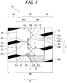
- FIG. 1 is a diagram schematically illustrating a part of a tread according to an embodiment of a pneumatic tire for a construction vehicle of the present invention
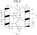
- FIG 2 and FIG. 3 are diagrams each schematically illustrating a part of a tread according to another embodiments of a pneumatic tire for a construction vehicle of the present invention
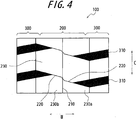
- FIG. 4 is a diagram schematically illustrating a part of a tread of a conventional pneumatic tire for a construction vehicle.
- the direction of the arrow C in each of the drawings represents a tire circumferential direction
- the direction of the arrow W represents a tire width direction.
- a tread 10 is divided into a central area 20, and two side areas 30 located at both sides of the central area 20 in the tire width direction.
- each of the side areas 30 has plural lug grooves 31.
- the central area 20 refers to an area within 50% or lower of the tread width with a tire equator E being as the center
- the side area 30 refers to an area other than the central area 20 in the tread.
- the central area 20 is provided with a central narrow groove 21 continuously extending along the tire circumferential direction in a zigzag form and formed by alternately connecting a first inclined groove portion 21a extending at a predetermined angle with respect to the tire circumferential direction and a second inclined groove portion 21b extending at an opposite angle to the first inclined groove portion 21 a with respect to the tire circumferential direction; each of the side areas 30 is provided with a side narrow groove 32 passing through a tire width direction inner side portion 31 a of each of the lug grooves 31 and extending in the tire circumferential direction; the tire width direction inner side portion 31 a of each of the lug grooves 31 is arranged to face a proximate joint portion 21c 2 of joint portions 21c 1 and 21c 2 of the first inclined groove portion and the second inclined groove portion in the tire width direction; a width direction narrow groove 22 is provided so as to extend and pass between the tire width direction inner side portion 31a of each of the lug grooves and
- the polygonal block arrays 24a and 24b according to the present invention are located on both sides of the central narrow groove 21 extending in the tire circumferential direction C in the zigzag form, and a top end portion of each of the polygonal blocks 23a and 23b is adjacent to polygonal blocks extending past a tire equatorial plane E and facing the top end portion. Therefore, in the case where the tires are used in driving wheels of a dump truck and the like, a polygonal block land portion precedingly contacting with the ground (polygonal block land portion 23a in FIG.
- a conventional tread 100 has polygonal block land portions 230 located at both sides of a straight central narrow groove 210 extending along the tire circumferential direction. Therefore, unlike the tread as described above, the traction improvement due to the shearing force between the dragged polygonal block and the road surface cannot be obtained at the time of traveling, and hence, the wear resistance cannot be sufficiently improved.
- the central narrow groove 21 is provided in the central area 20 in a manner that the first inclined groove portion 21a and the second inclined groove portion 21b are alternately jointed, and continuously extends along the tire circumferential direction in a zigzag form.
- a groove depth of the central narrow groove 21 is 60% or more of a groove depth of the lug groove. This is because, in the case where the groove depth of the central narrow groove 21 is less than 60%, the tread wears and the central narrow groove 21 vanishes at the end of tire use, and hence, there is a possibility that the effect of the present invention cannot be sufficiently obtained.
- amplitude w1 of the shape in which the central narrow groove 21 extends is in the range of 5% to 30% of the tread width TW.
- the amplitude w1 is less than 5%, a force for pulling the part of the polygonal block 23 is undesirably small, and hence, there is a possibility that the traction cannot be sufficiently improved and the wear resistance cannot be sufficiently improved.
- the amplitude w1 exceeds 30%, the block rigidity at the center portion decreases, and hence, the wear property cannot be improved.
- the first inclined groove portion 21a extends at an angle a in the range of 20° to 50° with respect to the tire circumferential direction.
- the angle a is less than 20°, a force for dragging the part of the polygonal block 23 is undesirably small, and hence, there is a possibility that the traction cannot be sufficiently improved and the wear resistance cannot be sufficiently improved.
- the angle a exceeds 50°, the block rigidity at the center portion decreases, and hence, the wear property cannot be improved.
- the second inclined groove portion 21b extends at an angle in the range of -20° to -50° with respect to the tire circumferential direction.
- a groove width w2 of the central narrow groove 21 is in the range of 3% to 8% of an arrangement pitch A of the block land portions 23. This is because, in the case where the groove width w2 of the central narrow groove 21 is less than 3% of the arrangement pitch, the groove width is undesirably narrow, and hence, a heat-radiation effect cannot be obtained, possibly causing deterioration in the heat release property. On the other hand, in the case where the groove width w2 exceeds 8%, the force for pulling the part of the polygonal block 23 is undesirably small, and hence, there is a possibility that the traction cannot be sufficiently improved and the wear resistance cannot be sufficiently improved.
- the side narrow grooves 32 are grooves passing through the tire width direction inner side portion 31a of the lug groove 31 and extending in the tire circumferential direction, and the configuration thereof is not specifically limited.
- the tire width direction inner side portion 31a of the lug groove 31 refers to a portion of the lug groove 31 extending from a position where the groove width thereof starts to decrease, to a top end on the inner side of the lug groove 31 in the tire width direction.
- width direction narrow grooves 22 are grooves extending and communicating between the tire width direction inner side portion 31a of the lug groove 31 and the proximate joint portion 21c 2 of the central narrow groove 21, and the other configurations thereof are not specifically limited.
- each of the width direction narrow grooves 22 has a groove width in the range of 3% to 8% of the arrangement pitch A of the block land portion 23.
- the width groove is undesirably narrow, and hence, the heat radiation effect cannot be obtained, possibly causing deterioration in the heat release property.
- the groove width thereof exceeds 8%, the force for dragging the part of the polygonal block 23 is undesirably small, and hence, there is a possibility that the traction cannot be sufficiently improved and the wear resistance cannot be sufficiently improved.
- first inclined groove portion 21 a, the second inclined groove portion 21 b and the width direction narrow groove 22 are brought into contact with each other, and opposed groove walls of the side narrow groove 32 are not brought into contact with each other.
- the groove walls of the side narrow groove 22 are not closed, whereby it is possible to maintain the favorable heat release resistance.
- the tire that is brought into contact with the road surface is in a state where it is assembled with a normal rim in accordance with TRA, inflated at a normal internal pressure in accordance with TRA, and then, subjected to a normal load (100%) in accordance with TRA.
- the polygonal block land portions 23 having five or more sides and defined by the central narrow groove 21, the side narrow grooves 32, the lug grooves 31 and the width direction narrow grooves 22 are lined in the tire circumferential direction c to form two block arrays 24a and 24b arranged next to each other.
- polygonal block land portion 23 is a five- or more-sided polygon.
- the polygonal block land portion 23 is a five- or more-sided polygon.
- Example 1 a sample pneumatic tire was prepared, in which the side areas 30 of the tread 1 are provided with the plural lug grooves 31; the central area 20 is provided with the central narrow groove 21 continuously extending along the tire circumferential direction in a zigzag form and formed by alternately connecting the first inclined groove portion 21a extending at a predetermined angle (Table 1) with respect to the tire circumferential direction and the second inclined groove portion 21b extending at an opposite angle (Table 1) to the first inclined groove portion 21a with respect to the tire circumferential direction; each of the side areas 30 is provided with the side narrow groove 32 passing through the tire width direction inner side portion 31a of each of the lug grooves 31 and extending in the tire circumferential direction; the tire width direction inner side portion 31a of each of the lug grooves 31 is arranged to face the proximate joint portion 21c of the joint portions 21c of the first inclined groove portion and the second inclined groove portion in the tire width direction; the width direction narrow groove 22 is provided so as to communicate between the tire width direction inner side portion 31a of
- Table 1 shows a groove depth (mm) of the rib groove 31, a groove depth (mm) of the central narrow groove 21, lengths (%) of the first inclined groove portion and the second inclined groove portion in the tire width direction relative to the tread width, and angles (°) of the first inclined groove portion 21 a and the second inclined groove portion 21 a with respect to the tire circumferential direction of the pneumatic tire.
- Example 2 a sample as illustrated in FIG. 2 was prepared under the same conditions as those for Example 1 except that the polygonal block land portion 23 is formed in a hexagonal shape.
- Table 1 shows a groove depth (mm) of the rib groove 31, a groove depth (mm) of the central narrow groove 21, lengths (%) of the first inclined groove portion and the second inclined groove portion in the tire width direction relative to the tread width, and angles (°) of the first inclined groove portion 21a and the second inclined groove portion 21a with respect to the tire circumferential direction of the pneumatic tire.
- Example 3 a sample as illustrated in FIG. 3 was prepared under the same conditions as those for Example 1 except that the polygonal block land portion 23 is formed in a pentagonal shape.
- Table 1 shows a groove depth (mm) of the rib groove 31, a groove depth (mm) of the central narrow groove 21, lengths (%) of the first inclined groove portion and the second inclined groove portion in the tire width direction relative to the tread width, and angles (°) of the first inclined groove portion 21a and the second inclined groove portion 21a with respect to the tire circumferential direction of the pneumatic tire.
- Comparative Example 1 a sample tire as illustrated in FIG. 4 was prepared under the same conditions as those for Example 1 except that Comparative Example 1 has a conventional tread 100 in which polygonal block land portions 230 are provided on both sides of a central narrow groove 210 extending along the tire circumferential direction in a straight form, rather than in a zigzag form.
- Example 1 The pneumatic tires of Example 1, Example 2 and Comparative Example 1 were assembled with a normal rim under the TRA; inflated at a normal inner pressure under the TRA; mounted to a vehicle; and traveled in the market. Thereafter, the groove depths (mm) thereof were measured at a predetermined position in the tread (at a position located on the outer side of the center by 25% of the tread width), and wear resistance of the sample tires was evaluated. The results thereof are shown in Table 1.
- Example 1 The pneumatic tires of Example 1, Example 2 and Comparative Example 1 were assembled with a normal rim under the TRA; inflated at a normal inner pressure under the TRA; subjected to a normal load (100%) under the TRA; and subjected to a drum test in a room under a test speed of 8km/h for 24 hours. Thereafter, temperatures at the tread center portion were measured to evaluate the heat release property. The results thereof are shown in Table 1.
Landscapes
- Engineering & Computer Science (AREA)
- Mechanical Engineering (AREA)
- Tires In General (AREA)
Claims (7)
- Bandage pneumatique pour un engin de chantier, comportant une bande de roulement (10) divisée en une zone centrale (20, 200) et deux zones latérales (30, 300), agencées au niveau des deux côtés de la zone centrale dans une direction de la largeur du bandage pneumatique, et plusieurs rainures à barrettes (31, 310) agencées dans chacune des zones latérales, dans lequel :la zone centrale comporte une rainure étroite centrale (21, 210) s'étendant en continu le long de la direction circonférentielle du bandage pneumatique, dans une forme en zigzag, et formée en connectant par alternance une première partie de rainure inclinée (21a), s'étendant à un angle prédéterminé par rapport à une direction circonférentielle du bandage pneumatique, et une deuxième partie de rainure inclinée (216), s'étendant à un angle opposé à celui de la première partie de rainure inclinée par rapport à la direction circonférentielle du bandage pneumatique ;la partie latérale interne dans la direction de la largeur du bandage pneumatique de chacune des rainures à barrettes est agencée de sorte à faire face à une partie de jonction à proximité de parties de jonction de la première partie de rainure inclinée et de la deuxième partie de rainure inclinée dans la direction de la largeur du bandage pneumatique ;une rainure étroite dans la direction de la largeur (22, 220) est agencée entre la partie latérale interne dans la direction de la largeur du bandage pneumatique de chacune des rainures à barrettes et la partie de jonction proche ; caractérisé en ce que,chacune des zones latérales comporte une rainure étroite latérale (32), passant à travers une partie latérale interne dans la direction de la largeur du bandage pneumatique de chacune des rainures à barrettes et s'étendant dans la direction circonférentielle du bandage pneumatique ; etla rainure étroite centrale, les rainures étroites latérales et la rainure étroite dans la direction de la largeur définissent plusieurs parties d'appui de pavé polygonales (23, 230), comportant cinq côtés ou plus dans la partie de bande de roulement, les parties d'appui de pavé étant alignées dans la direction circonférentielle du bandage pneumatique pour former deux ensembles de pavés agencés l'un près de l'autre.
- Bandage pneumatique pour un engin de chantier selon la revendication 1, dans lequel :une profondeur de rainure de la rainure étroite centrale représente 60% ou plus d'une profondeur de rainure de chacune des rainures à barrettes.
- Bandage pneumatique pour un engin de chantier selon les revendications 1 ou 2, dans lequel :une amplitude d'une forme d'extension de la rainure étroite centrale est comprise dans l'intervalle représentant 5% à 30% de la largeur de la bande de roulement.
- Bandage pneumatique pour un engin de chantier selon les revendications 1, 2, ou 3, dans lequel :la première partie de rainure inclinée s'étend à un angle a, compris dans l'intervalle de 20° à 50° par rapport à la direction circonférentielle du bandage pneumatique.
- Bandage pneumatique pour un engin de chantier selon l'une quelconque des revendications 1 à 4, dans lequel :la deuxième partie de rainure inclinée s'étend à un angle (β), compris dans l'intervalle allant de -20° à -50° par rapport à la direction circonférentielle du bandage pneumatique.
- Bandage pneumatique pour un engin de chantier selon l'une quelconque des revendications 1 à 5, dans lequel :une largeur de rainure (W2) de la rainure étroite centrale est comprise dans l'intervalle représentant 3% à 8% d'un pas d'agencement des parties d'appui de pavé.
- Bandage pneumatique pour un engin de chantier selon l'une quelconque des revendications 1 à 6, dans lequel :dans l'état où le bandage pneumatique est en contact avec la surface de la route, des parois de rainure opposées de la première partie de rainure inclinée et de la deuxième partie de rainure inclinée de la rainure étroite centrale et la rainure étroite dans la direction de la largeur sont adaptées pour être mises en contact les unes avec les autres, les parois de rainure opposées des rainures étroites latérales étant configurées de sorte que ces parois ne sont pas mises en contact les unes avec les autres.
Applications Claiming Priority (2)
| Application Number | Priority Date | Filing Date | Title |
|---|---|---|---|
| JP2009026207A JP5231275B2 (ja) | 2009-02-06 | 2009-02-06 | 建設車両用空気入りタイヤ |
| PCT/JP2010/000425 WO2010089969A1 (fr) | 2009-02-06 | 2010-01-26 | Pneus pour véhicules de chantier |
Publications (3)
| Publication Number | Publication Date |
|---|---|
| EP2394824A1 EP2394824A1 (fr) | 2011-12-14 |
| EP2394824A4 EP2394824A4 (fr) | 2013-06-19 |
| EP2394824B1 true EP2394824B1 (fr) | 2016-04-13 |
Family
ID=42541881
Family Applications (1)
| Application Number | Title | Priority Date | Filing Date |
|---|---|---|---|
| EP10738312.7A Not-in-force EP2394824B1 (fr) | 2009-02-06 | 2010-01-26 | Pneus pour véhicules de chantier |
Country Status (7)
| Country | Link |
|---|---|
| US (1) | US9254720B2 (fr) |
| EP (1) | EP2394824B1 (fr) |
| JP (1) | JP5231275B2 (fr) |
| CN (1) | CN102348562B (fr) |
| BR (1) | BRPI1008112A2 (fr) |
| ES (1) | ES2579960T3 (fr) |
| WO (1) | WO2010089969A1 (fr) |
Families Citing this family (7)
| Publication number | Priority date | Publication date | Assignee | Title |
|---|---|---|---|---|
| JP5727502B2 (ja) * | 2010-10-22 | 2015-06-03 | 株式会社ブリヂストン | 建設車両用重荷重空気入りタイヤ |
| US20140238568A1 (en) * | 2011-10-03 | 2014-08-28 | Bridgestone Corporation | Pneumatic tire for heavy load |
| JP6527758B2 (ja) * | 2015-06-13 | 2019-06-05 | 株式会社ブリヂストン | 空気入りタイヤ |
| FR3050402A1 (fr) | 2016-04-22 | 2017-10-27 | Michelin & Cie | Bande de roulement de pneu comprenant des decoupures de differentes profondeurs |
| JP6872923B2 (ja) * | 2017-02-13 | 2021-05-19 | 株式会社ブリヂストン | 建設車両用タイヤ |
| JP6885176B2 (ja) * | 2017-04-18 | 2021-06-09 | 住友ゴム工業株式会社 | タイヤ |
| JP6981925B2 (ja) * | 2018-06-04 | 2021-12-17 | 株式会社ブリヂストン | タイヤ加硫方法および装置 |
Family Cites Families (13)
| Publication number | Priority date | Publication date | Assignee | Title |
|---|---|---|---|---|
| US3196920A (en) * | 1964-03-16 | 1965-07-27 | Louis Fishman & Co Inc | Tire construction |
| JPS62292509A (ja) * | 1986-06-11 | 1987-12-19 | Bridgestone Corp | 重荷重用空気入りラジアルタイヤ |
| JPH05155204A (ja) * | 1991-12-05 | 1993-06-22 | Chikusui Canycom:Kk | 空気入りタイヤ |
| JP3332338B2 (ja) * | 1998-02-05 | 2002-10-07 | 住友ゴム工業株式会社 | 重荷重用ラジアルタイヤ |
| EP1403098B1 (fr) * | 2001-06-07 | 2007-01-03 | Bridgestone Corporation | Pneu pour service hors-route |
| WO2004101247A1 (fr) * | 2003-05-13 | 2004-11-25 | Bridgestone Corporation | Moule de vulcanisation de pneumatiques et pneumatique |
| AU157408S (en) | 2003-07-31 | 2005-02-02 | Bridgestone Corp | An automobile tyre |
| JP4499467B2 (ja) | 2004-04-15 | 2010-07-07 | 株式会社ブリヂストン | 空気入りタイヤ |
| EP1759890B1 (fr) * | 2004-06-23 | 2009-11-11 | Bridgestone Corporation | Pneumatique |
| JP4989023B2 (ja) * | 2004-11-19 | 2012-08-01 | 住友ゴム工業株式会社 | 重荷重用タイヤ |
| JP2007083822A (ja) * | 2005-09-21 | 2007-04-05 | Bridgestone Corp | 空気入りタイヤ |
| JP4938316B2 (ja) | 2006-01-20 | 2012-05-23 | 株式会社ブリヂストン | 建設車両用タイヤ |
| CN105128602B (zh) * | 2007-05-28 | 2020-06-19 | 株式会社普利司通 | 轮胎 |
-
2009
- 2009-02-06 JP JP2009026207A patent/JP5231275B2/ja active Active
-
2010
- 2010-01-26 CN CN201080011156XA patent/CN102348562B/zh not_active Expired - Fee Related
- 2010-01-26 WO PCT/JP2010/000425 patent/WO2010089969A1/fr not_active Ceased
- 2010-01-26 BR BRPI1008112A patent/BRPI1008112A2/pt active Search and Examination
- 2010-01-26 ES ES10738312.7T patent/ES2579960T3/es active Active
- 2010-01-26 EP EP10738312.7A patent/EP2394824B1/fr not_active Not-in-force
- 2010-01-26 US US13/148,204 patent/US9254720B2/en not_active Expired - Fee Related
Also Published As
| Publication number | Publication date |
|---|---|
| US9254720B2 (en) | 2016-02-09 |
| ES2579960T3 (es) | 2016-08-17 |
| JP2010179813A (ja) | 2010-08-19 |
| EP2394824A4 (fr) | 2013-06-19 |
| EP2394824A1 (fr) | 2011-12-14 |
| CN102348562B (zh) | 2013-11-27 |
| JP5231275B2 (ja) | 2013-07-10 |
| CN102348562A (zh) | 2012-02-08 |
| WO2010089969A1 (fr) | 2010-08-12 |
| US20120006455A1 (en) | 2012-01-12 |
| BRPI1008112A2 (pt) | 2016-03-15 |
Similar Documents
| Publication | Publication Date | Title |
|---|---|---|
| EP2394824B1 (fr) | Pneus pour véhicules de chantier | |
| EP2360033B1 (fr) | Bandage de roue | |
| AU2010207199B2 (en) | Tire | |
| US8739847B2 (en) | Heavy duty tire | |
| KR101592038B1 (ko) | 중하중용 타이어 | |
| US7980280B2 (en) | Pneumatic tire with tread including ribs having closed sipes | |
| EP2900488B1 (fr) | Pneu ayant des rainures diagonales avec des lamelles de bord de fuite | |
| EP2371583B1 (fr) | Bandage de roue | |
| CN106394140B (zh) | 重载荷用充气轮胎 | |
| EP2045104B1 (fr) | Pneu | |
| EP2127908A1 (fr) | Pneu | |
| CN109968916A (zh) | 轮胎 | |
| US11752803B2 (en) | Tire | |
| EP2881266B1 (fr) | Pneu | |
| CN101595002A (zh) | 具有改进的胎面花纹的车轮用轮胎 | |
| CN109910510B (zh) | 充气轮胎 | |
| JP2007145209A (ja) | 重荷重用空気入りタイヤ | |
| CN103781638B (zh) | 轮胎 | |
| US20130292019A1 (en) | Tread for the tire of a farm tractor | |
| CN102036838B (zh) | 重载车辆轮胎 | |
| JPH0717214A (ja) | 重荷重用空気入りラジアルタイヤ | |
| EP2679409B1 (fr) | Pneumatique | |
| US20200238767A1 (en) | Tire | |
| US20220118797A1 (en) | Tread for an Agricultural Vehicle | |
| KR100970560B1 (ko) | 러그패턴의 중하중용 공기입 래디얼 타이어 |
Legal Events
| Date | Code | Title | Description |
|---|---|---|---|
| PUAI | Public reference made under article 153(3) epc to a published international application that has entered the european phase |
Free format text: ORIGINAL CODE: 0009012 |
|
| 17P | Request for examination filed |
Effective date: 20110810 |
|
| AK | Designated contracting states |
Kind code of ref document: A1 Designated state(s): AT BE BG CH CY CZ DE DK EE ES FI FR GB GR HR HU IE IS IT LI LT LU LV MC MK MT NL NO PL PT RO SE SI SK SM TR |
|
| DAX | Request for extension of the european patent (deleted) | ||
| A4 | Supplementary search report drawn up and despatched |
Effective date: 20130521 |
|
| RIC1 | Information provided on ipc code assigned before grant |
Ipc: B60C 11/117 20060101AFI20130514BHEP Ipc: B60C 11/11 20060101ALI20130514BHEP Ipc: B60C 11/04 20060101ALI20130514BHEP Ipc: B60C 11/12 20060101ALI20130514BHEP |
|
| REG | Reference to a national code |
Ref country code: DE Ref legal event code: R079 Ref document number: 602010032241 Country of ref document: DE Free format text: PREVIOUS MAIN CLASS: B60C0011117000 Ipc: B60C0011030000 |
|
| RIC1 | Information provided on ipc code assigned before grant |
Ipc: B60C 11/03 20060101AFI20150901BHEP Ipc: B60C 11/12 20060101ALI20150901BHEP |
|
| GRAP | Despatch of communication of intention to grant a patent |
Free format text: ORIGINAL CODE: EPIDOSNIGR1 |
|
| INTG | Intention to grant announced |
Effective date: 20151012 |
|
| GRAS | Grant fee paid |
Free format text: ORIGINAL CODE: EPIDOSNIGR3 |
|
| GRAA | (expected) grant |
Free format text: ORIGINAL CODE: 0009210 |
|
| AK | Designated contracting states |
Kind code of ref document: B1 Designated state(s): AT BE BG CH CY CZ DE DK EE ES FI FR GB GR HR HU IE IS IT LI LT LU LV MC MK MT NL NO PL PT RO SE SI SK SM TR |
|
| REG | Reference to a national code |
Ref country code: GB Ref legal event code: FG4D |
|
| REG | Reference to a national code |
Ref country code: AT Ref legal event code: REF Ref document number: 789698 Country of ref document: AT Kind code of ref document: T Effective date: 20160415 Ref country code: CH Ref legal event code: EP |
|
| REG | Reference to a national code |
Ref country code: IE Ref legal event code: FG4D |
|
| REG | Reference to a national code |
Ref country code: DE Ref legal event code: R096 Ref document number: 602010032241 Country of ref document: DE |
|
| REG | Reference to a national code |
Ref country code: LT Ref legal event code: MG4D |
|
| REG | Reference to a national code |
Ref country code: ES Ref legal event code: FG2A Ref document number: 2579960 Country of ref document: ES Kind code of ref document: T3 Effective date: 20160817 |
|
| REG | Reference to a national code |
Ref country code: AT Ref legal event code: MK05 Ref document number: 789698 Country of ref document: AT Kind code of ref document: T Effective date: 20160413 |
|
| REG | Reference to a national code |
Ref country code: NL Ref legal event code: MP Effective date: 20160413 |
|
| PG25 | Lapsed in a contracting state [announced via postgrant information from national office to epo] |
Ref country code: NL Free format text: LAPSE BECAUSE OF FAILURE TO SUBMIT A TRANSLATION OF THE DESCRIPTION OR TO PAY THE FEE WITHIN THE PRESCRIBED TIME-LIMIT Effective date: 20160413 Ref country code: PL Free format text: LAPSE BECAUSE OF FAILURE TO SUBMIT A TRANSLATION OF THE DESCRIPTION OR TO PAY THE FEE WITHIN THE PRESCRIBED TIME-LIMIT Effective date: 20160413 Ref country code: FI Free format text: LAPSE BECAUSE OF FAILURE TO SUBMIT A TRANSLATION OF THE DESCRIPTION OR TO PAY THE FEE WITHIN THE PRESCRIBED TIME-LIMIT Effective date: 20160413 Ref country code: NO Free format text: LAPSE BECAUSE OF FAILURE TO SUBMIT A TRANSLATION OF THE DESCRIPTION OR TO PAY THE FEE WITHIN THE PRESCRIBED TIME-LIMIT Effective date: 20160713 Ref country code: LT Free format text: LAPSE BECAUSE OF FAILURE TO SUBMIT A TRANSLATION OF THE DESCRIPTION OR TO PAY THE FEE WITHIN THE PRESCRIBED TIME-LIMIT Effective date: 20160413 |
|
| PG25 | Lapsed in a contracting state [announced via postgrant information from national office to epo] |
Ref country code: LV Free format text: LAPSE BECAUSE OF FAILURE TO SUBMIT A TRANSLATION OF THE DESCRIPTION OR TO PAY THE FEE WITHIN THE PRESCRIBED TIME-LIMIT Effective date: 20160413 Ref country code: PT Free format text: LAPSE BECAUSE OF FAILURE TO SUBMIT A TRANSLATION OF THE DESCRIPTION OR TO PAY THE FEE WITHIN THE PRESCRIBED TIME-LIMIT Effective date: 20160816 Ref country code: SE Free format text: LAPSE BECAUSE OF FAILURE TO SUBMIT A TRANSLATION OF THE DESCRIPTION OR TO PAY THE FEE WITHIN THE PRESCRIBED TIME-LIMIT Effective date: 20160413 Ref country code: HR Free format text: LAPSE BECAUSE OF FAILURE TO SUBMIT A TRANSLATION OF THE DESCRIPTION OR TO PAY THE FEE WITHIN THE PRESCRIBED TIME-LIMIT Effective date: 20160413 Ref country code: AT Free format text: LAPSE BECAUSE OF FAILURE TO SUBMIT A TRANSLATION OF THE DESCRIPTION OR TO PAY THE FEE WITHIN THE PRESCRIBED TIME-LIMIT Effective date: 20160413 Ref country code: GR Free format text: LAPSE BECAUSE OF FAILURE TO SUBMIT A TRANSLATION OF THE DESCRIPTION OR TO PAY THE FEE WITHIN THE PRESCRIBED TIME-LIMIT Effective date: 20160714 |
|
| PG25 | Lapsed in a contracting state [announced via postgrant information from national office to epo] |
Ref country code: IT Free format text: LAPSE BECAUSE OF FAILURE TO SUBMIT A TRANSLATION OF THE DESCRIPTION OR TO PAY THE FEE WITHIN THE PRESCRIBED TIME-LIMIT Effective date: 20160413 Ref country code: BE Free format text: LAPSE BECAUSE OF FAILURE TO SUBMIT A TRANSLATION OF THE DESCRIPTION OR TO PAY THE FEE WITHIN THE PRESCRIBED TIME-LIMIT Effective date: 20160413 |
|
| REG | Reference to a national code |
Ref country code: DE Ref legal event code: R097 Ref document number: 602010032241 Country of ref document: DE |
|
| REG | Reference to a national code |
Ref country code: FR Ref legal event code: PLFP Year of fee payment: 8 |
|
| PG25 | Lapsed in a contracting state [announced via postgrant information from national office to epo] |
Ref country code: DK Free format text: LAPSE BECAUSE OF FAILURE TO SUBMIT A TRANSLATION OF THE DESCRIPTION OR TO PAY THE FEE WITHIN THE PRESCRIBED TIME-LIMIT Effective date: 20160413 Ref country code: EE Free format text: LAPSE BECAUSE OF FAILURE TO SUBMIT A TRANSLATION OF THE DESCRIPTION OR TO PAY THE FEE WITHIN THE PRESCRIBED TIME-LIMIT Effective date: 20160413 Ref country code: CZ Free format text: LAPSE BECAUSE OF FAILURE TO SUBMIT A TRANSLATION OF THE DESCRIPTION OR TO PAY THE FEE WITHIN THE PRESCRIBED TIME-LIMIT Effective date: 20160413 Ref country code: RO Free format text: LAPSE BECAUSE OF FAILURE TO SUBMIT A TRANSLATION OF THE DESCRIPTION OR TO PAY THE FEE WITHIN THE PRESCRIBED TIME-LIMIT Effective date: 20160413 Ref country code: SK Free format text: LAPSE BECAUSE OF FAILURE TO SUBMIT A TRANSLATION OF THE DESCRIPTION OR TO PAY THE FEE WITHIN THE PRESCRIBED TIME-LIMIT Effective date: 20160413 |
|
| PLBE | No opposition filed within time limit |
Free format text: ORIGINAL CODE: 0009261 |
|
| STAA | Information on the status of an ep patent application or granted ep patent |
Free format text: STATUS: NO OPPOSITION FILED WITHIN TIME LIMIT |
|
| PG25 | Lapsed in a contracting state [announced via postgrant information from national office to epo] |
Ref country code: SM Free format text: LAPSE BECAUSE OF FAILURE TO SUBMIT A TRANSLATION OF THE DESCRIPTION OR TO PAY THE FEE WITHIN THE PRESCRIBED TIME-LIMIT Effective date: 20160413 |
|
| 26N | No opposition filed |
Effective date: 20170116 |
|
| PG25 | Lapsed in a contracting state [announced via postgrant information from national office to epo] |
Ref country code: SI Free format text: LAPSE BECAUSE OF FAILURE TO SUBMIT A TRANSLATION OF THE DESCRIPTION OR TO PAY THE FEE WITHIN THE PRESCRIBED TIME-LIMIT Effective date: 20160413 |
|
| REG | Reference to a national code |
Ref country code: DE Ref legal event code: R119 Ref document number: 602010032241 Country of ref document: DE |
|
| REG | Reference to a national code |
Ref country code: CH Ref legal event code: PL |
|
| GBPC | Gb: european patent ceased through non-payment of renewal fee |
Effective date: 20170126 |
|
| PG25 | Lapsed in a contracting state [announced via postgrant information from national office to epo] |
Ref country code: MC Free format text: LAPSE BECAUSE OF FAILURE TO SUBMIT A TRANSLATION OF THE DESCRIPTION OR TO PAY THE FEE WITHIN THE PRESCRIBED TIME-LIMIT Effective date: 20160413 |
|
| PG25 | Lapsed in a contracting state [announced via postgrant information from national office to epo] |
Ref country code: LI Free format text: LAPSE BECAUSE OF NON-PAYMENT OF DUE FEES Effective date: 20170131 Ref country code: CH Free format text: LAPSE BECAUSE OF NON-PAYMENT OF DUE FEES Effective date: 20170131 |
|
| REG | Reference to a national code |
Ref country code: IE Ref legal event code: MM4A |
|
| PG25 | Lapsed in a contracting state [announced via postgrant information from national office to epo] |
Ref country code: DE Free format text: LAPSE BECAUSE OF NON-PAYMENT OF DUE FEES Effective date: 20170801 Ref country code: GB Free format text: LAPSE BECAUSE OF NON-PAYMENT OF DUE FEES Effective date: 20170126 |
|
| REG | Reference to a national code |
Ref country code: FR Ref legal event code: PLFP Year of fee payment: 9 |
|
| PG25 | Lapsed in a contracting state [announced via postgrant information from national office to epo] |
Ref country code: IE Free format text: LAPSE BECAUSE OF NON-PAYMENT OF DUE FEES Effective date: 20170126 |
|
| PG25 | Lapsed in a contracting state [announced via postgrant information from national office to epo] |
Ref country code: MT Free format text: LAPSE BECAUSE OF NON-PAYMENT OF DUE FEES Effective date: 20170126 |
|
| PG25 | Lapsed in a contracting state [announced via postgrant information from national office to epo] |
Ref country code: HU Free format text: LAPSE BECAUSE OF FAILURE TO SUBMIT A TRANSLATION OF THE DESCRIPTION OR TO PAY THE FEE WITHIN THE PRESCRIBED TIME-LIMIT; INVALID AB INITIO Effective date: 20100126 |
|
| PG25 | Lapsed in a contracting state [announced via postgrant information from national office to epo] |
Ref country code: BG Free format text: LAPSE BECAUSE OF FAILURE TO SUBMIT A TRANSLATION OF THE DESCRIPTION OR TO PAY THE FEE WITHIN THE PRESCRIBED TIME-LIMIT Effective date: 20160413 |
|
| PG25 | Lapsed in a contracting state [announced via postgrant information from national office to epo] |
Ref country code: CY Free format text: LAPSE BECAUSE OF NON-PAYMENT OF DUE FEES Effective date: 20160413 |
|
| PG25 | Lapsed in a contracting state [announced via postgrant information from national office to epo] |
Ref country code: MK Free format text: LAPSE BECAUSE OF FAILURE TO SUBMIT A TRANSLATION OF THE DESCRIPTION OR TO PAY THE FEE WITHIN THE PRESCRIBED TIME-LIMIT Effective date: 20160413 |
|
| PG25 | Lapsed in a contracting state [announced via postgrant information from national office to epo] |
Ref country code: TR Free format text: LAPSE BECAUSE OF FAILURE TO SUBMIT A TRANSLATION OF THE DESCRIPTION OR TO PAY THE FEE WITHIN THE PRESCRIBED TIME-LIMIT Effective date: 20160413 |
|
| PGFP | Annual fee paid to national office [announced via postgrant information from national office to epo] |
Ref country code: ES Payment date: 20200221 Year of fee payment: 11 |
|
| PGFP | Annual fee paid to national office [announced via postgrant information from national office to epo] |
Ref country code: LU Payment date: 20200122 Year of fee payment: 11 |
|
| PGFP | Annual fee paid to national office [announced via postgrant information from national office to epo] |
Ref country code: FR Payment date: 20200121 Year of fee payment: 11 |
|
| PG25 | Lapsed in a contracting state [announced via postgrant information from national office to epo] |
Ref country code: IS Free format text: LAPSE BECAUSE OF FAILURE TO SUBMIT A TRANSLATION OF THE DESCRIPTION OR TO PAY THE FEE WITHIN THE PRESCRIBED TIME-LIMIT Effective date: 20160813 |
|
| PG25 | Lapsed in a contracting state [announced via postgrant information from national office to epo] |
Ref country code: LU Free format text: LAPSE BECAUSE OF NON-PAYMENT OF DUE FEES Effective date: 20210126 |
|
| PG25 | Lapsed in a contracting state [announced via postgrant information from national office to epo] |
Ref country code: FR Free format text: LAPSE BECAUSE OF NON-PAYMENT OF DUE FEES Effective date: 20210131 |
|
| REG | Reference to a national code |
Ref country code: ES Ref legal event code: FD2A Effective date: 20220427 |
|
| PG25 | Lapsed in a contracting state [announced via postgrant information from national office to epo] |
Ref country code: ES Free format text: LAPSE BECAUSE OF NON-PAYMENT OF DUE FEES Effective date: 20210127 |