EP2395285A2 - Chaudière à combustible solide - Google Patents
Chaudière à combustible solide Download PDFInfo
- Publication number
- EP2395285A2 EP2395285A2 EP20110169111 EP11169111A EP2395285A2 EP 2395285 A2 EP2395285 A2 EP 2395285A2 EP 20110169111 EP20110169111 EP 20110169111 EP 11169111 A EP11169111 A EP 11169111A EP 2395285 A2 EP2395285 A2 EP 2395285A2
- Authority
- EP
- European Patent Office
- Prior art keywords
- combustion chamber
- solid fuel
- chamber
- fuel boiler
- cross
- Prior art date
- Legal status (The legal status is an assumption and is not a legal conclusion. Google has not performed a legal analysis and makes no representation as to the accuracy of the status listed.)
- Withdrawn
Links
- 239000004449 solid propellant Substances 0.000 title claims description 14
- 238000002485 combustion reaction Methods 0.000 claims abstract description 57
- 239000000446 fuel Substances 0.000 claims abstract description 9
- 239000002737 fuel gas Substances 0.000 claims description 18
- 239000007789 gas Substances 0.000 claims description 12
- 238000002309 gasification Methods 0.000 claims description 4
- XLYOFNOQVPJJNP-UHFFFAOYSA-N water Substances O XLYOFNOQVPJJNP-UHFFFAOYSA-N 0.000 abstract description 11
- 239000011449 brick Substances 0.000 description 4
- 239000004575 stone Substances 0.000 description 4
- 238000012423 maintenance Methods 0.000 description 3
- UGFAIRIUMAVXCW-UHFFFAOYSA-N Carbon monoxide Chemical compound [O+]#[C-] UGFAIRIUMAVXCW-UHFFFAOYSA-N 0.000 description 2
- 230000015572 biosynthetic process Effects 0.000 description 2
- 238000004140 cleaning Methods 0.000 description 2
- 239000000567 combustion gas Substances 0.000 description 2
- 239000003546 flue gas Substances 0.000 description 2
- 238000010438 heat treatment Methods 0.000 description 2
- 239000000203 mixture Substances 0.000 description 2
- 238000010943 off-gassing Methods 0.000 description 2
- 238000011109 contamination Methods 0.000 description 1
- 238000001816 cooling Methods 0.000 description 1
- 239000003344 environmental pollutant Substances 0.000 description 1
- 238000009413 insulation Methods 0.000 description 1
- 231100000719 pollutant Toxicity 0.000 description 1
- 239000002244 precipitate Substances 0.000 description 1
- 239000011214 refractory ceramic Substances 0.000 description 1
- 238000000926 separation method Methods 0.000 description 1
Images



Classifications
-
- F—MECHANICAL ENGINEERING; LIGHTING; HEATING; WEAPONS; BLASTING
- F23—COMBUSTION APPARATUS; COMBUSTION PROCESSES
- F23B—METHODS OR APPARATUS FOR COMBUSTION USING ONLY SOLID FUEL
- F23B80/00—Combustion apparatus characterised by means creating a distinct flow path for flue gases or for non-combusted gases given off by the fuel
- F23B80/04—Combustion apparatus characterised by means creating a distinct flow path for flue gases or for non-combusted gases given off by the fuel by means for guiding the flow of flue gases, e.g. baffles
-
- F—MECHANICAL ENGINEERING; LIGHTING; HEATING; WEAPONS; BLASTING
- F23—COMBUSTION APPARATUS; COMBUSTION PROCESSES
- F23B—METHODS OR APPARATUS FOR COMBUSTION USING ONLY SOLID FUEL
- F23B50/00—Combustion apparatus in which the fuel is fed into or through the combustion zone by gravity, e.g. from a fuel storage situated above the combustion zone
- F23B50/02—Combustion apparatus in which the fuel is fed into or through the combustion zone by gravity, e.g. from a fuel storage situated above the combustion zone the fuel forming a column, stack or thick layer with the combustion zone at its bottom
- F23B50/06—Combustion apparatus in which the fuel is fed into or through the combustion zone by gravity, e.g. from a fuel storage situated above the combustion zone the fuel forming a column, stack or thick layer with the combustion zone at its bottom the flue gases being removed downwards through one or more openings in the fuel-supporting surface
-
- F—MECHANICAL ENGINEERING; LIGHTING; HEATING; WEAPONS; BLASTING
- F24—HEATING; RANGES; VENTILATING
- F24B—DOMESTIC STOVES OR RANGES FOR SOLID FUELS; IMPLEMENTS FOR USE IN CONNECTION WITH STOVES OR RANGES
- F24B5/00—Combustion-air or flue-gas circulation in or around stoves or ranges
- F24B5/02—Combustion-air or flue-gas circulation in or around stoves or ranges in or around stoves
- F24B5/04—Combustion-air or flue-gas circulation in or around stoves or ranges in or around stoves the air or gas passing downwards through the bottom of the stove of fire grate
Definitions
- the invention relates to a solid fuel boiler according to the preamble of claim 1.
- the aim of the invention is to avoid these disadvantages and to propose a solid fuel boiler of the type mentioned, in which it comes before the entry of the fuel gases in the heat exchanger to a substantial separation of the ash components.
- Such a configuration of the interior of the combustion chamber ensures that essentially two vortices rotating in opposite directions result. This results in a particularly intimate mixing and formation of very considerable turbulence, in particular in the contact region of the two vortices, over the rib, which leads to a very good and homogeneous mixing of the combustion air with the fuel gases produced by the heating of the fuel reservoir above the combustion chamber , This leads to a very good and complete combustion.
- a structurally very simple solution results from the features of claim 4. It is ensured by the adjoining the rib, curved portions a safe diversion of partial flows of the exhaust gases.
- the door also provides easy access to the combustion chamber for maintenance and cleaning.
- the ash which preferably deposits in the vicinity of the deflection can be easily removed.
- FIG. 1 schematically a partially cut solid fuel boiler according to the invention
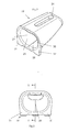
- Fig. 2 an axonometric view of a combustion chamber of the boiler according to Fig. 1
- Fig. 3 a front view of the combustion chamber according to Fig. 2
- Fig. 4 a section through the combustion chamber along the line IV-IV in Fig. 3
- Fig. 5 an axonometric representation of a deflection in the outlet of the combustion chamber
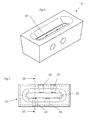
- Fig. 6 an axonometric representation of a fuel gas guide
- Fig. 7 a plan view of the fuel gas duct
- Fig. 8 a section along the line VIII-VIII in Fig. 7 ,
- a frame 1 is provided, in which a water jacket 2 with an inlet 3 and a drain 4 is arranged.
- This water jacket 2 extends over the region near the flue gas outlet 6 and the ceiling region of the frame 1 up to a refill opening 7 for the fuel, in particular wooden logs 8, wherein the opening 7 is closable with a door 5 which is provided with a heat insulation 7 on its inside 'is provided.
- an air chamber 9 is provided below the opening 7, which is bounded by a pre-hung in front of a wall 11 of the frame 1 multi-folded sheet 10.
- the lower wall of the sheet 10 is perforated and allows the access of air.
- the fuel supply 8 is held in a Kraftstoffvorrats- or gasification chamber 12, inter alia, of the inner wall 13 of the Water jacket 2 and frame walls and down through a nozzle block 14 and a surrounding jacket stone 15 is limited, the remaining space between these is covered against the gasification chamber 12.
- the casing brick 15 has passages 16 which produce a connection of the space 17 remaining between the casing brick 15 and the nozzle brick 14 with the air chamber 9.
- the Laval nozzle 18 of the nozzle block 14 connects the carburetor chamber 12 with the interior of a combustion chamber 19, which is arranged in a flame tube 20, whose one end is formed by the wall 13 of the water jacket.
- the wall 13 is penetrated in its sloping rearward region 21 of flue pipes 23, which open into an exhaust gas chamber 22, from which the flue gas outlet 6 leads away.
- flue pipes 23 are flowed through by the hot exhaust gases and heat the water in the water jacket. 2
- the combustion chamber 19 has on its upper side an inlet opening 24 corresponding to the Laval nozzle 18 and an outlet opening 25 facing the front wall of the frame.
- a deflection device in the form of a baffle plate 26 is arranged, which divides the exhaust gas stream and directs it around the combustion chamber 19 against the wall 13 of the water jacket 2.
- a fuel gas guide 27 leads away, which establishes a connection with the gasification chamber 12, which communicates via passages in the wall 11 with the air chamber 9.
- the fuel is supplied with hot exhaust gases and thus brought to outgassing, the resulting fuel gases via the Laval nozzle 18 with the admixture of primary air from the air chamber 9 into the interior of the combustion chamber 19 and burn there.
- the combustion chamber 19 is based on the Fig. 2 to 4 , the deflection device 26 based on the Fig. 5 and the nozzle block 14 on the basis of Fig. 6 to 8 explained in more detail.
- the combustion chamber 19 is made of a monolith of refractory ceramic and has in its upper wall a in the longitudinal direction of the combustion chamber 19 extending inlet opening 24, which corresponds to the outlet opening of the Laval nozzle 18 of the nozzle block 14.
- the interior of the combustion chamber 19 has a rib 28 which extends in the longitudinal direction of the combustion chamber 19 and is formed by the intersection of two partial cross sections 29, 30 with curved boundary lines, so that a "double-bubble" cross-section results.
- the combustion chamber 19 is provided with feet 31, 31 ', 32, with which the combustion chamber 19 rests on the lower boundary of the flame tube 20. This limits the heat removal from the combustion chamber.
- the combustion chamber 19 Since the combustion chamber 19 has a substantially equal wall thickness, the free cross section between the outside of the combustion chamber 19 and the inner wall of the flame tube 20 increases towards the wall 13 of the water jacket 2. This results in a very significant reduction in the flow velocity of the exhaust gases due to the increasing flow cross-section, which precipitate ash.
- the deflection device which passes through the deflection plate 26 (FIG. Fig. 5 ) is formed, has a substantially vertical rib 33, which is formed by an overlap of two substantially Zylindermantelfab Songs corresponding surfaces 34, 35. These surfaces 34, 35 are incorporated in a plate which is held by means of anchor bolts 36 having a heat-insulating layer 38 (FIG. Fig. 1 ) and anchored in a door 37.
- the exiting from the combustion chamber 19 exhaust gases are divided by the rib 33 in two parts and led around the combustion chamber 19, wherein the free cross section between the outside of the combustion chamber 19 and the inner walls of the flame tube 20 increases against the wall 13 of the water jacket 2.
- the nozzle block 14 has, as from the Fig. 6 to 8 can be seen, an elongated inlet opening 39 of an opening, which is designed as a Laval nozzle 18.
- the inlet opening 39 is strongly rounded over its entire circumference.
- the Laval nozzle 18 has near the inlet opening 39 a constriction 40, to which - seen in the flow direction - an expanding region 41 connects, which ends in an outlet opening 42.
Landscapes
- Engineering & Computer Science (AREA)
- Chemical & Material Sciences (AREA)
- Combustion & Propulsion (AREA)
- Mechanical Engineering (AREA)
- General Engineering & Computer Science (AREA)
- Physics & Mathematics (AREA)
- Thermal Sciences (AREA)
Applications Claiming Priority (1)
| Application Number | Priority Date | Filing Date | Title |
|---|---|---|---|
| AT9822010A AT509722B1 (de) | 2010-06-14 | 2010-06-14 | Festbrennstoffkessel |
Publications (1)
| Publication Number | Publication Date |
|---|---|
| EP2395285A2 true EP2395285A2 (fr) | 2011-12-14 |
Family
ID=44510040
Family Applications (1)
| Application Number | Title | Priority Date | Filing Date |
|---|---|---|---|
| EP20110169111 Withdrawn EP2395285A2 (fr) | 2010-06-14 | 2011-06-08 | Chaudière à combustible solide |
Country Status (2)
| Country | Link |
|---|---|
| EP (1) | EP2395285A2 (fr) |
| AT (1) | AT509722B1 (fr) |
Cited By (2)
| Publication number | Priority date | Publication date | Assignee | Title |
|---|---|---|---|---|
| DE102013102361A1 (de) * | 2013-03-08 | 2014-09-11 | Ulrich Brunner GmbH | Ofen mit einem Brennraum und einer Brennkammer |
| DE102024107760A1 (de) * | 2024-03-19 | 2025-09-25 | Schreiber Anlagenbau Gmbh | Schüttgutförderer, Heizungsanlage und Verfahren zum Trocknen eines Festbrennstoffes |
Citations (1)
| Publication number | Priority date | Publication date | Assignee | Title |
|---|---|---|---|---|
| DE102008013891A1 (de) | 2007-03-29 | 2008-10-02 | Windhager Zentralheizung Technik Gmbh | Brennkammer für einen mit Festbrennstoffen beheizbaren Heizkessel |
Family Cites Families (2)
| Publication number | Priority date | Publication date | Assignee | Title |
|---|---|---|---|---|
| FR2687214A1 (fr) * | 1992-02-07 | 1993-08-13 | Dietrich Michel De | Chaudiere a combustible solide, et particulierement chaudiere a bois. |
| KR20030057157A (ko) * | 2001-12-28 | 2003-07-04 | 최진민 | 화목보일러 구조 |
-
2010
- 2010-06-14 AT AT9822010A patent/AT509722B1/de not_active IP Right Cessation
-
2011
- 2011-06-08 EP EP20110169111 patent/EP2395285A2/fr not_active Withdrawn
Patent Citations (1)
| Publication number | Priority date | Publication date | Assignee | Title |
|---|---|---|---|---|
| DE102008013891A1 (de) | 2007-03-29 | 2008-10-02 | Windhager Zentralheizung Technik Gmbh | Brennkammer für einen mit Festbrennstoffen beheizbaren Heizkessel |
Cited By (3)
| Publication number | Priority date | Publication date | Assignee | Title |
|---|---|---|---|---|
| DE102013102361A1 (de) * | 2013-03-08 | 2014-09-11 | Ulrich Brunner GmbH | Ofen mit einem Brennraum und einer Brennkammer |
| DE102013102361B4 (de) * | 2013-03-08 | 2015-01-22 | Ulrich Brunner GmbH | Ofen mit einem Brennraum und einer Brennkammer |
| DE102024107760A1 (de) * | 2024-03-19 | 2025-09-25 | Schreiber Anlagenbau Gmbh | Schüttgutförderer, Heizungsanlage und Verfahren zum Trocknen eines Festbrennstoffes |
Also Published As
| Publication number | Publication date |
|---|---|
| AT509722B1 (de) | 2011-11-15 |
| AT509722A4 (de) | 2011-11-15 |
Similar Documents
| Publication | Publication Date | Title |
|---|---|---|
| EP0708298B1 (fr) | Appareil de chauffage | |
| AT509722B1 (de) | Festbrennstoffkessel | |
| DE4113412C2 (de) | Vorrichtung zur Verbrennung von flüssigem oder gasförmigem Brennstoff für eine Feuerungsanlage | |
| DE561675C (de) | Schalldaempfer fuer Brennkraftmaschinen | |
| EP2196641A1 (fr) | Installation d'échappement pour un moteur à combustion interne | |
| DE2011574A1 (de) | Rotationskolben Brennkraftmaschine | |
| DE29605801U1 (de) | Heizkessel | |
| DE19708229A1 (de) | Dampferzeuger | |
| DE102006009335A1 (de) | Heizkessel, insbesondere für Bio-Festbrennstoffe | |
| DE4115644C1 (en) | Burner in heating boiler - incorporates return gas flues surrounding flame tube | |
| DE102008038763A1 (de) | Festbrennstofffeuerstätte | |
| AT407915B (de) | Luftleitvorrichtung für die zuluft von heizeinrichtungen | |
| DE2743959C2 (fr) | ||
| DE1116336B (de) | Verbrennungsluftzufuehrung fuer Flammrohrkessel-Feuerungen | |
| DE677862C (de) | Rauchverbrennungsvorrichtung fuer Kesselfeuerungen mit die Rauchgase ansaugenden Lufteinlassrohren | |
| AT254460B (de) | Heizkessel mit Flammrohr | |
| DE29800377U1 (de) | Gas-Brennwertkessel | |
| DE8121837U1 (de) | Durchbrandkessel fuer geringwertige brennstoffe wie astholz und stroh | |
| DE3940165C1 (fr) | ||
| DE4425738C2 (de) | Vorrichtung zur Wärmeverschiebung eines Rohgases | |
| DE964099C (de) | Gasheizanlage | |
| DE1075780B (de) | Feuerung mit Nachverbrennungsraum und Zweitluftzufuhr | |
| AT20453B (de) | Schalldämpfer für Explosionskraftmaschinen. | |
| DE2227630C3 (de) | Entspannungskasten für Austrittsgitter von Warmluftheizungen | |
| DE102013102361B4 (de) | Ofen mit einem Brennraum und einer Brennkammer |
Legal Events
| Date | Code | Title | Description |
|---|---|---|---|
| AK | Designated contracting states |
Kind code of ref document: A2 Designated state(s): AL AT BE BG CH CY CZ DE DK EE ES FI FR GB GR HR HU IE IS IT LI LT LU LV MC MK MT NL NO PL PT RO RS SE SI SK SM TR |
|
| AX | Request for extension of the european patent |
Extension state: BA ME |
|
| PUAI | Public reference made under article 153(3) epc to a published international application that has entered the european phase |
Free format text: ORIGINAL CODE: 0009012 |
|
| 17P | Request for examination filed |
Effective date: 20120103 |
|
| STAA | Information on the status of an ep patent application or granted ep patent |
Free format text: STATUS: THE APPLICATION IS DEEMED TO BE WITHDRAWN |
|
| 18D | Application deemed to be withdrawn |
Effective date: 20160105 |