EP2395518B1 - Boîtier destiné au montage de noyaux magnétiques cylindriques, ayants des entrefers, pour des composants inductifs - Google Patents
Boîtier destiné au montage de noyaux magnétiques cylindriques, ayants des entrefers, pour des composants inductifs Download PDFInfo
- Publication number
- EP2395518B1 EP2395518B1 EP10005933.6A EP10005933A EP2395518B1 EP 2395518 B1 EP2395518 B1 EP 2395518B1 EP 10005933 A EP10005933 A EP 10005933A EP 2395518 B1 EP2395518 B1 EP 2395518B1
- Authority
- EP
- European Patent Office
- Prior art keywords
- core
- housing
- ribs
- housing according
- core parts
- Prior art date
- Legal status (The legal status is an assumption and is not a legal conclusion. Google has not performed a legal analysis and makes no representation as to the accuracy of the status listed.)
- Active
Links
Images











Classifications
-
- H—ELECTRICITY
- H01—ELECTRIC ELEMENTS
- H01F—MAGNETS; INDUCTANCES; TRANSFORMERS; SELECTION OF MATERIALS FOR THEIR MAGNETIC PROPERTIES
- H01F3/00—Cores, Yokes, or armatures
- H01F3/10—Composite arrangements of magnetic circuits
- H01F3/14—Constrictions; Gaps, e.g. air-gaps
-
- H—ELECTRICITY
- H01—ELECTRIC ELEMENTS
- H01F—MAGNETS; INDUCTANCES; TRANSFORMERS; SELECTION OF MATERIALS FOR THEIR MAGNETIC PROPERTIES
- H01F27/00—Details of transformers or inductances, in general
- H01F27/02—Casings
- H01F27/022—Encapsulation
-
- H—ELECTRICITY
- H01—ELECTRIC ELEMENTS
- H01F—MAGNETS; INDUCTANCES; TRANSFORMERS; SELECTION OF MATERIALS FOR THEIR MAGNETIC PROPERTIES
- H01F27/00—Details of transformers or inductances, in general
- H01F27/24—Magnetic cores
- H01F27/26—Fastening parts of the core together; Fastening or mounting the core on casing or support
- H01F27/263—Fastening parts of the core together
-
- H—ELECTRICITY
- H01—ELECTRIC ELEMENTS
- H01F—MAGNETS; INDUCTANCES; TRANSFORMERS; SELECTION OF MATERIALS FOR THEIR MAGNETIC PROPERTIES
- H01F41/00—Apparatus or processes specially adapted for manufacturing or assembling magnets, inductances or transformers; Apparatus or processes specially adapted for manufacturing materials characterised by their magnetic properties
- H01F41/005—Impregnating or encapsulating
Definitions
- the invention relates to a housing for the construction of air gap split magnetic core columns for inductive components, in particular for chokes, transformers, transformers, converters, and similar inductive components.
- bobbin or insulating cylinder are produced for example by injection molding or extrusion molding, wherein the bobbin is formed as a hollow cylinder, in which, for example, magnetic cores are used.
- wound coil body which are formed into insulating cylinders.
- cores for chokes are formed, for example, columnar and consist of one or more bonded together core parts and core disks, which are separated by so-called "air gaps", z. B. in the form of spacers made of insulating material, are separated from each other.
- these core columns were made of z.
- the purpose of these air gaps is to design and optimize the electromagnetic properties of the choke coils, so that the highest possible amounts of magnetic energy are stored in the air gap spaces, but the stray fields outside the air gaps or the insides of the windings are still kept low.
- the "air gap spaces" to serve individual core parts or discs, mechanically with each other To connect, in particular to bridge the so-called air gaps with adhesive-coated discs.
- the EP 0 848 391 A1 a housing for the construction of separate by air gaps magnetic core columns for inductive components, which has an inner space bounding inner lateral surfaces on which a plurality of radially projecting into the interior ribs or fin projections are arranged.
- the interior is subdivided by the ribs or rib projections into several juxtaposed chambers for receiving core disks or core parts of the magnetic core column.
- the ribs are arranged rigidly and do not allow adjustment of the distances of the core disks or core parts in order to adjust, for example, the inductance of the inductive component to be built up.
- the invention was u. a. the task of designing a housing for the construction of magnetic core columns so that inductive components can be realized with multiple-part, separated by air gaps core disks or core parts, easier and less expensive and adjustable.
- the housing is designed as a so-called grid housing with grid half shells, grid or even a grid casting.
- the grid housing forms chambers for receiving core disks or core parts, which together form the magnetic core.
- z. B. with a corresponding outer housing or a novel tub housing, two or more of these grid housing can be assembled into a complex inductive component.
- the grid housing is used to build a simple inductive component with a magnetic core.
- a corresponding outer housing or tub housing two or more of these grid housing can be combined to form a larger inductive component.
- the grid shells, grid strips, grid casings according to the invention comprise at least one elongated hollow body, on the inner lateral surfaces of which a plurality of ribs, nubs or other configurations, which project radially into the interior space, e.g. Grooves with intermediate layers, are arranged, wherein the part-inner spaces are divided by ribs, corrugations, even axially bendable knobs, or grooves quasi into several to many axially juxtaposed chambers for receiving core disks and core parts.
- the hollow body consists of two axially divided grid half-shells, each core part or each core disk being characterized by at least one circularly arranged rib or knob arrangement or other configurations, such as e.g. Grooves in which the core disks or core parts are held, is separated from an adjacent core disk or a core part.
- the chambers are formed either by the formed on the inner circumferential surfaces of the half-shells, radially projecting into the interior ribs or rib projections or nubs, or by formed in the inner wall of the half-shells grooves with intermediate layers.
- the ribs or rib projections or nubs or the intermediate layers at least partially define the required air gaps between the core disks or core parts.
- the half-shells are constructed symmetrically, d. H.
- semi-cylindrical, rectangular or other cavities are formed in the interior of the two halves of the grid, in which core disks or differently shaped partial cores can be accommodated in the manner necessary for the respective type of inductive component.
- An attached hollow body of z. B. two half-shells forms several or many partial grid spaces, for example, cylindrical chambers but also other geometric, z.
- the disks or core parts are inserted into the chambers of the first half-raster half-shell and closed by the second half-raster shell. This eliminates the need for stacking, in which, for example, core disks had to be glued one atop the other.
- half shells according to the invention can also be used, for example, for the packaging of core disks or other core parts.
- the individual discs or core parts can be inserted at the manufacturer in grid half shells. They are protected for transport in the same quality as before.
- the remaining hollows can be filled with low-viscosity adhesive resin.
- standard resins can also be used if the core columns are evacuated after filling with more viscous resin or another filling compound.
- yokes with thin resins but also standard Aus shellmassen is filled.
- Vergussmassen preferably with lower coefficients of thermal expansion. The penetration of the potting compounds in the cavities to be filled can be supported by evacuating the cavities.
- the following described embodiments of the invention relate e.g. on housings for the construction of coils for chokes whose magnetic circuits consist of largely standardized soft magnetic materials or ferrite materials, such as core disks and yokes. Furthermore, the invention relates to packages for the construction of coils for chokes whose magnetic circuits are composed of yokes and core parts of non-standard magnetic materials, d. H. where optimizations have been made to the yokes and core parts, washers and outer casings to better capture the core ideas and secondary innovations.
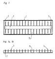
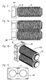
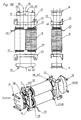
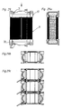
- the Figures 1 and 1a show a plan view and a section through a so-called grid half shell 1 a of the housing 1.
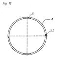
- the half-raster shell 1a is formed in the form of a thin-walled half-cylinder and has a continuous axially-flat recess 2, see. also FIG. 18 , Left and right of the recess 2 are z.
- the individual chambers are in the longitudinal direction of the grid half shell Fig. 1a arranged one behind the other.
- the ribs / lugs 3, 3a or grooves on the inner circumference of the half-raster shell 1a are arranged, preferably in pairs in the form of, for example, circular segments.
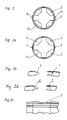
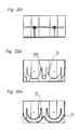
- FIG. 2a shows a section through the screen half-shell 1a in the region of the rigid ribs 3.
- the ribs 3, 4 are each separated by the recess 2 in the form of a flat circular groove and preferably formed in pairs.
- FIG. 2b shows an isometric view of a grid half shell 1a, 1b with rigid ribs 3 and until shearing bendable ribs 4 or nubs 4a in Fig. 5c ,
- the bendable or compressible ribs or nubs 4, 4a are preferably arranged on the respective outer parts of the half-shells 1 a, 1 b.
- each half-raster 1a has a continuous frame 6 in Fig. 2b, c , And a continuous groove 7, with which this can be connected to another identical constructed half-scale shell 1 b to a complete cylindrical housing 1.
- FIG. 5e shows reduced air gaps 37 in the tensioned state.
- FIGS 5g (1), (2) show as an alternative to the above an elastic intermediate layer 78, 79, 80, in the form of a compressible and extensible thin plate, which can be used instead of or in addition to bendable ribs 4 or nubs 4a, for example according to Figure 19d ,
- FIGS. 3 and 3a show a view or a section through a half-raster shell 1 a with inserted core disks 9 as a magnetic core column.
- the screen half-shell 1a comprises ribs 3, 4 or rib projections, nubs 4a, cf. Fig. 5 ff.
- the core parts for. B. in the form of core disks 9, inserted, wherein the plus-tolerance diameter of the core disks 9 are smaller than that Inner diameter of two together halftone shells 1 a, 1 b or hinge-closed half-shells Fig. 5h to 5k ,
- the inner diameter of the joined grid half shells is reduced Fig. 5c , and forms a centering and retaining collar for outer core disks 57, ie the two outermost core disks sit backlash-free or under slight compression stress in the unshifted half-shell 1 a, 1 b.
- the end portions of the grid half-shell chambers are not compressed because the core disks 9 are absolutely rigid and sit without play in the associated chambers, resulting in a good frictional connection core column outer housing. Otherwise, the "thicknesses" or “heights" of the core disks 9 are slightly smaller than the minimum diameter and axial dimensions of the chambers, ie the distance between ribs 3, rib projections 3a and nubs 4th
- the half-raster shell 1a with a second half-raster shell 1 b closed or analogous to Figures 5h or 5k folded by means of a bending hinge 52. This eliminates the need for conventional stacking operations where core disks / parts need to be stacked and glued together piece by piece.
- the described technique of inserting the core parts 9 in the half-shells 1a, b is much more efficient and precise than the stacking of individual core disks or core parts, even if stacking techniques are automated or semi-automated or were.
- the effort for merging the core parts 9 is reduced to simple and short-term insertion operations of the core parts 9 into the chambers 76 of the half-shell 1 a and the adhesive bonding of the second half-shell 1 b, and Fig. 5d, 5e considerably.
- FIG. 4 shows z. B. the joined configuration consisting of the half-shells 1a and 1b.
- the FIG. 4a shows the assembled housing 1 with inserted core parts.
- the Figures 5 . 5a to 5g show in detail cross sections of the assembly of half-shells 1 a and 1 b and Fig. 19 ff.
- Each half-raster shell 1a, 1b comprises on the inner circumference distributed ribs 3 ( Fig. 5a ) or rib projections 3a (FIG. Fig. 5b ), as well as bendable ribs 4 ( Fig. 5 ) or nubs 4a ( Fig. 5c ), which form the intermediate spaces, ie chambers, for receiving the core parts 9.
- FIG. 2b shows the on the longitudinal side of the half-shells 1 b 1 a extending frames 6 or 6 'or grooves 7 or 7a, which allow an accurate and electrically secure assembly and bonding of the two halves halves 1 a, 1 b.
- FIGS. 2b and 2c can show frames 6, 6 'and grooves 7, 7' have both trapezoidal cross-sections and rectangular cross-sections.
- the FIGS. 5 to 5k show that on the long side generally voltage-resistant joining grooves are provided.
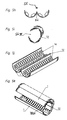
- hinge half shells Fig. 5h to Fig. 5k manufacture are connected to one another on one of their longitudinal sides with a bending hinge 52 and can be folded together by means of this bending hinge 52.
- one side of the double half-raster half-shell (FIG. 5j) is fitted with core disks and the unfitted half-raster half-shell is folded onto the filled shell.
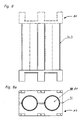
- FIGS. 6 to 6b and 27 and exploded view Fig. 28 For example, show outer housing 10, 43, which can be connected to grid half-shell core columns. These outer housing 10, 43 consist z. B. from a two-hole base plate, mounting bars and version Fig. 27 in addition from a Umrandungskragen, which for specially shaped yokes and the admission of casting resin Fig. 28 is designed.
- the base plate of the outer housing 10, 43 includes holes 11 with undercuts 12, so that the core columns can be locked non-positively and shear-resistant on the outer housing 10, 43.
- the openings 11 with the undercuts 12 are reduced with clamping screws 13 in their diameters by the clamping screw 13 is tightened.
- the undercuts 12 of the holes 11 of the outer housing in Fig. 25 . 28 engage in the grooves 5 of the housing 1 and are clamped by clamping screws 13 in the grooves 5.
- the remaining gap 14 is sealed with a seal 15 so that the connections between the housing 1 with core columns, the outer housings 10 and held on / in the outer housing yokes 17 is closed and interfere with the pouring of the cavities no leaks the potting process.
- FIG. 9 shows a single winding 16, as they are applied to the housing 1.
- FIG. 9a shows a plan view of a single winding. It forms between the housings 1 via the interface outer housing 10, a compound which z. B. by automatic bonding with the structural cast can be made even more stable ( Figs. 7a-7e ).
- the equipped with yokes 17 outer housing 10 and associated housing 1 are filled after assembly with low-viscosity filling and / or adhesive resin. In this case, the difference volume between the interior of the half-shells 1 minus the sum of the volumes of the core parts 9 plus Jochklebung is filled.
- the casting compound flows through the axially sealed half shells Fig. 25 and 28 and fills from the inner yoke 40, outer housing 10 via the individual core disks 9 to the filling space between the "upper" outer housing 43 and yoke 40, where no seal is placed on. At the same time escapes through the resin displaced air from the minimum voids of the housing 1 with windings 16 and the adhesive and Guss vom between outer housings 10 and yokes 17.
- a casting material usually low viscosity casting, polyester or PU resin, etc. is used ,
- FIGS. 4, 4a, 4b show how core disks 9 or core parts of a core column in the grid half shell 1 a are inserted.
- the core disks or core parts 9 have in the Usually a slight axial play in their respective chambers, because the ribs 3 and 4 are formed thinner than the intended and calculated air gap between the discs or core parts 9. Any tolerances of the core parts 9 are easily compensated.
- the second halftone half shell 1 b is closed by means of the core halves 9 filled with the first half-shell 1a. Alternatively, however, non-adhesive may be introduced into the groove 7 or to the frame 6 of the half-shells.
- FIG. 2, 2a . 5-5k show, in addition to the rigid ribs 3, 3a, axially movable nubs 4a (FIG. Fig. 5b ) and alternatively or additionally compressible intermediate layers 80 (FIG. Fig. 5g ), which has a larger core disk reset option 5e or 5d z. B. have inaccurate adjustment.
- the bendable nubs 4a ( Fig. 5b, 5c ) and also the compressible intermediate layers 80 (FIG. Fig. 5g ) at the ends of the half shells 1a, core columns, are needed because the core columns have many core disks or core parts 9 that are subject to dimensional tolerances.
- the lengths of the half shells 1a and 1b are generally smaller than the lengths of the sequentially arranged core disks 9 plus the sum of the air gaps. Ie. the frontal, outer core disks or core parts 9 protrude slightly with a projection 38, 39 from the closed half-shells 1a, 1b (FIG. FIGS. 5d, 5e ), out. This is necessary to obtain a force 53, 54, Fig. 5d, 5e ) to be able to exert on the outer core disks 9 or core parts, so that the core disk distance plus / minus adjusted and thus the length of the core column can be adjusted, but on the other hand, so that on the surfaces of the outermost core disks or core parts and the yokes 17 and 40 ( Fig. 28 ) can be placed almost without a column.
- the number of molded parts of a throttle is according to the above 6. This number can be halved if z. B. on an outer side of the half shells horizontally divided outer housing ( Fig. 8, 8a 5, 5d ) are integrated by injection molding or two half-shells with a connecting hinge hinge 52 are designed to be foldable.
- FIG. 7 shows an intermediate assembly with an outer housing 10 before the complete assembly with winding 16 and an inserted into the outer housing 10 yoke 17 which is mounted on the same housings 1.
- FIGS. 7 and 7a show the arrangement of the yoke 17 in the two joined housings 1. Depending on a winding 16 is respectively arranged on the housings 1. How to get out of the FIGS. 7d and 7e detects, bridge connections 19 are arranged on the revolving collar or webs of the outer housing 19, which close the frictional connection in the outer housing, surrounding the yoke 17 and secure after curing of the mecanicvergusses.
- the "shrinkage" of the potting compound can also be preceded by correcting, in that the difference potting compound liquid - later hardened, is taken into account, FIGS. 5d , e.
- a throttle stacking function can be realized with the outer housing.
- only defined tapping screws are required in order to set up and screw one throttle at the next lower one.
- second installation levels are z. B. possible in inverters.
- both metal and plastic plates can be easily attached.
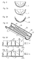
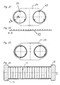
- core column strips Fig. 22-24 possible. That is, the core disks 9 or parts with, for example, three or four grid strips 69 before insertion into an injection mold Fig. 21, 23 fixed by the brackets 70 and adjusted according to the described method, also encapsulated or cast around.
- FIG. 24
- z. B. is the largest and dimensioning cross-section in the middle of a yoke 40, because only there is the maximum magnetic flux.
- All cross sections outside the central region of the yoke 40 can be reduced to half - left / right of the center or less large cross-section. Ie. all cross sections going from the central area to the outside Fig. 26 , Numerals 65, 64, 63 are adapted to the reduced magnetic fluxes. This creates space for the placement of terminals, contact fittings, winding bridges, and integrated foot structures of the chokes Fig. 27 . 28 and the adjusting devices for the yokes and the throttles in total. Thus, with better flow / cross section quotients, up to 30% of magnetic material is saved in the Jochen.
- Fig. 29 conceptually, minimum capacitances between the windings and ground are achieved, which is very advantageous for use in inverters because the minimized capacitances reduce the switching losses of inverters.
- Adhesive breaks between the core disks 9, Fig. 12 . 14 . 15 . 24 . 25 . 29 and core parts are virtually excluded. Nevertheless, if an adhesive break between core disks 9 occur, this has no consequences, because the halves of the grid keep the core columns connected without dimensional changes.
- FIG. 13 shows an alternative to the previous embodiments, a complete manufacturing form, consisting of a lower part 25 and a top 26.
- 26 can be made completely one or more parts injection-molded or cast or pressure-gelled core columns.
- two retaining pins 27 are arranged in the lower part 25 of the manufacturing mold per core part.
- the core parts 9 can be fixed in the bottom part 25 exactly with a defined distance (air gap).
- the upper part 26 of the manufacturing form has per core disk or core part 9 a fixing pin 28.
- Three fixing pins 27, 28 for each core part 9 are sufficient to fix the entire arrangement of core disks 9 in the production form before the casting process.
- core disks or core parts 9 are in the form of receptacles for enclosing the core disks or for sealing at the ends of the core columns.
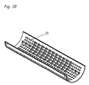
- the pin assemblies can be dispensed with in a mold or mold when, for example, halftone shells 72 are used with a thin, apertured sheath.
- the hole pattern in the shell of the half-raster shell 72 allow the unhindered entry of the spray or casting compound into the gaps between the core disks or core parts inserted in the half-rake shell, as well as the closure of the insulating cylinder part around the core disks or parts.
- core disks / core parts 9 manufacturing forms according to the Fig. 21-24 be like the Figures 12 or 13 filled with spray or potting compound. After solidification of the spray or potting compound to obtain a thin coated core column.
- the core disks 9 are separated by Rasternoppen or discs and injection molding compound filled air gaps.
- embossed mounting grooves are used for attachment to an outer housing 10th
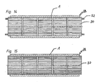
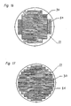
- FIGS. 14 to 17 Shown in housings 1, consisting of upper part and lower part, not round core parts 30, 31 are added.
- the show FIGS. 14-17 Housing in which cuboid or cube-shaped core parts are included.
- clamping screws 32, Fig. 14 in the claddings of the core columns Fig. 14, 15th are introduced, which can serve for the attachment of outer housings, yokes or bearing plates or flanges.
- FIG. 16 shows configurations of such a molded or cast housing 1 in which rectangular core parts 30, 31 are arranged.
- the core parts have different dimensions and thicknesses to best fill the cross sections of the core columns.
- FIG. 16 a cross section of a core column, it can be seen that the total cross section of a square core member 30 and distributed on the sides, four rectangular side core parts 31 join.
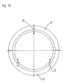
- FIG. 17 shows a staggered core configuration.
- core parts 30, 31 are arranged, the differentiated in their dimensions -Folienumble- different and thus use the round cross-section of the housing 1 and fill.
- the core columns of core parts 30, 31 are separated from each other by corresponding intermediate layers or rib projections, which then form the air gaps.
- FIGS. 19, 19a to 19d show halftone shells in different views and the composite housing according to FIGS. 19c and 19d , To fill the housing 1 with casting compound recesses 2 are in turn arranged on the inner wall as in the half-shells 1 a, 1 b.
- FIG. 30 This is in the Figures 30 and 31 shown.
- the tub housing 73 has axial longitudinal configurations in the form of, for example, longitudinal recesses 74, as shown FIG. 31 can be seen correspondingly elongated receptacles for two wound core columns, Fig. 31 ,
- the core columns can be placed in the spaces formed by the longitudinal troughs 74 with the yokes 17 placed in the shell ends of the trough.
- the tub housing 73 After the tub housing 73 is filled with core columns and yokes 17, it can be filled with potting compound, so that there is a partially cast in the tub housing 73 throttle component 75.
- throttle versions and versions allow a significant manufacturing technology, qualitative, also "electrical" progress for sine-chokes, especially consisting of ferrite disks and yokes made of ferrite material. Also analogous application with new core materials are possible.
Landscapes
- Engineering & Computer Science (AREA)
- Power Engineering (AREA)
- Manufacturing & Machinery (AREA)
- Chemical & Material Sciences (AREA)
- Composite Materials (AREA)
- Coils Or Transformers For Communication (AREA)
Claims (17)
- Boîtier (1) pour le montage de noyaux magnétiques cylindriques, séparés par un entrefer, pour composants inductifs, qui présente des surfaces d'enveloppe intérieures qui délimitent un espace intérieur et sur lesquelles sont disposées plusieurs nervures ou saillies en forme de nervures ou bosses (3 ; 3a ; 4 ; 4a) ou rainures (89) avec des couches intermédiaires (78-80), qui dépassent radialement dans l'espace intérieur, étant précisé que l'espace intérieur est divisé par les nervures ou saillies en forme de nervures ou bosses (3 ; 3a ; 4 ; 4a) ou par les rainures (89) avec les couches intermédiaires (78-80 en plusieurs chambres alignées (76) destinées à recevoir des plaques ou éléments de noyau (9 ; 30, 31) du noyau magnétique cylindrique , caractérisé
en ce qu'il est prévu aussi bien des nervures ou saillies en forme de nervures (3, 3a) ou des rainures (89) rigides que des nervures ou bosses (4, 4a) aptes à être pliées, aptes à être cisaillées en supplément dans le sens axial ou flexibles axialement, ou des couches intermédiaires (8) aptes à être comprimées. - Boîtier selon la revendication 1, caractérisé en ce que le boîtier (1) se compose d'au moins deux demi-coques à trame (1a ; 1b) séparées axialement.
- Boîtier selon l'une des revendications 1 ou 2, caractérisé en ce que chaque plaque ou élément de noyau (9 ; 30, 31) est séparé d'une plaque ou élément de noyau voisin par au moins une nervure ou saillie en forme de nervure (3 ; 3a ; 4 ; 4a) ou une rainure avec une couche intermédiaire, et cette nervure ou partie en forme de nervure (3 ; 3a ; 4 ; 4a) ou la couche intermédiaire forme une partie d'un entrefer prédéfini entre les éléments de noyau (9 ; 30, 31) voisins.
- Boîtier selon la revendication 1, caractérisé en ce que le boîtier (1) se compose d'une seule pièce, dont l'espace intérieur de forme allongée, axialement, est divisé par les nervures (3, 3a ; 4, 4a) en plusieurs chambres alignées axialement, étant précisé que les nervures (3, 3a ; 4, 4a) forment une partie des entrefers prédéfinis entre les éléments de noyau (9 ; 30, 31).
- Boîtier selon l'une des revendications 1 à 4, caractérisé en ce que l'épaisseur des nervures ou des saillies en forme de nervures (3, 3a ; 4, 4a) ou des couches intermédiaires est de préférence inférieure à l'épaisseur des entrefers prédéfinis entre les lames ou éléments de noyau (9, 30, 31).
- Boîtier selon l'une des revendications 1 à 5, caractérisé en ce que les nervures ou saillies en forme de nervures (3, 3a ; 4, 4a) ont des épaisseurs différentes.
- Boîtier selon l'une des revendications 1 à 6, caractérisé en ce que les nervures ou bosses (4, 4a) aptes à être pliées, aptes à être cisaillées ou flexibles axialement sont disposées dans l'espace intérieur des demi-coques à trame (1a, 1b) dans des évidements creusés, sur le diamètre intérieur.
- Boîtier selon l'une des revendications 1 à 8, caractérisé en ce que les plaques ou éléments de noyau (9) frontaux situés à l'extérieur sont maintenus sans jeu dans leurs chambres (76) à l'aide de collets intérieurs et servent d'appui rigide lors du montage, avant le scellement.
- Boîtier selon l'une des revendications 1 à 9, caractérisé en ce que les plaques ou éléments de noyau (9 ; 30, 31) sont maintenus en étant mobiles dans les chambres (76) du boîtier (1) et sont fixés de manière rigide et inamovible grâce au versement d'une masse de scellement dans les chambres (76).
- Boîtier selon l'une des revendications 1 à 10, caractérisé en ce que les éléments de noyau (9) placés dans le boîtier ont principalement la forme de plaques.
- Boîtier selon l'une des revendications 1 à 11, caractérisé en ce que les plaques de noyau (30 ; 31) sont parallélipipédiques ou cubiques.
- Boîtier selon l'une des revendications 1 à 12, caractérisé en ce que les plaques ou éléments de noyau (9, 30, 31) sont fixés temporairement dans des moules d'injection ou de coulée avec des tiges et sont enrobés d'une masse d'injection ou de scellement, étant précisé que la masse d'injection ou de scellement forme le boîtier (1) et les nervures (3, 3a, 4, 4a).
- Boîtier selon l'une des revendications 1 à 13, caractérisé en ce que les plaques ou éléments de noyau (9) sont maintenus avec des coques à trame perforées dans un moule d'injection ou de coulée, étant précisé que les cavités entre les plaques ou éléments de noyau et l'élément cylindrique sont remplis d'une masse d'injection ou de scellement.
- Boîtier selon l'une des revendications 1 à 14, caractérisé en ce que les plaques ou éléments de noyau (9) sont maintenus avec des barrettes à trame dans un moule d'injection ou de coulée, étant précisé que les cavités entre les plaques ou éléments de noyau et l'élément cylindrique sont remplis d'une masse d'injection ou de scellement.
- Boîtier selon l'une des revendications 1 à 15, caractérisé en ce que les plaques ou éléments de noyau (9) sont maintenus avec des barrettes à trame dans un moule d'injection ou de coulée dans des rainures, étant précisé que les cavités entre les plaques ou éléments de noyau et l'élément cylindrique sont remplis d'une masse d'injection ou de scellement.
- Boîtier selon l'une des revendications 1 à 16, caractérisé en ce que les chambres individuelles (76) sont reliées par au moins deux creux ou conduits (2) qui s'étendent dans le sens axial dans la paroi du boîtier (1).
- Boîtier selon l'une des revendications 1 à 17, caractérisé en ce qu'il est prévu aux extrémités du boîtier (1) des dispositifs et des rainures (5) pour la fixation de boîtiers extérieurs (10).
Priority Applications (4)
| Application Number | Priority Date | Filing Date | Title |
|---|---|---|---|
| EP10005933.6A EP2395518B8 (fr) | 2010-06-09 | 2010-06-09 | Boîtier destiné au montage de noyaux magnétiques cylindriques, ayants des entrefers, pour des composants inductifs |
| ES10005933T ES2432492T3 (es) | 2010-06-09 | 2010-06-09 | Carcasa para la construcción de núcleos magnéticos cilíndricos separados por el entrehierro para componentes inductivos |
| DK10005933.6T DK2395518T3 (da) | 2010-06-09 | 2010-06-09 | Hus til konstruktion af luftspalteseparerede cylindriske magnetiske kerner til induktive komponenter |
| PL10005933T PL2395518T3 (pl) | 2010-06-09 | 2010-06-09 | Obudowa do budowy magnetycznych kolumn rdzeniowych rozdzielonych szczeliną powietrzną do komponentów indukcyjnych |
Applications Claiming Priority (1)
| Application Number | Priority Date | Filing Date | Title |
|---|---|---|---|
| EP10005933.6A EP2395518B8 (fr) | 2010-06-09 | 2010-06-09 | Boîtier destiné au montage de noyaux magnétiques cylindriques, ayants des entrefers, pour des composants inductifs |
Publications (3)
| Publication Number | Publication Date |
|---|---|
| EP2395518A1 EP2395518A1 (fr) | 2011-12-14 |
| EP2395518B1 true EP2395518B1 (fr) | 2013-08-14 |
| EP2395518B8 EP2395518B8 (fr) | 2014-01-08 |
Family
ID=43478284
Family Applications (1)
| Application Number | Title | Priority Date | Filing Date |
|---|---|---|---|
| EP10005933.6A Active EP2395518B8 (fr) | 2010-06-09 | 2010-06-09 | Boîtier destiné au montage de noyaux magnétiques cylindriques, ayants des entrefers, pour des composants inductifs |
Country Status (4)
| Country | Link |
|---|---|
| EP (1) | EP2395518B8 (fr) |
| DK (1) | DK2395518T3 (fr) |
| ES (1) | ES2432492T3 (fr) |
| PL (1) | PL2395518T3 (fr) |
Families Citing this family (3)
| Publication number | Priority date | Publication date | Assignee | Title |
|---|---|---|---|---|
| CN105913999B (zh) * | 2014-12-05 | 2017-12-19 | 海宁联丰东进电子有限公司 | 一种uc型电源滤波器结构 |
| DE102016216499B4 (de) * | 2016-09-01 | 2018-04-19 | Siemens Aktiengesellschaft | Spannungswandlereinheit mit einem Aktivteilgehäuse |
| CN117884829B (zh) * | 2024-01-25 | 2024-07-26 | 宁波森汇达机电制造有限公司 | 一种电储能柜自动焊接机构 |
Family Cites Families (4)
| Publication number | Priority date | Publication date | Assignee | Title |
|---|---|---|---|---|
| CH240899A (de) * | 1942-09-05 | 1946-01-31 | Philips Nv | Hochfrequenzspule. |
| AU4536197A (en) * | 1996-12-12 | 1998-06-25 | J.E. Thomas Specialties Limited | RF power coil or choke for separating RF and AC in a CATV or similar system |
| ATE497627T1 (de) | 2003-07-23 | 2011-02-15 | Sts Spezial Transformatoren Stockach Gmbh & Co | Ferritkern für ein induktivitätsbauteil |
| US20090237193A1 (en) * | 2008-03-20 | 2009-09-24 | Timothy Craig Wedley | Multi-core inductive device and method of manufacturing |
-
2010
- 2010-06-09 PL PL10005933T patent/PL2395518T3/pl unknown
- 2010-06-09 EP EP10005933.6A patent/EP2395518B8/fr active Active
- 2010-06-09 DK DK10005933.6T patent/DK2395518T3/da active
- 2010-06-09 ES ES10005933T patent/ES2432492T3/es active Active
Also Published As
| Publication number | Publication date |
|---|---|
| PL2395518T3 (pl) | 2014-05-30 |
| ES2432492T3 (es) | 2013-12-03 |
| ES2432492T8 (es) | 2013-12-26 |
| EP2395518B8 (fr) | 2014-01-08 |
| EP2395518A1 (fr) | 2011-12-14 |
| DK2395518T3 (da) | 2013-11-11 |
Similar Documents
| Publication | Publication Date | Title |
|---|---|---|
| EP2908320B1 (fr) | Transformateur avec structure d'isolation et procédé de fabrication d'un transformateur avec structure d'isolation | |
| WO2019115043A1 (fr) | Rotor et procédé de fabrication d'un rotor | |
| EP0102513A1 (fr) | Transformateur à sec avec enroulements fondus dans une résine de coulée | |
| EP3857682A1 (fr) | Dispositif de connexion conçu pour un moteur électrique | |
| DE3234098A1 (de) | Verfahren zur herstellung in giessharz eingebetteter wicklungen fuer transformatoren | |
| WO2015004121A1 (fr) | Procédé de coulée permettant de produire une gaine de protection autour d'un parafoudre et moule pour ledit procédé | |
| EP2395518B1 (fr) | Boîtier destiné au montage de noyaux magnétiques cylindriques, ayants des entrefers, pour des composants inductifs | |
| DE102012013480A1 (de) | Baugruppe und Verfahren zur Herstellung einer Baugruppe | |
| EP3374145A1 (fr) | Dispositif de moulage d'objets par injection et sur prisonnier | |
| WO2019180099A1 (fr) | Module magnétique | |
| EP2395517B1 (fr) | Composant inductif doté d'un noyau magnétique | |
| EP3723196B1 (fr) | Antenne | |
| EP3129995A1 (fr) | Structure d'enroulement et procédé de fabrication de la structure d'enroulement | |
| EP0557549B1 (fr) | Transformateur à noyau annulaire | |
| DE2447155A1 (de) | Elektromotor und verfahren zu seiner herstellung | |
| EP2549622A1 (fr) | Machine électrique dotée d'un élément actif à dents évasées | |
| DE102013001916A1 (de) | Elektromotor | |
| WO2011086028A1 (fr) | Chambre de coupure pour un disjoncteur ainsi que disjoncteur équipé d'une chambre de coupure | |
| WO2019115042A1 (fr) | Rotor ainsi que procédé de fabrication d'un rotor | |
| AT508741B1 (de) | Spritzguss-isolator | |
| WO2017121568A1 (fr) | Ensemble bobinage avec pied pour scellement vertical | |
| WO2013020859A1 (fr) | Enroulement et procédé de fabrication d'un enroulement à canal de refroidissement | |
| EP0556756B1 (fr) | Capuchon isolant pour les branchements ou connexions des barres d'enroulement de machines électriques | |
| EP3161836B1 (fr) | Unité d'empilage pour réception des plaques noyaux pour composant inductif | |
| DE3920732C2 (de) | Elektrisches Induktionsgerät |
Legal Events
| Date | Code | Title | Description |
|---|---|---|---|
| AK | Designated contracting states |
Kind code of ref document: A1 Designated state(s): AL AT BE BG CH CY CZ DE DK EE ES FI FR GB GR HR HU IE IS IT LI LT LU LV MC MK MT NL NO PL PT RO SE SI SK SM TR |
|
| AX | Request for extension of the european patent |
Extension state: BA ME RS |
|
| PUAI | Public reference made under article 153(3) epc to a published international application that has entered the european phase |
Free format text: ORIGINAL CODE: 0009012 |
|
| 17P | Request for examination filed |
Effective date: 20120208 |
|
| 17Q | First examination report despatched |
Effective date: 20120725 |
|
| GRAP | Despatch of communication of intention to grant a patent |
Free format text: ORIGINAL CODE: EPIDOSNIGR1 |
|
| GRAS | Grant fee paid |
Free format text: ORIGINAL CODE: EPIDOSNIGR3 |
|
| GRAA | (expected) grant |
Free format text: ORIGINAL CODE: 0009210 |
|
| AK | Designated contracting states |
Kind code of ref document: B1 Designated state(s): AL AT BE BG CH CY CZ DE DK EE ES FI FR GB GR HR HU IE IS IT LI LT LU LV MC MK MT NL NO PL PT RO SE SI SK SM TR |
|
| REG | Reference to a national code |
Ref country code: GB Ref legal event code: FG4D Free format text: NOT ENGLISH |
|
| REG | Reference to a national code |
Ref country code: AT Ref legal event code: REF Ref document number: 627253 Country of ref document: AT Kind code of ref document: T Effective date: 20130815 Ref country code: CH Ref legal event code: EP |
|
| REG | Reference to a national code |
Ref country code: IE Ref legal event code: FG4D Free format text: LANGUAGE OF EP DOCUMENT: GERMAN |
|
| REG | Reference to a national code |
Ref country code: CH Ref legal event code: NV Representative=s name: LUCHS AND PARTNER AG PATENTANWAELTE, CH |
|
| REG | Reference to a national code |
Ref country code: DE Ref legal event code: R096 Ref document number: 502010004314 Country of ref document: DE Effective date: 20131010 |
|
| REG | Reference to a national code |
Ref country code: RO Ref legal event code: EPE |
|
| REG | Reference to a national code |
Ref country code: DK Ref legal event code: T3 Effective date: 20131104 |
|
| REG | Reference to a national code |
Ref country code: SE Ref legal event code: TRGR |
|
| REG | Reference to a national code |
Ref country code: NL Ref legal event code: VDEP Effective date: 20130814 |
|
| REG | Reference to a national code |
Ref country code: LT Ref legal event code: MG4D |
|
| PG25 | Lapsed in a contracting state [announced via postgrant information from national office to epo] |
Ref country code: NO Free format text: LAPSE BECAUSE OF FAILURE TO SUBMIT A TRANSLATION OF THE DESCRIPTION OR TO PAY THE FEE WITHIN THE PRESCRIBED TIME-LIMIT Effective date: 20131114 Ref country code: CY Free format text: LAPSE BECAUSE OF FAILURE TO SUBMIT A TRANSLATION OF THE DESCRIPTION OR TO PAY THE FEE WITHIN THE PRESCRIBED TIME-LIMIT Effective date: 20130731 Ref country code: LT Free format text: LAPSE BECAUSE OF FAILURE TO SUBMIT A TRANSLATION OF THE DESCRIPTION OR TO PAY THE FEE WITHIN THE PRESCRIBED TIME-LIMIT Effective date: 20130814 Ref country code: PT Free format text: LAPSE BECAUSE OF FAILURE TO SUBMIT A TRANSLATION OF THE DESCRIPTION OR TO PAY THE FEE WITHIN THE PRESCRIBED TIME-LIMIT Effective date: 20131216 Ref country code: HR Free format text: LAPSE BECAUSE OF FAILURE TO SUBMIT A TRANSLATION OF THE DESCRIPTION OR TO PAY THE FEE WITHIN THE PRESCRIBED TIME-LIMIT Effective date: 20130814 Ref country code: IS Free format text: LAPSE BECAUSE OF FAILURE TO SUBMIT A TRANSLATION OF THE DESCRIPTION OR TO PAY THE FEE WITHIN THE PRESCRIBED TIME-LIMIT Effective date: 20131214 |
|
| REG | Reference to a national code |
Ref country code: GR Ref legal event code: EP Ref document number: 20130402422 Country of ref document: GR Effective date: 20140102 |
|
| PG25 | Lapsed in a contracting state [announced via postgrant information from national office to epo] |
Ref country code: FI Free format text: LAPSE BECAUSE OF FAILURE TO SUBMIT A TRANSLATION OF THE DESCRIPTION OR TO PAY THE FEE WITHIN THE PRESCRIBED TIME-LIMIT Effective date: 20130814 Ref country code: SI Free format text: LAPSE BECAUSE OF FAILURE TO SUBMIT A TRANSLATION OF THE DESCRIPTION OR TO PAY THE FEE WITHIN THE PRESCRIBED TIME-LIMIT Effective date: 20130814 Ref country code: LV Free format text: LAPSE BECAUSE OF FAILURE TO SUBMIT A TRANSLATION OF THE DESCRIPTION OR TO PAY THE FEE WITHIN THE PRESCRIBED TIME-LIMIT Effective date: 20130814 |
|
| PG25 | Lapsed in a contracting state [announced via postgrant information from national office to epo] |
Ref country code: CY Free format text: LAPSE BECAUSE OF FAILURE TO SUBMIT A TRANSLATION OF THE DESCRIPTION OR TO PAY THE FEE WITHIN THE PRESCRIBED TIME-LIMIT Effective date: 20130814 |
|
| PG25 | Lapsed in a contracting state [announced via postgrant information from national office to epo] |
Ref country code: CZ Free format text: LAPSE BECAUSE OF FAILURE TO SUBMIT A TRANSLATION OF THE DESCRIPTION OR TO PAY THE FEE WITHIN THE PRESCRIBED TIME-LIMIT Effective date: 20130814 Ref country code: EE Free format text: LAPSE BECAUSE OF FAILURE TO SUBMIT A TRANSLATION OF THE DESCRIPTION OR TO PAY THE FEE WITHIN THE PRESCRIBED TIME-LIMIT Effective date: 20130814 Ref country code: NL Free format text: LAPSE BECAUSE OF FAILURE TO SUBMIT A TRANSLATION OF THE DESCRIPTION OR TO PAY THE FEE WITHIN THE PRESCRIBED TIME-LIMIT Effective date: 20130814 Ref country code: SK Free format text: LAPSE BECAUSE OF FAILURE TO SUBMIT A TRANSLATION OF THE DESCRIPTION OR TO PAY THE FEE WITHIN THE PRESCRIBED TIME-LIMIT Effective date: 20130814 |
|
| REG | Reference to a national code |
Ref country code: PL Ref legal event code: T3 |
|
| PLBE | No opposition filed within time limit |
Free format text: ORIGINAL CODE: 0009261 |
|
| STAA | Information on the status of an ep patent application or granted ep patent |
Free format text: STATUS: NO OPPOSITION FILED WITHIN TIME LIMIT |
|
| 26N | No opposition filed |
Effective date: 20140515 |
|
| REG | Reference to a national code |
Ref country code: DE Ref legal event code: R097 Ref document number: 502010004314 Country of ref document: DE Effective date: 20140515 Ref country code: HU Ref legal event code: AG4A Ref document number: E019919 Country of ref document: HU |
|
| PGFP | Annual fee paid to national office [announced via postgrant information from national office to epo] |
Ref country code: IT Payment date: 20140624 Year of fee payment: 5 Ref country code: ES Payment date: 20140618 Year of fee payment: 5 |
|
| PGFP | Annual fee paid to national office [announced via postgrant information from national office to epo] |
Ref country code: DK Payment date: 20140623 Year of fee payment: 5 |
|
| PG25 | Lapsed in a contracting state [announced via postgrant information from national office to epo] |
Ref country code: LU Free format text: LAPSE BECAUSE OF FAILURE TO SUBMIT A TRANSLATION OF THE DESCRIPTION OR TO PAY THE FEE WITHIN THE PRESCRIBED TIME-LIMIT Effective date: 20140609 Ref country code: SE Free format text: LAPSE BECAUSE OF NON-PAYMENT OF DUE FEES Effective date: 20140610 Ref country code: MC Free format text: LAPSE BECAUSE OF FAILURE TO SUBMIT A TRANSLATION OF THE DESCRIPTION OR TO PAY THE FEE WITHIN THE PRESCRIBED TIME-LIMIT Effective date: 20130814 |
|
| REG | Reference to a national code |
Ref country code: CH Ref legal event code: PL |
|
| REG | Reference to a national code |
Ref country code: SE Ref legal event code: EUG |
|
| GBPC | Gb: european patent ceased through non-payment of renewal fee |
Effective date: 20140609 |
|
| REG | Reference to a national code |
Ref country code: GR Ref legal event code: ML Ref document number: 20130402422 Country of ref document: GR Effective date: 20150105 |
|
| REG | Reference to a national code |
Ref country code: IE Ref legal event code: MM4A |
|
| PG25 | Lapsed in a contracting state [announced via postgrant information from national office to epo] |
Ref country code: HU Free format text: LAPSE BECAUSE OF NON-PAYMENT OF DUE FEES Effective date: 20140610 Ref country code: RO Free format text: LAPSE BECAUSE OF NON-PAYMENT OF DUE FEES Effective date: 20130814 Ref country code: CH Free format text: LAPSE BECAUSE OF NON-PAYMENT OF DUE FEES Effective date: 20140630 Ref country code: BG Free format text: LAPSE BECAUSE OF NON-PAYMENT OF DUE FEES Effective date: 20150331 Ref country code: IE Free format text: LAPSE BECAUSE OF NON-PAYMENT OF DUE FEES Effective date: 20140609 Ref country code: LI Free format text: LAPSE BECAUSE OF NON-PAYMENT OF DUE FEES Effective date: 20140630 |
|
| PG25 | Lapsed in a contracting state [announced via postgrant information from national office to epo] |
Ref country code: GR Free format text: LAPSE BECAUSE OF NON-PAYMENT OF DUE FEES Effective date: 20150105 Ref country code: GB Free format text: LAPSE BECAUSE OF NON-PAYMENT OF DUE FEES Effective date: 20140609 |
|
| REG | Reference to a national code |
Ref country code: FR Ref legal event code: PLFP Year of fee payment: 6 |
|
| PGFP | Annual fee paid to national office [announced via postgrant information from national office to epo] |
Ref country code: FR Payment date: 20150623 Year of fee payment: 6 |
|
| REG | Reference to a national code |
Ref country code: PL Ref legal event code: LAPE |
|
| PG25 | Lapsed in a contracting state [announced via postgrant information from national office to epo] |
Ref country code: PL Free format text: LAPSE BECAUSE OF NON-PAYMENT OF DUE FEES Effective date: 20140609 |
|
| REG | Reference to a national code |
Ref country code: DK Ref legal event code: EBP Effective date: 20150630 |
|
| PG25 | Lapsed in a contracting state [announced via postgrant information from national office to epo] |
Ref country code: IT Free format text: LAPSE BECAUSE OF NON-PAYMENT OF DUE FEES Effective date: 20150609 |
|
| PG25 | Lapsed in a contracting state [announced via postgrant information from national office to epo] |
Ref country code: MT Free format text: LAPSE BECAUSE OF FAILURE TO SUBMIT A TRANSLATION OF THE DESCRIPTION OR TO PAY THE FEE WITHIN THE PRESCRIBED TIME-LIMIT Effective date: 20130814 |
|
| PG25 | Lapsed in a contracting state [announced via postgrant information from national office to epo] |
Ref country code: SM Free format text: LAPSE BECAUSE OF FAILURE TO SUBMIT A TRANSLATION OF THE DESCRIPTION OR TO PAY THE FEE WITHIN THE PRESCRIBED TIME-LIMIT Effective date: 20130814 |
|
| REG | Reference to a national code |
Ref country code: ES Ref legal event code: FD2A Effective date: 20160727 |
|
| PG25 | Lapsed in a contracting state [announced via postgrant information from national office to epo] |
Ref country code: BE Free format text: LAPSE BECAUSE OF FAILURE TO SUBMIT A TRANSLATION OF THE DESCRIPTION OR TO PAY THE FEE WITHIN THE PRESCRIBED TIME-LIMIT Effective date: 20140630 Ref country code: TR Free format text: LAPSE BECAUSE OF FAILURE TO SUBMIT A TRANSLATION OF THE DESCRIPTION OR TO PAY THE FEE WITHIN THE PRESCRIBED TIME-LIMIT Effective date: 20130814 |
|
| REG | Reference to a national code |
Ref country code: AT Ref legal event code: MM01 Ref document number: 627253 Country of ref document: AT Kind code of ref document: T Effective date: 20150609 |
|
| PG25 | Lapsed in a contracting state [announced via postgrant information from national office to epo] |
Ref country code: DK Free format text: LAPSE BECAUSE OF NON-PAYMENT OF DUE FEES Effective date: 20150630 |
|
| PG25 | Lapsed in a contracting state [announced via postgrant information from national office to epo] |
Ref country code: ES Free format text: LAPSE BECAUSE OF NON-PAYMENT OF DUE FEES Effective date: 20150610 Ref country code: AT Free format text: LAPSE BECAUSE OF NON-PAYMENT OF DUE FEES Effective date: 20150609 |
|
| REG | Reference to a national code |
Ref country code: FR Ref legal event code: ST Effective date: 20170228 |
|
| PG25 | Lapsed in a contracting state [announced via postgrant information from national office to epo] |
Ref country code: FR Free format text: LAPSE BECAUSE OF NON-PAYMENT OF DUE FEES Effective date: 20160630 |
|
| PG25 | Lapsed in a contracting state [announced via postgrant information from national office to epo] |
Ref country code: MK Free format text: LAPSE BECAUSE OF FAILURE TO SUBMIT A TRANSLATION OF THE DESCRIPTION OR TO PAY THE FEE WITHIN THE PRESCRIBED TIME-LIMIT Effective date: 20130814 |
|
| PG25 | Lapsed in a contracting state [announced via postgrant information from national office to epo] |
Ref country code: AL Free format text: LAPSE BECAUSE OF FAILURE TO SUBMIT A TRANSLATION OF THE DESCRIPTION OR TO PAY THE FEE WITHIN THE PRESCRIBED TIME-LIMIT Effective date: 20130814 |
|
| PGFP | Annual fee paid to national office [announced via postgrant information from national office to epo] |
Ref country code: DE Payment date: 20250618 Year of fee payment: 16 |
|
| REG | Reference to a national code |
Ref country code: DE Ref legal event code: R082 Ref document number: 502010004314 Country of ref document: DE Representative=s name: DR. RIEBLING & PARTNER PATENTANWAELTE MBB, DE |