EP2396220B1 - Actionnement à distance - Google Patents
Actionnement à distance Download PDFInfo
- Publication number
- EP2396220B1 EP2396220B1 EP10741764.4A EP10741764A EP2396220B1 EP 2396220 B1 EP2396220 B1 EP 2396220B1 EP 10741764 A EP10741764 A EP 10741764A EP 2396220 B1 EP2396220 B1 EP 2396220B1
- Authority
- EP
- European Patent Office
- Prior art keywords
- watercraft
- rudder
- propeller
- pedals
- power
- Prior art date
- Legal status (The legal status is an assumption and is not a legal conclusion. Google has not performed a legal analysis and makes no representation as to the accuracy of the status listed.)
- Not-in-force
Links
- 230000001141 propulsive effect Effects 0.000 claims description 20
- 239000012530 fluid Substances 0.000 claims description 7
- 210000003141 lower extremity Anatomy 0.000 claims description 7
- 210000001364 upper extremity Anatomy 0.000 claims 1
- XLYOFNOQVPJJNP-UHFFFAOYSA-N water Substances O XLYOFNOQVPJJNP-UHFFFAOYSA-N 0.000 description 21
- 229910000831 Steel Inorganic materials 0.000 description 8
- 239000010959 steel Substances 0.000 description 8
- 230000008901 benefit Effects 0.000 description 4
- 239000004033 plastic Substances 0.000 description 3
- 125000006850 spacer group Chemical group 0.000 description 3
- 230000000712 assembly Effects 0.000 description 2
- 238000000429 assembly Methods 0.000 description 2
- 241001474374 Blennius Species 0.000 description 1
- 229910000760 Hardened steel Inorganic materials 0.000 description 1
- 239000004677 Nylon Substances 0.000 description 1
- 230000004308 accommodation Effects 0.000 description 1
- 230000001010 compromised effect Effects 0.000 description 1
- 210000003205 muscle Anatomy 0.000 description 1
- 229920001778 nylon Polymers 0.000 description 1
- 229910001220 stainless steel Inorganic materials 0.000 description 1
- 239000010935 stainless steel Substances 0.000 description 1
Images







Classifications
-
- B—PERFORMING OPERATIONS; TRANSPORTING
- B63—SHIPS OR OTHER WATERBORNE VESSELS; RELATED EQUIPMENT
- B63H—MARINE PROPULSION OR STEERING
- B63H16/00—Marine propulsion by muscle power
- B63H16/08—Other apparatus for converting muscle power into propulsive effort
- B63H16/16—Other apparatus for converting muscle power into propulsive effort using reciprocating pull cable, i.e. a strand-like member movable alternately backward and forward
-
- B—PERFORMING OPERATIONS; TRANSPORTING
- B63—SHIPS OR OTHER WATERBORNE VESSELS; RELATED EQUIPMENT
- B63H—MARINE PROPULSION OR STEERING
- B63H25/00—Steering; Slowing-down otherwise than by use of propulsive elements; Dynamic anchoring, i.e. positioning vessels by means of main or auxiliary propulsive elements
- B63H25/42—Steering or dynamic anchoring by propulsive elements; Steering or dynamic anchoring by propellers used therefor only; Steering or dynamic anchoring by rudders carrying propellers
-
- B—PERFORMING OPERATIONS; TRANSPORTING
- B63—SHIPS OR OTHER WATERBORNE VESSELS; RELATED EQUIPMENT
- B63H—MARINE PROPULSION OR STEERING
- B63H16/00—Marine propulsion by muscle power
- B63H16/08—Other apparatus for converting muscle power into propulsive effort
- B63H16/16—Other apparatus for converting muscle power into propulsive effort using reciprocating pull cable, i.e. a strand-like member movable alternately backward and forward
- B63H2016/165—Other apparatus for converting muscle power into propulsive effort using reciprocating pull cable, i.e. a strand-like member movable alternately backward and forward comprising means for transforming oscillating movement into rotary movement, e.g. for driving propeller shafts
Definitions
- This invention relates to a watercraft.
- Small boats commonly use some mechanism to convert energy of the human body into a propulsive force to move the boat.
- a simple device is a paddle or oar; however, more sophisticated designs use the larger muscles of the lower body and feet to propel the boat and leave the hands free.
- Patents 2,158,349 and 5,090,928 describe a device that is powered by cables moving back and forth which turns the propeller or fins at the bottom of the rudder to create a propulsive force at the bottom of the rudder, but the steering is limited to angles much less than plus/minus 180 degrees and it can only be retracted about 100 degrees.
- a propeller on the rudder which can provide forward, reverse and be able to turn the rudder about plus or minus 45 degrees. They can not rotate 360 degrees and they can not be stored on the deck.
- Patent No. 4,891,024 describes a design that would have forward, reverse and could steer, but the angle to which it could steer would be limited by the articulation of the universal joint in the shaft. This design has the pedals going in a circular motion which requires the feet to go much higher in their path. And the circular path has the dead zones.
- Patent No. 5,580,288 describes a design that would have similar capabilities but would have the same limitations for the same reasons.
- US 6,022,249 A discloses a watercraft having propulsion means comprising a pair of flappers. Means are operatively associated with the propulsion means for applying input force to the propulsion means.
- US 5,102,359 discloses an outboard motor comprising two rudder plates left and right of the propeller and turning about a vertical axis therewith. According to the invention, there is provided a driven watercraft as defined in claim 1.
- a remotely driven watercraft having a bow and a stern, a deck, a rudder at the stern and a cockpit intermediate the bow and the stern comprising means carried by the watercraft comprising a source of propulsive power, said rudder being freely rotatable in any direction and carried about a vertical axis and having in proximity to its lower extremity a propeller for propelling the watercraft and means connecting said source of propulsive power with the bottom of said rudder to drive said propeller.
- a remotely driven watercraft having a bow and a stern, a deck, a rudder at the stern and a cockpit intermediate the bow and the stern comprising means carried by the watercraft comprising a source of propulsive power, said rudder being freely rotatable in any direction and carried about a vertical axis and having in proximity to its lower extremity pairs of oppositely oscillating flexible fins for propelling the watercraft and means connecting said source of propulsive power with the bottom of said rudder to drive said pairs of oppositely oscillating flexible fins.
- a remotely driven watercraft having a bow and a stern, a deck, a rudder at the stern and a cockpit intermediate the bow and the stern comprising means carried by the watercraft comprising a source of propulsive power, said rudder being freely rotatable in any direction and carried about a vertical axis and having in proximity to its lower extremity an electric motor and electrical means connecting said source of propulsive power with the bottom of said rudder to operate said electric motor and drive a propeller or fins.
- a remotely driven watercraft having a bow and a stern, a deck, a rudder at the stern and a cockpit intermediate the bow and the stern comprising means carried by the watercraft comprising a source of propulsive power comprising a pair of pedals for receiving human input force, a seating area in said cockpit aft of said pedals for carrying a human operator, said rudder being freely rotatable in any direction and carried about a vertical axis and having in proximity to its lower extremity a propeller for propelling the watercraft and means connecting said pedals with said bottom of said rudder for driving said propeller comprising tension means running rearwardly from said pedals to said stern and downwardly to power said propeller.
- a remotely driven watercraft having a bow and a stern, a deck, a rudder at the stern and a cockpit intermediate the bow and the stern comprising means carried by the watercraft comprising a source of propulsive power, including a pair of pedals for receiving human input force, a seating area in said cockpit aft of said pedals for carrying a human operator, said rudder being freely rotatable in any direction about a vertical axis and having in proximity to its lower extremity a propeller for propelling the watercraft, and means connecting said source of propulsive power with said bottom of said rudder for driving said propeller, said source of propulsive power comprising hydraulic means operatively connected to said pedals to generate fluid pressure, and means conveying said fluid pressure running rearwardly from said hydraulic means to said stern and downwardly to hydraulically power said propeller.
- the propulsion device resembles the lower unit of an outboard motor. It looks like a rudder with a propeller near the bottom. At the top there are two pulleys that turn the two power cables 90 degrees down into the rudder.
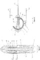
- the power cables terminate in a pair of spools which are on clutch bearings which are on the propeller shaft Before the cables terminate they wrap around the spools several times.
- One end of a third cable is terminated in the opposite end of the spool. This third cable makes several wraps around the spools and then proceeds deeper down into the rudder where it passes around a pulley which it turns it about 180 degrees. The cable then goes back up and makes several wraps around the other spool and terminates on the spool.
- the two power cables come down the rudder and each cable is split into two.
- the bottom of the rudder has one shaft free to rotate inside a hollow shaft which is free to rotate.
- the front of each shaft is fitted with a drum.
- the first power cable splits and one cable winds about 270 degrees around one of the drums and terminates to the drum.
- the other cable winds about 270 degrees around the other drum in the opposite direction and terminates to the drum.
- the second power cable splits and the two ends terminate on the drums in the same manner, but in the apposite direction.
- the final result is that when one cable is pulled the two drums turn in opposite direction.
- the second power cable is taken up or drawn around the two drums. Again as the two pedals move back and forth the two drums spin back and forth in opposite directions and thus the two concentric shafts spin in opposite directions.
- each shaft On the back of each shaft is mounted a pair of steel rods. On these steel rods is mounted two pairs of flexible fins.
- the internal shaft extends further aft and the aft pair of fins is mounted on the internal shaft. These flexible fins are free to rotate on the steel rod and fixed to the shaft in such a way that when the shaft turns and the fin is pushed through the water the fins twist and flex in such a way that it assumes the shape of a propeller blade.
- the flexible fins are able produce forward thrust regardless of which direction the shafts are turning.
- the power cables are relatively thin and flexible they can tolerate a certain amount of twisting as they travel down the rudder. This attribute will allow the cables to transmit power as the rudder is turned up to 270 degrees to the left and right. If the rudder is turned 90 degrees the boat will turn within its own length. If the rudder is turned 180 degrees it will go in reverse. The ability to turn the rudder more than 180 degrees will allow the pilot to steer left or right in reverse.
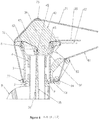
- An upper and lower set of ball bearings is provided to allow the rudder to turn about a vertical axis to steer the boat.
- the upper bearing must be sarge to create space for the two pulleys that turn the power cables 98 degrees into the rudder.
- the quadrant or a groove for the steering lines There are two lines - one turns the rudder to the right and the other turns the rudder to the left. From the centered position each line can turn the rudder 270 degrees right or left.
- the rudder is also able to rotate back and out of the water. It can continue for 270 degrees until it lays on the deck of the boat. It can also turn 90 degrees so that it lays flat on the deck. Special accommodations have been made for the power lines and the steering lines.
- the steering lines pass right through the center of rotation for this movement so the tension in the steering lines does not change as the rudder is rotating up.
- the power lines will come off of the 90 degree turning blocks and bend around to allow the rudder to rotate through 270 degrees.
- the propulsion device will work-you can pedal and create thrust while the rudder is rotating up until it reaches 90 degrees and the power cable will begin to rub. This will allow the drive to work in less water depth.
- the main aim of the design is to make a foot operated propulsion device for small watercraft that can be operated remotely.
- a foot powered craft is better because people tend to have a lot more power in their lower body and it leaves the hand free for other tasks.
- the pilot of the boat should be able to direct the direction of the thrust of the drive in any direction to steer and go in reverse. This will greatly improve the maneuverability of the boat.
- the pilot should be able to steer the boat with a small tiller. Combining the rudder and the propulsion device into one unit will simplify the boat.
- the pilot should be able to deploy and retract the drive from the seated position.
- the drive should be able to be stowed flat on the deck of the boat and then the pilot should be able to lock it into the normal operating position. If the drive hits an obstacle in the water, the drive should be released automatically to avoid damage.
- Folding props are common in sail boats and are relatively simple unless they are required to work in reverse because the blades will just fold. With the remote drive the propeller is always producing force in the same direction and the drive rotates 180 degrees to go into reverse so the folding propeller will be relatively simple,
- the remote drive has an advantage because the prop is always producing thrust in one direction.
- the thrust of a prop turning in the reverse direction is compromised because the propeller is designed to be more efficient in the forward direction.
- a rudder of a boat or plane will have between 85% and 60% of the rudder area behind the pivot line. So if the boat goes in reverse there is too much area ahead of the pivot line and the rudder will be unstable. The pilot will have to actively work to prevent the rudder from turning all the way to the stop. Since the rudder of the remote drive turns 180 degrees to go in reverse the balance of the rudder will always stay the same. This is an advantage for a fisherman who prefers to troll in reverse and watch his line in his wake.
- a further benefit of the invention is the ability to push the stern of the boat in any direction - forward, reverse or any angle in between which enable the boat to turn at any turning radius.
- a further benefit is the ability to retract the device and store it flat on the deck of the watercraft.
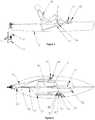
- the rudder bracket 1 is fastened to hull 2 with four #10 screws.
- the rudder mount 3 snaps into the rudder bracket 1 and can pivot 270 degrees.
- a set of ball bearings 5 is captured between the rudder quadrant 4 and the rudder mount 3 and the rudder quadrant 4 can rotate inside the rudder mount 3.
- a second set of ball bearings 7 is captured between the lower bearing 6 and the rudder mount 3 and the lower bearing 6 is free to rotate.
- Lower bearing 6 is fixed to the rudder quadrant 4 with 3 screws.
- the strut 9 slides into the lower bearing 6 and the rudder quadrant 4.
- the rudder 10 slides into the bottom of the strut 9 and is secured.
- the propeller assembly 11 slides into the rudder 10 and the rear bearing 17 is secured to the rudder 10 with a #10 screw.
- the pawl 12 slides into the recess in the rudder 10 is secured with a spring.
- the pawl 12 engages the ratchet in the propeller hub 14 and will prevent the propeller from rotating in a counter clockwise direction when looking at the drive from behind.
- the propeller shaft 15 is secured in the propeller 11 with a #10 screw.
- the rear bearing 17 and the spacer 18 are placed onto the shaft
- the rear bearing 17 and the spacer 18 are placed onto the shaft.
- the spacer 18 is secured to the shaft with a 1 ⁇ 4-20 set screw.
- a clutch bearing 19 is pressed into the front spool 21 and the rear spool 20.
- a plastic bushing 23 is placed inside the front spool 21 and the rear spool 20 on each side of the clutch bearing 19. The plastic bushing 23 keeps the spool centered on the propeller shaft 15 to minimize friction.
- An O ring 22 is placed inside each end of front spool 21 and rear spool 20 The O rings seal oil inside the spool for the clutch bearing and keep water and dirt out.
- the direction of the spiral cut in the front spool 21 is opposite from the rear spool 20
- the inside of the clutch bearing 19 has 10 hardened steel rods (.092" x .305") 25,
- the inside surface of the clutch bearing 19 has a ramp 27 for each steel rod 25.
- a plastic leaf spring 26 pushes the steel rod 25 onto the ramp 27.
- Power from the rider 30 is transmitted to the pedals 31 and 32 by moving the pedals back and forth with a stepping motion of the rider's 30 feet. Power from the pedals 31 and 32 is transmitted back to the rudder via a pair of power cables 33 and 34.
- a loop 52 is formed in the front end of twin pairs of power cables 35 and 36 with a swage 53. Power cables 33 and 34 are connected to the loop 52 of the twin pairs of power cable 35 and 36.
- the twin pairs of power cables 35 and 36 are made up of two smaller cables (nylon coated 1/16" 7x19 stainless steel) that are better suited for rounding the small diameter of the pulleys 37 and 38 and the front and rear spools 21 and 20.
- the twin pairs of power cables 35 and 36 come back and are turned by pulleys 37 and 38 and go drown through the strut 9 and into the rudder 10.
- Pulleys 37 and 38 are supported by 3/8" bolt 39.
- the 3/8" bolt 39 is supported by pulley support 40, 41 and 42.
- Pulley supports 40, 41 and 42 are fastened to the rudder mount 3 with 6 #10 screws.
- Cable capture device 43 is fastened to pulley supports 41 and 42 with 2 #6 screws. The cable capture device prevents the two cables from twisting as they go onto the pulleys 37 and 38.
- the twin pairs of power cables 35 and 36 come into the rudder 10 and begin to wrap around the front and rear spools 21 and 20 and are terminated in the front and rear spools 21 and 20 with a swage 46. Tension in the twin pairs of power cables 35 and 36 will cause the front and rear spools 21 and 20 to rotate in a clockwise direction while viewing the boat from the rear.
- the idler pulley cable 47 terminates in the front and rear spools 21 and 20 with a swage 51.
- the idler pulley cable 47 passes around the idler pulley 48 which is supported by idler pulley axle 49, Idler pulley door 50 covers the pulley and supports the idler pulley axle 49.
- the steering handle 60 is in close proximity to the left hand of the rider 30 who is located in the cockpit 8.
- the steering handle 60 is connected to the steering quadrant 61.
- the steering lines 62 and 63 are wrapped around the steering quadrant 61 and go aft to the rudder 10.
- the steering lines go through the rudder bracket 1 and rudder mount 3 and turn aft and wrap about 270 degrees around the rudder quadrant 4 and terminate with 2 knots 64 and 65 on the inside of the rudder quadrant.
- the steering handle 60 can be rotated to the right or the left up to 270 degrees which will cause equal amount of rotation of the rudder quadrant 4 in the opposite direction.
- the rider 30 pulls on the up line control handle which is attached to up control line 71.
- Pulleys 72, 73, and 74 direct the up control line 71 back to the remote drive.
- the up control line 71 passes over a line guide 75 on the top of the pulley support 40 and then passes over a line guide 76 on the rudder mount 3 and then it terminates with a knot in the rudder mount 3 at 77.
- Tension in the up control line 71 will cause the remote drive to rotate up about 270 degrees until it lays flat on the deck 78.
- the remote drive can be steered 90 degrees to the right or left so that it lays flat on the deck 78.
- the rider 30 pulls on the down line control handle 80 which is attached to down control line 81.
- Pulleys 82, 73, and 74 direct the down control line 81 aft to the remote drive.
- the down control line 81 passes over the sheaves 83 and 84 and then it terminates with a knot at 86.
- Figure 15 the invention of Figures 1 to 14 is adapted for use on catamarans.
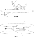
- FIGS 16, 17 , 18 and 19 show another embodiment of this invention.
- the twin pairs of power cables now 35 and 36 come back to the remote drive and are turned down into the rudder 10 with the pulleys 37 and 38.
- the left power cable pair 35 is then split and one cable goes around turning block 114 and one goes around turning block 112.
- the right drive cable pair 36 splits and one cable goes around the turning block 113 and one goes around turning block 115.
- the four cables go around the two drums 116 and 117 in opposite directions so that when drive cable pair 35 is pulled drums 116 and 117 turn in opposite directions and when drive cable pair 36 is pulled the drums 116 and 117 turn in the opposite directions.
- Drum 117 is connected to hub 111 and drum 116 is connected to hub 110.
- Hubs 111 and 110 rotate opposite each other with each stroke of pedals 31 and 32.
- Fins 118, 119, 120, 121 are flexible and assume the shape of propeller blade when forced through the water.
- Figures 20, 21 , 22, 23 , 24 , 25 and 26 show still another alternative embodiment of this invention in which human input power is transferred from the pedals 31 and 32 to the remote drive with hydraulic fluid (water) instead of tension cables.
- Force on the pedals 31 or 32 causes piston assemblies 91 or 92 to move forward. Movement of piston assemblies 91 or 92 causes increased pressure inside cylinders 93 and 94 and causes the water to move back to the remote drive in hose 95.
- the water travels down the rudder 9 through hose 95 and into the rotary valve 100.
- the rotary valve directs the water into the front of the crankshaft 104, Water passes through the crankshaft 104 and exits through the port 138.
- the water goes into the port 106 of the rotary valve 100.
- the water is directed to hose 102 which leads to the first of 3 cylinders 102 which is the power stroke.
- the water pressure forces the piston 103 down and turns crankshaft 104 through connecting rod 135 which turns the propeller 11 in the clockwise direction while viewing from the rear.
- Figure 24b shows the same section view but the propeller 11 and crankshaft 104 has been rotated 180 degrees and cylinder 102 is exhausting the water out through hose 101. The water passes back through port 106 of the rotary valve 100 and into the crankshaft 104. The water exits through port 105 in the crankshaft 104.
- Rotary valve 100 has 2 other ports 107 and 108. These ports direct water to or from cylinders 109 and 130 through hoses 131 and 132 when these ports 107 and 108 line up with the ports 105 or 138 of the crankshaft 104. Water pressure acts on pistons 133 and 134 and turns the crankshaft 104 through connecting rods 136 and 137.
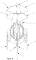
- FIGS 27 , 28 and 29 show yet another alternative embodiment of this invention which uses an electric motor and battery for power and thrust.
- a power cord 90 comes from a battery 140. which preferably is carried just behind the cockpit 8 and goes forward to the throttle control 141 which is located in convenient location for the rider 30 to operate. The power cord 90 then goes back to the stern and then goes down the rudder 10 and to the electric gearmotor 88.
- a clutch bearing 87 allows torque to go from the gearmotor 88 to the propeller assembly 11, but does not allow the torque to go into the gearmotor 88.
- a seal 89 prevents water from entering the gearmotor 88.
- the electric motor can also be used in conjunction with the human powered embodiments of Figures 1 to 25 .
Landscapes
- Chemical & Material Sciences (AREA)
- Engineering & Computer Science (AREA)
- Combustion & Propulsion (AREA)
- Mechanical Engineering (AREA)
- Ocean & Marine Engineering (AREA)
- Transmission Devices (AREA)
- Toys (AREA)
Claims (15)
- Véhicule nautique piloté comportant une proue et une poupe, un pont (78), un gouvernail (10) à la proue et un poste de pilotage (18) entre la proue et la poupe, comprenant :des moyens (31, 32) portés par le véhicule nautique comprenant une source de puissance de propulsion,caractérisée par :ledit gouvernail (10) étant librement rotatif dans une quelconque direction et porté autour d'un axe vertical et comportant à proximité de son extrémité inférieure une hélice (11) ou au moins une paire d'ailettes souples (118-121) à oscillation opposée permettant de propulser le véhicule nautique etdes moyens (33-38 ; 91-98) reliant ladite source de puissance de propulsion au fond dudit gouvernail (10) pour piloter à distance ledit ladite hélice (11) ou ladite au moins une paire d'ailettes souples (118-121) à oscillation opposée.
- Véhicule nautique selon la revendication 1,
ledit gouvernail (10) comportant à proximité de son extrémité inférieure un moteur électrique et
ledit véhicule nautique comprenant des moyens électriques (90) reliant ladite source de puissance de propulsion au fond dudit gouvernail pour actionner ledit moteur électrique et entraîner ladite hélice (11) ou lesdites ailettes (118-121),
ledit véhicule nautique comprenant éventuellement des moyens portés par le véhicule nautique comprenant une source électrique de puissance de propulsion,
la source de puissance de propulsion étant éventuellement un accumulateur. - Véhicule nautique selon la revendication 1 ou 2, dans lequel :lesdits moyens portés par le véhicule nautique comprenant une source de puissance de propulsion comprennent une paire de pédales (31, 32) permettant de recevoir une force d'entrée humaine, etledit véhicule nautique comprend des moyens reliant lesdites pédales (31, 32) audit fond dudit gouvernail destiné à entraîner ladite hélice comprenant des moyens de tension (33-38) s'étendant vers l'arrière desdites pédales (31, 32) à ladite proue et vers le bas pour actionner ladite hélice (11).
- Véhicule nautique selon la revendication 1 ou 2, dans lequel :lesdits moyens portés par le véhicule nautique comprenant une source de puissance de propulsion comprennent une paire de pédales (31, 32) permettant de recevoir une force d'entrée humaine,ledit véhicule nautique comprend une zone d'assise dans l'arrière dudit poste de pilotage desdites pédales permettant de porter un opérateur humain (30),ladite source de puissance de propulsion comprend des moyens hydrauliques (91, 92) reliés de manière fonctionnelle auxdites pédales (31, 32) pour générer une pression fluidique, etledit véhicule nautique comprend des moyens (93-98) acheminant ladite pression du fluide s'étendant en arrière desdits moyens hydrauliques à ladite proue et vers le bas pour un actionnement hydraulique de ladite hélice (11).
- Véhicule nautique selon les revendications 1 à 4, dans lequel :ledit gouvernail (10) s'étend au-dessous desdits moyens de propulsion en vue de la protection de ladite hélice (11) ou desdites ailettes (118-121), et/ouledit gouvernail (10) est rétractable et conçu pour être stocké au-dessus et sensiblement plat sur le pont arrière dudit véhicule nautique.
- Véhicule nautique selon les revendications 3 ou 4 comprenant en outre un siège de conducteur situé à l'arrière desdites pédales (31, 32) pour faciliter l'application de la puissance d'un pied humain,
des moyens de direction (60) situés de manière adjacente audit siège, et
des cordes reliant lesdits moyens de direction (60) audit gouvernail (10) de manière que l'opérateur peut entraîner ledit gouvernail à tourner librement autour dudit axe vertical pour diriger, lesdites cordes permettant audit gouvernail d'être rétractable,
ledit gouvernail (10) étant éventuellement rétractable vers le haut et lesdites cordes passant approximativement par le centre de rotation en vue d'une rétraction, permettant ainsi à la direction de se produire à un angle de rétraction dudit gouvernail (10). - Véhicule nautique selon la revendication 3, dans lequel des moyens de support espacés sont prévus au niveau d'une extrémité supérieure du gouvernail (10) en vue d'une rotation pour la rétraction ; lesdits moyens de support étant espacés latéralement pour permettre aux dits moyens de tension (33-38) de passer entre ceux-ci et de tourner vers le bas en direction de ladite hélice (11).
- Véhicule nautique selon la revendication 3, dans lequel l'hélice (11) est montée sur un arbre horizontal porté par le gouvernail (10).
- Véhicule nautique selon la revendication 8, dans lequel le gouvernail (10) est monté rotatif sur au moins un roulement de direction et lesdits moyens de tension (33-34) constituent une paire de câbles qui communiquent avec lesdites pédales (31, 32) et passent au-dessus de poulies à proximité dudit roulement de direction et tournent vers le bas pour entraîner ledit arbre horizontal,
lesdits câbles étant éventuellement conçus pour sortir desdites poulies lorsque ledit gouvernail (10) est rétracté. - Véhicule nautique selon la revendication 1, dans lequel l'au moins une paire d'ailettes (118-121) sont conçues pour être déplacées dans des directions opposées à travers la ligne centrale dudit véhicule nautique.
- Véhicule nautique selon les revendications 3 ou 4, dans lequel lesdites pédales (31, 32) sont conçues pour se déplacer en va-et-vient avec un mouvement de marche.
- Véhicule nautique selon la revendication 9, dans lequel lesdits roulements de direction sont des roulements à billes, et/ou une poulie de renvoi est positionnée au-dessous du dit arbre horizontal, ladite poulie de renvoi portant un câble qui est relié à des bobines avant et arrière et se termine au niveau de celles-ci.
- Véhicule nautique selon la revendication 9, dans lequel un de ladite paire de câbles se termine dans une bobine avant et l'autre câble se termine dans une bobine arrière, les deux bobines étant portées par ledit arbre horizontal de manière qu'une tension dans les câbles amène les bobines à tourner dans un sens horaire lorsque l'on regarde le véhicule nautique depuis l'arrière,
un roulement d'embrayage étant éventuellement enfoncé dans chacune desdites bobines avant et arrière. - Véhicule nautique selon la revendication 1, dans lequel lesdites ailettes (118-121) sont sous forme d'une pale d'hélice.
- Véhicule nautique selon les revendications 1 à 4, dans lequel l'embarcation est un catamaran.
Applications Claiming Priority (2)
| Application Number | Priority Date | Filing Date | Title |
|---|---|---|---|
| US20771509P | 2009-02-12 | 2009-02-12 | |
| PCT/US2010/024014 WO2010093863A1 (fr) | 2009-02-12 | 2010-02-12 | Actionnement à distance |
Publications (3)
| Publication Number | Publication Date |
|---|---|
| EP2396220A1 EP2396220A1 (fr) | 2011-12-21 |
| EP2396220A4 EP2396220A4 (fr) | 2013-06-05 |
| EP2396220B1 true EP2396220B1 (fr) | 2018-02-21 |
Family
ID=42540794
Family Applications (1)
| Application Number | Title | Priority Date | Filing Date |
|---|---|---|---|
| EP10741764.4A Not-in-force EP2396220B1 (fr) | 2009-02-12 | 2010-02-12 | Actionnement à distance |
Country Status (6)
| Country | Link |
|---|---|
| US (1) | US8753156B2 (fr) |
| EP (1) | EP2396220B1 (fr) |
| CN (1) | CN102317152B (fr) |
| AU (1) | AU2010213687B2 (fr) |
| ES (1) | ES2667844T3 (fr) |
| WO (1) | WO2010093863A1 (fr) |
Families Citing this family (25)
| Publication number | Priority date | Publication date | Assignee | Title |
|---|---|---|---|---|
| WO2013192099A1 (fr) * | 2012-06-22 | 2013-12-27 | Flow Sports, Inc. | Système de planche à rame muni de mécanisme de direction |
| WO2017019140A1 (fr) | 2015-07-30 | 2017-02-02 | Flow Sports, Inc. | Mécanisme de direction actionné au pied pour planches à rame à position debout |
| US9914519B2 (en) | 2016-06-30 | 2018-03-13 | Confluence Outdoor, Llc | Propulsion system for a watercraft |
| ES1189435Y (es) * | 2017-07-20 | 2017-10-31 | Alfaro Formosa Jose | Kayak con sistema de pedales asistidos por motor electrico |
| US10259553B2 (en) * | 2017-08-22 | 2019-04-16 | Hobie Cat Company | Propulsion device for watercraft |
| EP3511239A1 (fr) * | 2018-01-10 | 2019-07-17 | NGB Research & Development UG (haftungsbeschränkt) | Système de propulsion et de direction pour bateau |
| CN108545167B (zh) * | 2018-04-10 | 2023-05-02 | 衢州学院 | 自动力休闲船 |
| CN109045591B (zh) * | 2018-06-28 | 2020-06-09 | 江慧如 | 一种无臂残疾人水上娱乐用身体控制式体能锻炼滑行机 |
| CN109572970B (zh) * | 2018-12-24 | 2020-08-25 | 山东大学 | 一种水下机器人的矢量推进器 |
| US11649028B2 (en) | 2019-02-27 | 2023-05-16 | Pelican International Inc. | Watercraft having an interface for mounting a propulsion mechanism |
| US10829189B2 (en) | 2019-02-27 | 2020-11-10 | Pelican International Inc. | Interface for mounting a propulsion mechanism to a watercraft |
| US11148775B2 (en) | 2019-08-27 | 2021-10-19 | Johnson Outdoors Inc. | Watercraft and associated pedal drive system |
| USD920212S1 (en) * | 2019-10-04 | 2021-05-25 | Lifetime Products, Inc. | Pedal drive |
| CN111846182B (zh) * | 2019-10-30 | 2024-05-24 | 宁波市海曙鸿辉模具塑料厂 | 一种尾舵控制系统以及皮划艇 |
| US11390366B2 (en) * | 2020-01-28 | 2022-07-19 | Propulsion Powercycle Inc. | Electronic control module for electrically assisted pedal-powered boat |
| US11572143B2 (en) | 2020-03-12 | 2023-02-07 | Johnson Outdoors Inc. | Watercraft and associated pedal drive system |
| USD939421S1 (en) * | 2020-08-04 | 2021-12-28 | Cixi Luosaifei Kayak Co., Ltd. | Pedal drive for kayak |
| USD939422S1 (en) * | 2020-08-04 | 2021-12-28 | Cixi Luosaifei Kayak Co., Ltd. | Foldable pedal drive for kayak |
| US11390367B2 (en) | 2020-09-03 | 2022-07-19 | Hobie Cat Ip, Llc | Modular rudder system |
| US12479558B2 (en) | 2021-04-07 | 2025-11-25 | White River Marine Group, Llc | Support assemblies for watercrafts and related methods of assembly |
| US12384493B2 (en) * | 2021-12-10 | 2025-08-12 | Hobie Cat Ip, Llc | Drain mechanism for watercraft |
| CN216611567U (zh) * | 2021-12-29 | 2022-05-27 | 福建渡远户外运动用品有限公司 | 一种船艇上的脚踏安装结构 |
| US11878776B1 (en) | 2022-08-01 | 2024-01-23 | Randall G. Haynes | Kayak motor and motor mounting apparatus |
| USD1020599S1 (en) | 2022-11-03 | 2024-04-02 | Randall G. Haynes | Combined kayak motor and motor mounting apparatus |
| US20260054810A1 (en) * | 2024-08-20 | 2026-02-26 | Johnson Outdoors Inc. | Clutch System for a Trolling Motor and Unexpected Trim Event Sensor |
Family Cites Families (61)
| Publication number | Priority date | Publication date | Assignee | Title |
|---|---|---|---|---|
| US35451A (en) * | 1862-06-03 | Improved marine propeller | ||
| GB174017A (en) | 1920-07-07 | 1922-01-09 | Anton Flettner | Improved steering devices for ships and the like |
| US1826507A (en) * | 1931-05-27 | 1931-10-06 | Roy T Crosby | Propelling means for boats and the like |
| US2158349A (en) * | 1934-11-28 | 1939-05-16 | Clarence W Allen | Propelling mechanism |
| GB452719A (en) | 1935-02-25 | 1936-08-25 | Friedrich Budig | Improvements in propulsion means for water craft |
| US2286914A (en) * | 1941-03-10 | 1942-06-16 | Merton L Knapp | Rowboat attachment |
| US2873713A (en) * | 1955-12-01 | 1959-02-17 | Aage I Baastrup | Hand-operated mechanism for propelling boats and canoes |
| US2948255A (en) * | 1956-08-09 | 1960-08-09 | Sbrana Adolphe | Nautical propulsion system using webs and craft fitted with such system |
| US3032001A (en) * | 1960-08-17 | 1962-05-01 | Gadget Of The Month Club Inc | Pedally operable boat propulsion apparatus |
| US3095850A (en) * | 1961-04-27 | 1963-07-02 | Forrest L Stolzer | Foot operated boat paddle |
| US3211125A (en) * | 1964-06-12 | 1965-10-12 | Fenner M Yarbrough | Combination rudder and propeller drive assembly |
| US3695211A (en) * | 1970-05-07 | 1972-10-03 | William J Gross | Self-propelled boat |
| US3828719A (en) * | 1972-04-03 | 1974-08-13 | C Cooke | Hydraulic propulsion unit |
| JPS5233290A (en) | 1975-09-05 | 1977-03-14 | Mikio Maruyama | Manual propulsion apparatus |
| US4318700A (en) * | 1980-04-09 | 1982-03-09 | Price Charles D | Paddle wheel operated watercraft |
| US4511338A (en) * | 1983-03-04 | 1985-04-16 | Noel Fanelli | Water bicycle and detachable device therefor |
| US4490119A (en) * | 1983-03-21 | 1984-12-25 | Young Ronald G | Boat propulsion apparatus |
| US4474502A (en) * | 1983-05-31 | 1984-10-02 | Mohamed Daoud | Water sporting boat |
| US4688815A (en) * | 1984-03-27 | 1987-08-25 | Lectrolarm Custom Systems, Inc. | Hydraulically driven bicycle |
| US4648846A (en) * | 1985-05-29 | 1987-03-10 | Hsu Chen Hsiung | Pedal boat |
| US4676755A (en) * | 1985-11-13 | 1987-06-30 | Erse Yagan | Pedal driven device |
| WO1988001966A1 (fr) * | 1986-09-22 | 1988-03-24 | Rybczyk Joseph A | Dispositif de propulsion actionne par la force musculaire |
| JPH01144198A (ja) | 1987-11-30 | 1989-06-06 | Nissin Electric Co Ltd | 異常過熱検出方法 |
| US4960396A (en) * | 1988-01-19 | 1990-10-02 | Lawerence Stolzer | Foot-operated boat paddle propulsion system |
| US4891024A (en) * | 1988-04-20 | 1990-01-02 | Benjamin Robert J | Pedal boat propulsion system |
| US4936802A (en) * | 1989-02-02 | 1990-06-26 | Sunaga Kaihatsu Kabushiki Kaisha | Swinging and propelling ship |
| JPH0686033B2 (ja) | 1989-07-03 | 1994-11-02 | 日本国土開発株式会社 | 鉄筋の溶接継手用バッキング部材 |
| US4968274A (en) * | 1989-07-13 | 1990-11-06 | Gregory Jack T | Pedal operated watercraft |
| US4943251A (en) * | 1989-08-02 | 1990-07-24 | Yamaha Hatsudoki Kabushiki Kaisha | Pedal operated outboard motor for watercraft |
| US5021015A (en) * | 1990-02-20 | 1991-06-04 | Wang June Chi | Propulsion mechanism for a boat |
| US5102359A (en) * | 1991-02-14 | 1992-04-07 | Hinds William R | Thrust director and stand |
| US5295927A (en) * | 1991-11-27 | 1994-03-22 | Fitness Master, Inc. | Stepper exercise machine |
| US5194024A (en) * | 1991-12-02 | 1993-03-16 | Shiraki Wilton F | Propeller driven surfboard |
| US5183422A (en) * | 1992-03-12 | 1993-02-02 | Thomas Guiboche | Pedal boat |
| US5453031A (en) * | 1994-07-19 | 1995-09-26 | Gagnier; David L. | Hand propulsion device for a paddle boat |
| US5460551A (en) * | 1994-08-05 | 1995-10-24 | Beres; Jeffrey W. | Pedal-powered kayak |
| US5580288A (en) * | 1995-09-29 | 1996-12-03 | Marinc; Victor | Belt driven pedal boat |
| US5584732A (en) * | 1996-01-11 | 1996-12-17 | Kakor Inc. | Human-powered watercraft paddle propulsion system |
| US5643020A (en) * | 1996-08-13 | 1997-07-01 | Harris; Herman R. | Personal watercraft |
| US6022249A (en) * | 1997-07-30 | 2000-02-08 | R.R. Sail Inc. | Watercraft |
| US6077134A (en) * | 1997-08-29 | 2000-06-20 | Lam; Warren | Combination bicycle and boat |
| GB9811376D0 (en) | 1998-05-27 | 1998-07-22 | Apax Vehicle Developments Inc | Hydraulic drive system |
| US6112692A (en) * | 1998-07-01 | 2000-09-05 | Step Jet Corporation | Dual hull kayak |
| US6165029A (en) * | 1999-07-06 | 2000-12-26 | Lu; Hsueh-Liang | Pedal boat |
| US6210242B1 (en) * | 1999-10-13 | 2001-04-03 | Harry Howard | Pedal-powered watercraft |
| US6165030A (en) * | 2000-04-25 | 2000-12-26 | Lewis; Robert M. | Pedal driven propulsion device |
| US6478639B1 (en) * | 2000-07-17 | 2002-11-12 | Covell, Iii Edward H. | Watercraft having jet propulsion and electric outdrive |
| FR2815472B1 (fr) * | 2000-10-13 | 2003-03-21 | St Microelectronics Sa | Diac planar |
| US6855016B1 (en) * | 2002-07-16 | 2005-02-15 | Patrick Lee Jansen | Electric watercycle with variable electronic gearing and human power amplification |
| US6997765B1 (en) * | 2003-05-14 | 2006-02-14 | Mcguinness Thomas G | Vessel propelled by oscillating fin with control mechanisms |
| ATE305406T1 (de) | 2003-05-17 | 2005-10-15 | Klaus Spass | Boot mit tretantrieb |
| US6905379B1 (en) * | 2003-11-28 | 2005-06-14 | Reinhard Erwin Jackson | Portable canoe propulsion system |
| US7637791B2 (en) * | 2005-08-08 | 2009-12-29 | Hobie Cat Company | Fin for oscillating foil propulsion system |
| US7430976B2 (en) | 2006-08-02 | 2008-10-07 | Hobie Cat Co. | Twist and stow rudder |
| US7549902B2 (en) * | 2006-11-02 | 2009-06-23 | Patrick Lee Jansen | Electric motor assisted propulsion system for human-powered watercraft |
| US7430786B1 (en) * | 2007-04-23 | 2008-10-07 | Shin Zu Shing Co., Ltd. | Triple positioning hinge |
| US20080293312A1 (en) | 2007-05-21 | 2008-11-27 | Sean Scott | Marine propulsion device |
| US8167667B2 (en) * | 2007-05-24 | 2012-05-01 | Sturm Rex L | Watercraft for transportation and exercise |
| US8276536B2 (en) * | 2008-02-04 | 2012-10-02 | James Winsky | Rudder system |
| EP2202142B1 (fr) * | 2008-12-23 | 2013-09-25 | Dolprop Industries Ab | Dispositif de propulsion de bateau |
| WO2011011006A1 (fr) * | 2009-07-23 | 2011-01-27 | James Winsky | Système de gouvernail |
-
2010
- 2010-02-11 US US12/704,454 patent/US8753156B2/en active Active
- 2010-02-12 ES ES10741764.4T patent/ES2667844T3/es active Active
- 2010-02-12 CN CN201080007782.1A patent/CN102317152B/zh not_active Expired - Fee Related
- 2010-02-12 EP EP10741764.4A patent/EP2396220B1/fr not_active Not-in-force
- 2010-02-12 AU AU2010213687A patent/AU2010213687B2/en not_active Ceased
- 2010-02-12 WO PCT/US2010/024014 patent/WO2010093863A1/fr not_active Ceased
Non-Patent Citations (1)
| Title |
|---|
| None * |
Also Published As
| Publication number | Publication date |
|---|---|
| AU2010213687A1 (en) | 2011-09-01 |
| CN102317152B (zh) | 2015-12-16 |
| ES2667844T3 (es) | 2018-05-14 |
| US8753156B2 (en) | 2014-06-17 |
| US20100203778A1 (en) | 2010-08-12 |
| WO2010093863A1 (fr) | 2010-08-19 |
| EP2396220A4 (fr) | 2013-06-05 |
| AU2010213687B2 (en) | 2012-05-03 |
| EP2396220A1 (fr) | 2011-12-21 |
| CN102317152A (zh) | 2012-01-11 |
Similar Documents
| Publication | Publication Date | Title |
|---|---|---|
| EP2396220B1 (fr) | Actionnement à distance | |
| US8408954B2 (en) | Watercraft for transportation and exercise | |
| US6523489B2 (en) | Personal watercraft and off-power steering system for a personal watercraft | |
| AU2018214002B2 (en) | Steering mechanism for a boat having a planing hull | |
| US8276536B2 (en) | Rudder system | |
| JP2001512077A (ja) | 船 | |
| FI96757C (fi) | Peräsin- ja potkurijärjestelmä | |
| US8992272B1 (en) | Stand-up pedal board | |
| US5194024A (en) | Propeller driven surfboard | |
| EP1970302B1 (fr) | Système oscillant de propulsion et de direction d'hydroptère | |
| US7001229B2 (en) | Water vehicle propeller | |
| JP4014236B2 (ja) | 第1の船と第2の船が連結された海上輸送装置 | |
| KR100893218B1 (ko) | 회전 가능한 유선형 활대를 포함하는 돛단배 | |
| HK1163624A (en) | Remote drive | |
| US20100291815A1 (en) | Watercraft Propulsion System | |
| JPH0487896A (ja) | 足力推進カヌー及びこれに用いる操舵装置 | |
| EP2443030A1 (fr) | Système de propulsion et de direction de bateau avec rotors totalement immergés | |
| RU2075422C1 (ru) | Судовой гусеничный лопастной движитель | |
| GB2611287A (en) | Hand-powered watercraft | |
| JPH10218097A (ja) | ヨットの操舵装置 | |
| GB2443676A (en) | Manual boat propulsion system |
Legal Events
| Date | Code | Title | Description |
|---|---|---|---|
| PUAI | Public reference made under article 153(3) epc to a published international application that has entered the european phase |
Free format text: ORIGINAL CODE: 0009012 |
|
| 17P | Request for examination filed |
Effective date: 20110812 |
|
| AK | Designated contracting states |
Kind code of ref document: A1 Designated state(s): AT BE BG CH CY CZ DE DK EE ES FI FR GB GR HR HU IE IS IT LI LT LU LV MC MK MT NL NO PL PT RO SE SI SK SM TR |
|
| DAX | Request for extension of the european patent (deleted) | ||
| A4 | Supplementary search report drawn up and despatched |
Effective date: 20130507 |
|
| RIC1 | Information provided on ipc code assigned before grant |
Ipc: B63H 25/42 20060101AFI20130430BHEP Ipc: B63H 16/16 20060101ALN20130430BHEP |
|
| REG | Reference to a national code |
Ref country code: DE Ref legal event code: R079 Ref document number: 602010048623 Country of ref document: DE Free format text: PREVIOUS MAIN CLASS: B63H0025060000 Ipc: B63H0025420000 |
|
| GRAP | Despatch of communication of intention to grant a patent |
Free format text: ORIGINAL CODE: EPIDOSNIGR1 |
|
| STAA | Information on the status of an ep patent application or granted ep patent |
Free format text: STATUS: GRANT OF PATENT IS INTENDED |
|
| RIC1 | Information provided on ipc code assigned before grant |
Ipc: B63H 16/16 20060101ALN20170925BHEP Ipc: B63H 25/42 20060101AFI20170925BHEP |
|
| INTG | Intention to grant announced |
Effective date: 20171027 |
|
| RIC1 | Information provided on ipc code assigned before grant |
Ipc: B63H 25/42 20060101AFI20171016BHEP Ipc: B63H 16/16 20060101ALN20171016BHEP |
|
| GRAS | Grant fee paid |
Free format text: ORIGINAL CODE: EPIDOSNIGR3 |
|
| GRAA | (expected) grant |
Free format text: ORIGINAL CODE: 0009210 |
|
| STAA | Information on the status of an ep patent application or granted ep patent |
Free format text: STATUS: THE PATENT HAS BEEN GRANTED |
|
| AK | Designated contracting states |
Kind code of ref document: B1 Designated state(s): AT BE BG CH CY CZ DE DK EE ES FI FR GB GR HR HU IE IS IT LI LT LU LV MC MK MT NL NO PL PT RO SE SI SK SM TR |
|
| REG | Reference to a national code |
Ref country code: GB Ref legal event code: FG4D |
|
| REG | Reference to a national code |
Ref country code: CH Ref legal event code: EP |
|
| REG | Reference to a national code |
Ref country code: AT Ref legal event code: REF Ref document number: 971410 Country of ref document: AT Kind code of ref document: T Effective date: 20180315 |
|
| REG | Reference to a national code |
Ref country code: IE Ref legal event code: FG4D |
|
| REG | Reference to a national code |
Ref country code: DE Ref legal event code: R096 Ref document number: 602010048623 Country of ref document: DE |
|
| REG | Reference to a national code |
Ref country code: NL Ref legal event code: FP |
|
| REG | Reference to a national code |
Ref country code: ES Ref legal event code: FG2A Ref document number: 2667844 Country of ref document: ES Kind code of ref document: T3 Effective date: 20180514 |
|
| REG | Reference to a national code |
Ref country code: LT Ref legal event code: MG4D |
|
| REG | Reference to a national code |
Ref country code: AT Ref legal event code: MK05 Ref document number: 971410 Country of ref document: AT Kind code of ref document: T Effective date: 20180221 |
|
| PG25 | Lapsed in a contracting state [announced via postgrant information from national office to epo] |
Ref country code: CY Free format text: LAPSE BECAUSE OF FAILURE TO SUBMIT A TRANSLATION OF THE DESCRIPTION OR TO PAY THE FEE WITHIN THE PRESCRIBED TIME-LIMIT Effective date: 20180221 Ref country code: FI Free format text: LAPSE BECAUSE OF FAILURE TO SUBMIT A TRANSLATION OF THE DESCRIPTION OR TO PAY THE FEE WITHIN THE PRESCRIBED TIME-LIMIT Effective date: 20180221 Ref country code: NO Free format text: LAPSE BECAUSE OF FAILURE TO SUBMIT A TRANSLATION OF THE DESCRIPTION OR TO PAY THE FEE WITHIN THE PRESCRIBED TIME-LIMIT Effective date: 20180521 Ref country code: LT Free format text: LAPSE BECAUSE OF FAILURE TO SUBMIT A TRANSLATION OF THE DESCRIPTION OR TO PAY THE FEE WITHIN THE PRESCRIBED TIME-LIMIT Effective date: 20180221 Ref country code: HR Free format text: LAPSE BECAUSE OF FAILURE TO SUBMIT A TRANSLATION OF THE DESCRIPTION OR TO PAY THE FEE WITHIN THE PRESCRIBED TIME-LIMIT Effective date: 20180221 |
|
| PG25 | Lapsed in a contracting state [announced via postgrant information from national office to epo] |
Ref country code: LV Free format text: LAPSE BECAUSE OF FAILURE TO SUBMIT A TRANSLATION OF THE DESCRIPTION OR TO PAY THE FEE WITHIN THE PRESCRIBED TIME-LIMIT Effective date: 20180221 Ref country code: SE Free format text: LAPSE BECAUSE OF FAILURE TO SUBMIT A TRANSLATION OF THE DESCRIPTION OR TO PAY THE FEE WITHIN THE PRESCRIBED TIME-LIMIT Effective date: 20180221 Ref country code: AT Free format text: LAPSE BECAUSE OF FAILURE TO SUBMIT A TRANSLATION OF THE DESCRIPTION OR TO PAY THE FEE WITHIN THE PRESCRIBED TIME-LIMIT Effective date: 20180221 Ref country code: BG Free format text: LAPSE BECAUSE OF FAILURE TO SUBMIT A TRANSLATION OF THE DESCRIPTION OR TO PAY THE FEE WITHIN THE PRESCRIBED TIME-LIMIT Effective date: 20180521 Ref country code: GR Free format text: LAPSE BECAUSE OF FAILURE TO SUBMIT A TRANSLATION OF THE DESCRIPTION OR TO PAY THE FEE WITHIN THE PRESCRIBED TIME-LIMIT Effective date: 20180522 |
|
| PG25 | Lapsed in a contracting state [announced via postgrant information from national office to epo] |
Ref country code: RO Free format text: LAPSE BECAUSE OF FAILURE TO SUBMIT A TRANSLATION OF THE DESCRIPTION OR TO PAY THE FEE WITHIN THE PRESCRIBED TIME-LIMIT Effective date: 20180221 Ref country code: PL Free format text: LAPSE BECAUSE OF FAILURE TO SUBMIT A TRANSLATION OF THE DESCRIPTION OR TO PAY THE FEE WITHIN THE PRESCRIBED TIME-LIMIT Effective date: 20180221 Ref country code: EE Free format text: LAPSE BECAUSE OF FAILURE TO SUBMIT A TRANSLATION OF THE DESCRIPTION OR TO PAY THE FEE WITHIN THE PRESCRIBED TIME-LIMIT Effective date: 20180221 |
|
| REG | Reference to a national code |
Ref country code: DE Ref legal event code: R097 Ref document number: 602010048623 Country of ref document: DE |
|
| PG25 | Lapsed in a contracting state [announced via postgrant information from national office to epo] |
Ref country code: SM Free format text: LAPSE BECAUSE OF FAILURE TO SUBMIT A TRANSLATION OF THE DESCRIPTION OR TO PAY THE FEE WITHIN THE PRESCRIBED TIME-LIMIT Effective date: 20180221 Ref country code: SK Free format text: LAPSE BECAUSE OF FAILURE TO SUBMIT A TRANSLATION OF THE DESCRIPTION OR TO PAY THE FEE WITHIN THE PRESCRIBED TIME-LIMIT Effective date: 20180221 Ref country code: DK Free format text: LAPSE BECAUSE OF FAILURE TO SUBMIT A TRANSLATION OF THE DESCRIPTION OR TO PAY THE FEE WITHIN THE PRESCRIBED TIME-LIMIT Effective date: 20180221 Ref country code: CZ Free format text: LAPSE BECAUSE OF FAILURE TO SUBMIT A TRANSLATION OF THE DESCRIPTION OR TO PAY THE FEE WITHIN THE PRESCRIBED TIME-LIMIT Effective date: 20180221 |
|
| PLBE | No opposition filed within time limit |
Free format text: ORIGINAL CODE: 0009261 |
|
| STAA | Information on the status of an ep patent application or granted ep patent |
Free format text: STATUS: NO OPPOSITION FILED WITHIN TIME LIMIT |
|
| 26N | No opposition filed |
Effective date: 20181122 |
|
| PG25 | Lapsed in a contracting state [announced via postgrant information from national office to epo] |
Ref country code: SI Free format text: LAPSE BECAUSE OF FAILURE TO SUBMIT A TRANSLATION OF THE DESCRIPTION OR TO PAY THE FEE WITHIN THE PRESCRIBED TIME-LIMIT Effective date: 20180221 |
|
| PGFP | Annual fee paid to national office [announced via postgrant information from national office to epo] |
Ref country code: NL Payment date: 20190214 Year of fee payment: 10 |
|
| PGFP | Annual fee paid to national office [announced via postgrant information from national office to epo] |
Ref country code: DE Payment date: 20190129 Year of fee payment: 10 Ref country code: FR Payment date: 20190111 Year of fee payment: 10 Ref country code: IT Payment date: 20190221 Year of fee payment: 10 Ref country code: ES Payment date: 20190301 Year of fee payment: 10 |
|
| REG | Reference to a national code |
Ref country code: CH Ref legal event code: PL |
|
| GBPC | Gb: european patent ceased through non-payment of renewal fee |
Effective date: 20190212 |
|
| PG25 | Lapsed in a contracting state [announced via postgrant information from national office to epo] |
Ref country code: LU Free format text: LAPSE BECAUSE OF NON-PAYMENT OF DUE FEES Effective date: 20190212 Ref country code: MC Free format text: LAPSE BECAUSE OF FAILURE TO SUBMIT A TRANSLATION OF THE DESCRIPTION OR TO PAY THE FEE WITHIN THE PRESCRIBED TIME-LIMIT Effective date: 20180221 |
|
| REG | Reference to a national code |
Ref country code: BE Ref legal event code: MM Effective date: 20190228 |
|
| REG | Reference to a national code |
Ref country code: IE Ref legal event code: MM4A |
|
| PG25 | Lapsed in a contracting state [announced via postgrant information from national office to epo] |
Ref country code: LI Free format text: LAPSE BECAUSE OF NON-PAYMENT OF DUE FEES Effective date: 20190228 Ref country code: CH Free format text: LAPSE BECAUSE OF NON-PAYMENT OF DUE FEES Effective date: 20190228 |
|
| PG25 | Lapsed in a contracting state [announced via postgrant information from national office to epo] |
Ref country code: GB Free format text: LAPSE BECAUSE OF NON-PAYMENT OF DUE FEES Effective date: 20190212 Ref country code: IE Free format text: LAPSE BECAUSE OF NON-PAYMENT OF DUE FEES Effective date: 20190212 |
|
| PG25 | Lapsed in a contracting state [announced via postgrant information from national office to epo] |
Ref country code: BE Free format text: LAPSE BECAUSE OF NON-PAYMENT OF DUE FEES Effective date: 20190228 |
|
| PG25 | Lapsed in a contracting state [announced via postgrant information from national office to epo] |
Ref country code: TR Free format text: LAPSE BECAUSE OF FAILURE TO SUBMIT A TRANSLATION OF THE DESCRIPTION OR TO PAY THE FEE WITHIN THE PRESCRIBED TIME-LIMIT Effective date: 20180221 |
|
| PG25 | Lapsed in a contracting state [announced via postgrant information from national office to epo] |
Ref country code: PT Free format text: LAPSE BECAUSE OF FAILURE TO SUBMIT A TRANSLATION OF THE DESCRIPTION OR TO PAY THE FEE WITHIN THE PRESCRIBED TIME-LIMIT Effective date: 20180621 Ref country code: MT Free format text: LAPSE BECAUSE OF NON-PAYMENT OF DUE FEES Effective date: 20190212 |
|
| REG | Reference to a national code |
Ref country code: DE Ref legal event code: R119 Ref document number: 602010048623 Country of ref document: DE |
|
| REG | Reference to a national code |
Ref country code: NL Ref legal event code: MM Effective date: 20200301 |
|
| PG25 | Lapsed in a contracting state [announced via postgrant information from national office to epo] |
Ref country code: NL Free format text: LAPSE BECAUSE OF NON-PAYMENT OF DUE FEES Effective date: 20200301 |
|
| PG25 | Lapsed in a contracting state [announced via postgrant information from national office to epo] |
Ref country code: DE Free format text: LAPSE BECAUSE OF NON-PAYMENT OF DUE FEES Effective date: 20200901 Ref country code: FR Free format text: LAPSE BECAUSE OF NON-PAYMENT OF DUE FEES Effective date: 20200229 |
|
| PG25 | Lapsed in a contracting state [announced via postgrant information from national office to epo] |
Ref country code: IS Free format text: LAPSE BECAUSE OF FAILURE TO SUBMIT A TRANSLATION OF THE DESCRIPTION OR TO PAY THE FEE WITHIN THE PRESCRIBED TIME-LIMIT Effective date: 20180621 |
|
| REG | Reference to a national code |
Ref country code: ES Ref legal event code: FD2A Effective date: 20210706 |
|
| PG25 | Lapsed in a contracting state [announced via postgrant information from national office to epo] |
Ref country code: HU Free format text: LAPSE BECAUSE OF FAILURE TO SUBMIT A TRANSLATION OF THE DESCRIPTION OR TO PAY THE FEE WITHIN THE PRESCRIBED TIME-LIMIT; INVALID AB INITIO Effective date: 20100212 |
|
| PG25 | Lapsed in a contracting state [announced via postgrant information from national office to epo] |
Ref country code: ES Free format text: LAPSE BECAUSE OF NON-PAYMENT OF DUE FEES Effective date: 20200213 |
|
| PG25 | Lapsed in a contracting state [announced via postgrant information from national office to epo] |
Ref country code: IT Free format text: LAPSE BECAUSE OF NON-PAYMENT OF DUE FEES Effective date: 20200212 |
|
| PG25 | Lapsed in a contracting state [announced via postgrant information from national office to epo] |
Ref country code: MK Free format text: LAPSE BECAUSE OF FAILURE TO SUBMIT A TRANSLATION OF THE DESCRIPTION OR TO PAY THE FEE WITHIN THE PRESCRIBED TIME-LIMIT Effective date: 20180221 |