EP2396802B1 - Lampe à décharge à haute pression - Google Patents
Lampe à décharge à haute pression Download PDFInfo
- Publication number
- EP2396802B1 EP2396802B1 EP10702132A EP10702132A EP2396802B1 EP 2396802 B1 EP2396802 B1 EP 2396802B1 EP 10702132 A EP10702132 A EP 10702132A EP 10702132 A EP10702132 A EP 10702132A EP 2396802 B1 EP2396802 B1 EP 2396802B1
- Authority
- EP
- European Patent Office
- Prior art keywords
- layers
- layer
- high pressure
- discharge lamp
- pressure discharge
- Prior art date
- Legal status (The legal status is an assumption and is not a legal conclusion. Google has not performed a legal analysis and makes no representation as to the accuracy of the status listed.)
- Not-in-force
Links
- 239000011195 cermet Substances 0.000 claims description 58
- 239000000463 material Substances 0.000 claims description 45
- 239000000919 ceramic Substances 0.000 claims description 25
- 238000000034 method Methods 0.000 claims description 14
- 239000000203 mixture Substances 0.000 claims description 14
- 229910052750 molybdenum Inorganic materials 0.000 claims description 14
- 238000004519 manufacturing process Methods 0.000 claims description 12
- 239000000843 powder Substances 0.000 claims description 9
- 229910052751 metal Inorganic materials 0.000 claims description 8
- 239000002184 metal Substances 0.000 claims description 8
- 239000011888 foil Substances 0.000 claims description 6
- 229910052721 tungsten Inorganic materials 0.000 claims description 5
- 230000007423 decrease Effects 0.000 claims description 2
- PNEYBMLMFCGWSK-UHFFFAOYSA-N aluminium oxide Inorganic materials [O-2].[O-2].[O-2].[Al+3].[Al+3] PNEYBMLMFCGWSK-UHFFFAOYSA-N 0.000 claims 1
- 229910052593 corundum Inorganic materials 0.000 claims 1
- 238000010030 laminating Methods 0.000 claims 1
- 238000004080 punching Methods 0.000 claims 1
- 238000010008 shearing Methods 0.000 claims 1
- 229910001845 yogo sapphire Inorganic materials 0.000 claims 1
- 239000010408 film Substances 0.000 description 18
- 229910018072 Al 2 O 3 Inorganic materials 0.000 description 17
- 230000006978 adaptation Effects 0.000 description 11
- 229910000679 solder Inorganic materials 0.000 description 11
- 238000007789 sealing Methods 0.000 description 8
- 238000005245 sintering Methods 0.000 description 8
- 230000008859 change Effects 0.000 description 6
- ZOKXTWBITQBERF-UHFFFAOYSA-N Molybdenum Chemical compound [Mo] ZOKXTWBITQBERF-UHFFFAOYSA-N 0.000 description 5
- 230000008901 benefit Effects 0.000 description 5
- 239000011733 molybdenum Substances 0.000 description 5
- 238000005516 engineering process Methods 0.000 description 4
- BASFCYQUMIYNBI-UHFFFAOYSA-N platinum Chemical compound [Pt] BASFCYQUMIYNBI-UHFFFAOYSA-N 0.000 description 4
- 230000015572 biosynthetic process Effects 0.000 description 3
- 239000002131 composite material Substances 0.000 description 3
- 229910001507 metal halide Inorganic materials 0.000 description 3
- 150000005309 metal halides Chemical class 0.000 description 3
- 230000008569 process Effects 0.000 description 3
- 238000007598 dipping method Methods 0.000 description 2
- 239000011159 matrix material Substances 0.000 description 2
- 229910052697 platinum Inorganic materials 0.000 description 2
- 229920000642 polymer Polymers 0.000 description 2
- 238000005507 spraying Methods 0.000 description 2
- 239000010409 thin film Substances 0.000 description 2
- -1 Mo or W Chemical class 0.000 description 1
- 238000003723 Smelting Methods 0.000 description 1
- 229910052782 aluminium Inorganic materials 0.000 description 1
- XAGFODPZIPBFFR-UHFFFAOYSA-N aluminium Chemical compound [Al] XAGFODPZIPBFFR-UHFFFAOYSA-N 0.000 description 1
- 238000005266 casting Methods 0.000 description 1
- 150000001875 compounds Chemical class 0.000 description 1
- 239000004567 concrete Substances 0.000 description 1
- 238000010276 construction Methods 0.000 description 1
- 238000001816 cooling Methods 0.000 description 1
- 238000005260 corrosion Methods 0.000 description 1
- 230000007797 corrosion Effects 0.000 description 1
- 230000003247 decreasing effect Effects 0.000 description 1
- 230000032798 delamination Effects 0.000 description 1
- 230000001419 dependent effect Effects 0.000 description 1
- 239000002019 doping agent Substances 0.000 description 1
- 230000009977 dual effect Effects 0.000 description 1
- 230000000694 effects Effects 0.000 description 1
- 238000009472 formulation Methods 0.000 description 1
- 239000011521 glass Substances 0.000 description 1
- 238000000227 grinding Methods 0.000 description 1
- 238000010438 heat treatment Methods 0.000 description 1
- 230000006872 improvement Effects 0.000 description 1
- 229910052741 iridium Inorganic materials 0.000 description 1
- 238000005304 joining Methods 0.000 description 1
- 239000000155 melt Substances 0.000 description 1
- QSHDDOUJBYECFT-UHFFFAOYSA-N mercury Chemical compound [Hg] QSHDDOUJBYECFT-UHFFFAOYSA-N 0.000 description 1
- 229910052753 mercury Inorganic materials 0.000 description 1
- 150000002739 metals Chemical class 0.000 description 1
- 238000000465 moulding Methods 0.000 description 1
- 239000002245 particle Substances 0.000 description 1
- 239000004014 plasticizer Substances 0.000 description 1
- 229910001404 rare earth metal oxide Inorganic materials 0.000 description 1
- 229910052702 rhenium Inorganic materials 0.000 description 1
- 238000007790 scraping Methods 0.000 description 1
- 238000007493 shaping process Methods 0.000 description 1
- 239000002002 slurry Substances 0.000 description 1
- 238000005476 soldering Methods 0.000 description 1
- 239000007787 solid Substances 0.000 description 1
- 239000002904 solvent Substances 0.000 description 1
- 239000000126 substance Substances 0.000 description 1
- 230000001629 suppression Effects 0.000 description 1
- 230000009885 systemic effect Effects 0.000 description 1
- 230000000930 thermomechanical effect Effects 0.000 description 1
- 230000007704 transition Effects 0.000 description 1
- 238000004804 winding Methods 0.000 description 1
Images


Classifications
-
- H—ELECTRICITY
- H01—ELECTRIC ELEMENTS
- H01J—ELECTRIC DISCHARGE TUBES OR DISCHARGE LAMPS
- H01J61/00—Gas-discharge or vapour-discharge lamps
- H01J61/02—Details
- H01J61/36—Seals between parts of vessels; Seals for leading-in conductors; Leading-in conductors
- H01J61/366—Seals for leading-in conductors
-
- H—ELECTRICITY
- H01—ELECTRIC ELEMENTS
- H01J—ELECTRIC DISCHARGE TUBES OR DISCHARGE LAMPS
- H01J9/00—Apparatus or processes specially adapted for the manufacture, installation, removal, maintenance of electric discharge tubes, discharge lamps, or parts thereof; Recovery of material from discharge tubes or lamps
- H01J9/24—Manufacture or joining of vessels, leading-in conductors or bases
- H01J9/32—Sealing leading-in conductors
- H01J9/323—Sealing leading-in conductors into a discharge lamp or a gas-filled discharge device
Definitions
- the invention is based on a high-pressure discharge lamp according to the preamble of claim 1.
- a high-pressure discharge lamp is known in which a ceramic discharge vessel uses at its ends a radially layered cermet part for sealing.
- a radial gradient structure has been used in which the gradient monotonically changes from the first innermost to the last outermost layer.
- This achieves a gradual gradation of the coefficient of thermal expansion in the cermet part, so that the jump in the thermal expansion coefficient between the two materials ceramic of the discharge vessel and metal of the leadthrough is minimized as much as possible.
- Such gradually graded layers can be different in thickness. They can be produced by different methods, in particular by dipping, spraying, molding.
- the individual layers can be circular-cylindrical or the cermet part can also be produced continuously by spiral winding.
- the object of the present invention is to provide a high-pressure discharge lamp with a ceramic discharge vessel, the sealing of which is based on the concept of a gradient cermet and thereby promises a sufficient service life for use in general lighting.
- the Al 2 O 3 most commonly used for the discharge vessel has a typical coefficient of thermal expansion of 8.3 ⁇ 10 -6 K -1 ; conventional Cermet parts have a thermal expansion coefficient of 6 to 7 ⁇ 10 -6 K -1 .
- a molybdenum pencil has about a thermal expansion coefficient of 5 x 10 -6 K -1 .
- Closure plugs with radially oriented material gradients are described in various patents (see above). All radial gradient structures known to date consist of an arrangement of n contiguous layers with a step-by-step, monotonically varying thermal expansion coefficient TAK. The change of the gradient takes place in such a way that the TAK is either always increased from layer to layer by a defined amount ( ⁇ 1 ⁇ 2 ⁇ 3 ⁇ ... ⁇ n ) or reduced ( ⁇ 1 > ⁇ 2 > ⁇ 3 > ... ⁇ n), depending on the viewing direction. This change can be linear or non-linear, the layers can also be different in thickness. Such gradually graded layers can be applied to each other by various methods (eg by dipping, spraying, casting, etc.).
- the material gradient in cermet is not adjusted by a gradation of the thermal expansion coefficient from layer to layer, but by the change in thickness of alternating successive layers of at least two components A and B, which are predetermined in their composition, with their corresponding expansion coefficients TAK of ⁇ 1 and ⁇ 2 in the order A / B / A / B / A / B ... etc.
- the material gradient alone is therefore a function of the change in thickness of the individual layers A / B, which can each be defined as a function of the radius.
- the alternating layers are dimensioned so thin that the material stresses at the interfaces of the microscopically thin layers remain below the critical shear stress.
- the radial gradient which can be individually adjusted via the layer thicknesses, ultimately serves to adapt the cermet to the expansion coefficients and geometric factors of the components to be joined together.
- These components are, in particular, on the one hand a centric electrode leadthrough made of corrosion-resistant metal, to be understood here as component A, and on the other hand, the implementation of the outside spanning cylindrical tube end of the discharge vessel, which is made of ceramic. The latter is to be understood as component B.
- material A for the cermet either the same material or a material similar to the thermal expansion coefficient forth material as the component A, specifically: the implementation used.
- This material A adjoins the component A, here: the bushing, with a layer of maximum thickness DA1.
- material B is oriented to component B.
- material B is either the same material as the ceramic of the discharge vessel, or a material similar in thermal expansion coefficient to the discharge vessel or plug (plug, capillary, etc.) of the discharge vessel or the like, generally referred to herein as the material of the end of the discharge vessel.
- This material B adjoins component B, that is to say in particular the end of the discharge vessel with a layer of maximum thickness DB1.
- a layer of minimum thickness of the other material B may be introduced between component A and the first layer of material A with maximum thickness.
- a layer of minimum thickness of the other material A may still be located.
- the maximum thickness layer MaxD should practically not exceed 200 microns thickness, this applies equally for MaxDA and MaxDB.
- the thinnest layer MinD should not be less than 1 ⁇ m in thickness, and this equally applies to MinDA and MinDB.
- the maximum layer thickness is preferably at most 150 ⁇ m.
- values of the layers which are between 5 and 100 ⁇ m are preferred.
- a symmetrical structure is provided in the sense that MinDA directly follows MinDA and vice versa at the other end, where MinDA directly follows MinDA, whereby the layer thicknesses of MaxDA and MaxDB can be the same. The same applies to MinDA and MinDB.
- the gradient cermet is preferably constructed from an even number of layers, at least in section, the layer thickness being mirror-symmetrical with respect to the center. This dimensioning can be realized both with axial and with radial gradient cermets.
- a concrete layer structure is then chosen such that, in particular for material A, the thicknesses MinDA and MaxDA are freely selected, and the thickness of the layers DA lying between them increases linearly between the extreme values.
- material B but in opposite directions.
- this sum value does not have to be exactly constant; it should preferably fluctuate by no more than 40%, in particular no more than 20%, based on the mean value of all pairs.
- the layer components A / B are not limited to the exemplified Mo / Al 2 O 3 material system, but can be extended to any other relevant to the manufacture of cermets for ceramic discharge vessels.
- the system W / Al 2 O 3 is alternatively of particular interest.
- the components A / B may also be mixtures, in particular they may be mixed in themselves, so that the component A contains, for example, a certain proportion of the component B and possibly vice versa.
- the component A with B component again represents the recurring TAK ⁇ 1 , the component B with A component the TAK ⁇ 2 .
- the layer components A / B can generally consist of all possible compositions of matter
- the binary layer system A / B can in particular also be extended to form a multi-layer system by adding further components, in particular at least one further component C, such that the layer sequence is: A, B, C,... / A, B, C ,. ../A,B,C, ..., etc.
- each component here again has its own individual composition of matter and their respective expansion coefficients.
- the gradient in such an extended material system is also defined solely by the layer thickness change of the individual recurring layer components A, B, C,....
- Layer C may in particular be a material which influences grain growth, layer adhesion, etc. C in particular may be embodied here as MgO.
- the thickness of the individual layers of component C may be the same or similar.
- a system is preferred in which the thickness of C, referred to herein as DC, is at most 5 times the thickness of the minimum layer of components A and / or B.
- a practical lower limit of such a layer thickness is a few nanometers when this layer is sprayed onto one of the components A or B.
- component A consists of A1203.
- component B is first Mo, but W is used in a part of the layers.
- Mo is used alone and / or partially admixed with Ir or Re, in particular as doping.
- the manufacturable according to the above principle cermet adapter part has other advantages that affect the adaptation to the Elektroden press equipment and the discharge vessel. It can be constructed axially or radially.
- the cermet may be radially constructed on a centric current feedthrough system, such as e.g. a metal tube or a metal rod or pencil made of conductive cermet or on a corresponding partially sintered structure or on a corresponding finished sintered structure or on a corresponding not yet sintered ("green”) structure.
- a centric current feedthrough system such as e.g. a metal tube or a metal rod or pencil made of conductive cermet or on a corresponding partially sintered structure or on a corresponding finished sintered structure or on a corresponding not yet sintered (“green”) structure.
- the cermet can also be built on the feedthrough system and sintered so that no gap is formed along the contact surface, so that the electrode system for the first time completely gap-free emerges from the material of the cermet plug, even if a radial Gradientencermet is selected.
- the cermet member may be freely molded around the point of the electrode system exit, such that the passageway emerges from, for example, a planar face, or inward or outward doming, or even an inwardly or outwardly formed funnel.
- the free-forming of the cermet offers the possibility of optimizing the plug geometry between the electrode shaft and the burner wall.
- the shaping can take place on the green cermet part or on the finished sintered cermet part, for example by scraping or grinding.
- the cermet member may be such that it can be sintered in particular into the discharge vessel or, in particular, can be soldered into the discharge vessel with a corresponding high-temperature solder, as the latter is generally known.
- the sealing system is constructed using a ceramic discharge vessel with capillary ends. This is followed by a tube-like cermet member (cermet tube) with an axial gradient, which has approximately the same inner diameter and outer diameter as the capillary.
- cermet tube tube-like cermet member
- the connection is made by sintering using a fine-grained sintering active Al 2 O 3 powder.
- a cap made of molybdenum with central bore.
- a pin made of molybdenum is used at least at the outer end.
- For the closure of the molybdenum pin is welded to the cap.
- the connection of the cap to the cermet tube via a soldering using metal-based solder via a soldering using metal-based solder.
- a platinum solder is used.
- a sintering compound can also be selected.
- the problem of the abruptly changing thermal expansion coefficients of the capillary, cermet tube and cap is solved by using a cermet tube which uses a plurality of layers. Instead of previously about 10 layers at least 50 thin layers are used for the first time, preferably at least 100 layers, typically up to 200 layers. This is made possible by a multi-layer technology for the production of thin films of typically 20 to 100 ⁇ m thick tape.
- the cermet tube which acts as an adapter, consists of Mo-Al 2 O 3 layers of different composition.
- a first layer of the cermet tube is placed, which is rich in Al 2 O 3 and low in Mo. Typical is a volume ratio of 90/10 to 98/2 between Al 2 O 3 and Mo. However, it is also possible to use pure Al 2 O 3 in the first layer.
- the second layer is rich in Mo, with typically 95 vol.% Mo content.
- the cermet tube is graduated with varying thickness of the individual layers, the proportion of Mo alternates from layer to layer. At the Mo-rich last layer finally the cap is soldered.
- a separate first and last layer is provided, between which the adaptation part is fitted, wherein these extra layers are in particular made significantly thicker than the intermediate layers of the adaptation part in order to improve the mechanical durability.
- the production of the graded cermet tube for example, via a multilayer technology.
- thin films are produced with two different Mo / Al 2 O 3 ratios.
- Component A may here be, for example, Al 2 O 3 with a content of Mo of 95% by volume, while component B may be Al 2 O 3 with a proportion of Mo of 5% by volume.
- the individual films except possibly the two cover sheets at the first and last place, symmetrically changing Didke.
- the proportion of Mo in the first and last film should be about 5 and 95 vol.%, Respectively, because then the thermal expansion coefficient of these mixtures is very close to the adjacent material Mo or Al 2 O 3 .
- the production of the cermet tube via a multilayer technology has the advantage that the composition of the slurry for producing the individual films can be carried out in any desired Mo / Al 2 O 3 ratio.
- a thickness of the individual films of only typically 20 to 100 microns is possible. A greater thickness of the individual film would result in a given gradation and total number of individual films to a large thickness of the graded pipe. The thickness of the individual films ultimately determines the degree of gradation of the thermal expansion coefficient in the cermet tube.
- a particular advantage of the overall concept is that the production of the individual components for the closure technique can be carried out separately.
- the entire closure is modular.
- the individual films of the cermet tube are connected to one another in a gastight manner, with an intimate connection between the individual layers being different Composition is generated.
- cracks due to thermo-mechanical stresses are minimized and largely avoided.
- the film system is pre-sintered, with a certain shrinkage of the cermet tube takes place unhindered. Only then is a bushing inserted into the opening of the cermet tube and the presintered film system finally sintered onto the particular metallic bushing. With this method, a particularly high density is achieved.
- the end face of the capillary is chamfered. This serves for better centering and delamination delay between the first cermet layer and the PCA of the discharge vessel during the lifetime. Beveled edges are usually less stress in the ceramic joining technique than straight surfaces.
- the first film is originally designed for this purpose particularly thick, typically up to 300 microns, and the bevel is pressed into this first zone of the cermet tube.
- the ceramic discharge vessel is preferably made of Al 2 O 3 , for example PCA.
- the usual dopants such as MgO can be used.
- PCA can also be an integral part of the pipe as a final layer.
- high-temperature glass solders such as a mixture of Al 2 O 3 and Dy 2 O 3 or another rare earth oxide can be used, see for example EP-A 587 238 for a more detailed explanation. These mixtures are more thermally resistant than the usual solders, but need for a good connection longer time than is usually available in the smelting process.
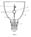
- FIG. 1 schematically a reflector lamp 1 is shown. It has a ceramic discharge vessel 2, which is fastened in a base 3 and has two electrodes 5 in the discharge volume. From the discharge vessel penetrate passages 7. At the base a reflector 4 is fixed, in which the discharge vessel is arranged axially. the discharge volume includes a filling, typically with metal halides and mercury.
- FIG. 2 shows the discharge vessel 2, which is made essentially of Al 2 O 3 , and which has a bulbous central part 8, is housed in the electrodes and a filling with metal halides.
- Capillaries 10 are attached integrally to the central part.
- Mo-pins or multi-part bushings executed as known per se, led to which the shaft of the electrode is welded in each case. It is essential, however, that the rear end of the implementation is a Mo-pin. It has a diameter of typically 1 mm.
- the capillary 10 is followed by a cermet tube 15 of typically 50 layers of film as the adaptation part.
- the films are typically of different thicknesses in a range of 10 to 100 microns, with the possible exception of the first and last films, each of which may be up to 200 to 300 microns thick.
- a high-temperature solder 16 is introduced between capillary and cermet tube.
- a cap 17 made of molybdenum with angled edge 18 is attached, wherein between the cermet tube and cover a platinum solder 19 is introduced for sealing.
- the cap 17 is a Mo sheet having a thickness of typically 200 to 500 ⁇ m.
- the cap 17 is welded to the passage 11, which is passed through a central bore 20 of the cap.
- the cover cap is preferably bulged inwards (21).
- a gap of 50 to 100 ⁇ m width remains between the Mo feedthrough 11 and the capillary 10. The same applies to the gap between the cermet tube 15 and the Mo bushing 11.
- Typical fillings for such lamps are, for example, in EP-A 587 238 described.
- this structure is with axial adaptation part in FIG. 3 shown very schematically.
- the proportion of Mo in the first, the capillary-facing layer is 0 to 15 vol .-% and in the last layer 85 to 100 vol .-%, the rest is possibly Al 2 O 3 . In between, for example, 30 to 100 layers, each about 10 to 100 microns thick, with the layer thicknesses alternate.
- the proportion of Mo is constant in the layers of each component A and B.
- the bushing is preferably a pin, in particular made of Mo. Its diameter is preferably 0.4 to 0.9 mm. But it can also be a pipe, for example, by which the discharge volume can be filled directly, as known per se.
- the individual layers of the films are preferably cast from pastes having a thickness of up to 150 ⁇ m.
- the paste consists of ceramic or metallic powder or mixtures thereof, plus a polymer, plasticizer and solvent, as known per se. This results in green films of polymer-bound Mo-based and A1203-based powder mass.
- FIGS. 4 and 5 show a radially structured adaptation part. It is a cylindrical tube 21, which attaches directly to the passage 22 from Mo. Outside, the tube 21 is bounded by the capillary 23. The tube 21 is sintered directly between passage 22 and capillary 23. The tube 21 consists of typically 30 layers. In this case, layers 25 of a component A alternate with layers 26 of a component B. Component A has a thermal expansion coefficient just below that of A1203 and component B has a coefficient of thermal expansion just above that of Mo. Both thus lie between the thermal expansion coefficient of the bushing 22 on the one hand and the capillary 23 on the other.
- component A has a coefficient of thermal expansion just above that of A1203 and component B has a coefficient of thermal expansion just below that of Mo.
- the layer thickness of the first, innermost layer 25 is relatively large (90 ⁇ m), the layer thickness of the next following first layer 26 is relatively small (10 ⁇ m).
- the thickness of the next following layer 25 is slightly smaller than that of the first layer 25, namely about 80 microns.
- the layer thickness of the next second layer 26 is slightly thicker than that of the first layer 26, namely approximately 20 ⁇ m. In this way, the layer thickness of the component A continuously decreases toward the outside, while the layer thickness of the component B continuously increases towards the outside. In the last two outermost layers, it is then that the last outermost layer 25 is about 10 microns thick, while the last outermost layer 26 is about 90 microns thick.
- FIG. 5 shows a discharge vessel 30 in cross section.
- the radial adaptation part is a straight cut cylindrical tube.
- FIG. 6 shows a further embodiment, a basically similar configuration of a discharge vessel 30.
- the radial adjustment member 31 is a cylindrical tube, the inner, the discharge facing end face 32 is concave.
- the pin 35 of the implementation is concavely arched, at least in a partial section, so that it fits together with the curvature of the adaptation part. In this way, the end face can be optimally adapted to the geometry of the discharge vessel, which is particularly important for the formation or suppression of unwanted standing waves in resonance mode.
- the cermet part with its layers is designed as an Archimedean spiral, wherein the layer thickness refers to a cross section.
- the cermet part is suitably pressed at the end.
- FIG. 7 the cross-section through a capillary is shown.
- the adaptation part here consists of the components A, B and C, where A and B are the components FIG. 4 correspond.
- a layer 60 of MgO is in each case provided as component C, the layer thickness being constant in each case and being approximately 5 ⁇ m.
- the formal layer sequence is ABC or, for example, ACB.
- the coefficients of thermal expansion of the layers A and B can also lie outside the range of the thermal expansion coefficients of the components A and B, but should preferably deviate from this at most 10%.
- a metal-containing cermet in addition to metals such as Mo or W, in particular a metal-containing cermet, as known per se, is suitable as a procedure.
- the implementation thus preferably consists of metallic Mo or W or contains them predominantly, be it as a cermet or as a coated or doped material, the corresponding material of the matching layer comprising Mo powder or W powder in a proportion of at least 85% by volume ,
Landscapes
- Engineering & Computer Science (AREA)
- Manufacturing & Machinery (AREA)
- Vessels And Coating Films For Discharge Lamps (AREA)
Claims (11)
- Lampe à décharge haute pression avec une enceinte de décharge (2) en céramique et un axe longitudinal, dans laquelle au moins une électrode (5) est guidée hors de l'enceinte de décharge (2) au moyen d'une traversée (22) contenant du métal, ladite traversée étant reliée à une extrémité (23) de l'enceinte de décharge via une pièce d'adaptation (21) contenant un cermet, ladite pièce d'adaptation étant de forme tubulaire et constituée, à l'exception éventuellement d'une première et dernière couche de recouvrement, de différentes couches (25, 26) de composition variable où au moins deux matériaux A et B constituent à chaque fois plusieurs couches de la pièce d'adaptation, ces matériaux étant tels que leur coefficient de dilatation thermique se situe entre celui de la traversée et celui de l'extrémité de l'enceinte de décharge ou au maximum de 10 % en dehors de cette fourchette, l'épaisseur de chaque couche étant faible de manière à empêcher l'apparition de contraintes de cisaillement et les couches de même matériau ayant des épaisseurs variables, caractérisée en ce que les épaisseurs des couches de même type croissent ou décroissent de façon monotone, les épaisseurs du matériau A et celles du matériau B évoluant en sens inverse d'un maximum vers un minimum.
- Lampe à décharge haute pression selon la revendication 1, caractérisée en ce que la pièce d'adaptation est stratifiée dans le sens radial.
- Lampe à décharge haute pression selon la revendication 1, caractérisée en ce que la pièce d'adaptation est stratifiée dans le sens axial.
- Lampe à décharge haute pression selon la revendication 1, caractérisée en ce que les différentes couches de la pièce d'adaptation, à l'exception de la première et dernière couche de recouvrement, ont une épaisseur comprise entre 1 et 200 µm, de préférence entre 5 et 150 µm.
- Lampe à décharge haute pression selon la revendication 1, caractérisée en ce que l'épaisseur de couche de chaque paire de couches, dont l'une est en matériau A et l'autre en matériau B, est sensiblement la même.
- Lampe à décharge haute pression selon la revendication 1, caractérisée en ce que la traversée est constituée de Mo ou de W ou en contient principalement, le matériau correspondant de la première couche placée en regard de la traversée de la pièce d'adaptation comprenant du Mo ou du W en poudre dans une proportion au moins égale à 85 % du volume.
- Lampe à décharge haute pression selon la revendication 1, caractérisée en ce que l'enceinte de décharge est constituée d'une céramique oxydique, le matériau correspondant de la première couche placée en regard de l'extrémité de l'enceinte de décharge de la pièce d'adaptation comprenant une poudre de la céramique oxydique dans une proportion au moins égale à 85 % du volume.
- Lampe à décharge haute pression selon la revendication 1, caractérisée en ce que la pièce d'adaptation contient un autre matériau C, de manière à avoir la succession de couches ABC.
- Lampe à décharge haute pression selon la revendication 2, caractérisée en ce que les couches sont réalisées à la manière d'une spirale d'Archimède, l'épaisseur de couche se référant à une coupe transversale dans le sens radial vu du centre.
- Procédé de fabrication d'une pièce d'adaptation tubulaire pour une lampe à décharge haute pression selon la revendication 1, caractérisé par les étapes suivantes :a) fabrication de deux types A et B de feuilles avec une épaisseur de couche variable ne dépassant pas 200 µm, chacune formée d'un cermet composé de Mo ou W et Al2O3 ;b) empilage et laminage d'un paquet d'au moins 30 feuilles, en utilisant successivement une feuille de type A et une feuille de type B, l'épaisseur de couche des types A et B évoluant en sens inverse d'un maximum vers un minimum ;c) découpage de pièces tubulaires dans le produit laminé, pièces qui ont ainsi le long de leur axe longitudinal ou transversal, successivement, une teneur différente en Mo ou W.
- Procédé selon la revendication 10, caractérisé en ce que l'on ajoute à l'étape b) un autre matériau C que l'on insère sous forme de feuille entre les couches AB ou que l'on dépose sur l'une des couches A ou B.
Applications Claiming Priority (2)
| Application Number | Priority Date | Filing Date | Title |
|---|---|---|---|
| DE102009008636A DE102009008636A1 (de) | 2009-02-12 | 2009-02-12 | Hochdruckentladungslampe |
| PCT/EP2010/051254 WO2010091980A1 (fr) | 2009-02-12 | 2010-02-02 | Lampe à décharge à haute pression |
Publications (3)
| Publication Number | Publication Date |
|---|---|
| EP2396802A1 EP2396802A1 (fr) | 2011-12-21 |
| EP2396802B1 true EP2396802B1 (fr) | 2013-01-02 |
| EP2396802B8 EP2396802B8 (fr) | 2013-03-06 |
Family
ID=42008524
Family Applications (1)
| Application Number | Title | Priority Date | Filing Date |
|---|---|---|---|
| EP10702132A Not-in-force EP2396802B8 (fr) | 2009-02-12 | 2010-02-02 | Lampe à décharge à haute pression |
Country Status (6)
| Country | Link |
|---|---|
| US (1) | US8390195B2 (fr) |
| EP (1) | EP2396802B8 (fr) |
| JP (1) | JP2012517680A (fr) |
| CN (1) | CN102318031B (fr) |
| DE (1) | DE102009008636A1 (fr) |
| WO (1) | WO2010091980A1 (fr) |
Family Cites Families (16)
| Publication number | Priority date | Publication date | Assignee | Title |
|---|---|---|---|---|
| US5742123A (en) | 1992-07-09 | 1998-04-21 | Toto Ltd. | Sealing structure for light-emitting bulb assembly and method of manufacturing same |
| EP0587238B1 (fr) | 1992-09-08 | 2000-07-19 | Koninklijke Philips Electronics N.V. | Lampe à décharge à haute pression |
| US6020685A (en) | 1997-06-27 | 2000-02-01 | Osram Sylvania Inc. | Lamp with radially graded cermet feedthrough assembly |
| US5861714A (en) * | 1997-06-27 | 1999-01-19 | Osram Sylvania Inc. | Ceramic envelope device, lamp with such a device, and method of manufacture of such devices |
| JP3460537B2 (ja) * | 1997-10-06 | 2003-10-27 | ウシオ電機株式会社 | 傾斜機能材料 |
| JP3628854B2 (ja) * | 1997-11-14 | 2005-03-16 | 日本碍子株式会社 | 高圧放電灯及びその製造方法 |
| JPH11176333A (ja) * | 1997-12-09 | 1999-07-02 | Ushio Inc | 孔を有する傾斜機能材料の製造方法、傾斜機能材料/金属複合体の製造方法および傾斜機能材料製管球用電気導入体の製造方法 |
| US6375533B1 (en) * | 1998-03-05 | 2002-04-23 | Ushiodenki Kabushiki Kaisha | Electricity lead-in body for bulb and method for manufacturing the same |
| JP2002088405A (ja) * | 2000-07-13 | 2002-03-27 | Toshiba Corp | 傾斜機能材料、その製造法およびその材料を用いた封入部材、放電ランプ |
| US6863586B2 (en) | 2001-10-17 | 2005-03-08 | Matsushita Electric Industrial Co., Ltd. | Manufacturing method for a sealing plug used in sealing an arc tube, sealing plug, and discharge lamp |
| JP3669359B2 (ja) * | 2002-11-01 | 2005-07-06 | 東陶機器株式会社 | 傾斜機能材料の製造方法 |
| JP2004300546A (ja) * | 2003-03-31 | 2004-10-28 | Toshiba Corp | ランプ用傾斜機能材料及びその製造方法 |
| CN1881526A (zh) * | 2005-06-14 | 2006-12-20 | 东芝照明技术株式会社 | 高压放电灯、高压放电灯点灯装置以及照明装置 |
| KR20060130506A (ko) | 2005-06-14 | 2006-12-19 | 도시바 라이텍쿠 가부시키가이샤 | 고압 방전램프, 고압 방전램프 점등장치 및 조명장치 |
| US7378799B2 (en) * | 2005-11-29 | 2008-05-27 | General Electric Company | High intensity discharge lamp having compliant seal |
| DE102007044629A1 (de) * | 2007-09-19 | 2009-04-02 | Osram Gesellschaft mit beschränkter Haftung | Hochdruckentladungslampe |
-
2009
- 2009-02-12 DE DE102009008636A patent/DE102009008636A1/de not_active Withdrawn
-
2010
- 2010-02-02 WO PCT/EP2010/051254 patent/WO2010091980A1/fr not_active Ceased
- 2010-02-02 CN CN201080007727.2A patent/CN102318031B/zh not_active Expired - Fee Related
- 2010-02-02 EP EP10702132A patent/EP2396802B8/fr not_active Not-in-force
- 2010-02-02 JP JP2011549515A patent/JP2012517680A/ja active Pending
- 2010-02-02 US US13/201,225 patent/US8390195B2/en not_active Expired - Fee Related
Also Published As
| Publication number | Publication date |
|---|---|
| US20110291557A1 (en) | 2011-12-01 |
| CN102318031B (zh) | 2014-12-10 |
| US8390195B2 (en) | 2013-03-05 |
| JP2012517680A (ja) | 2012-08-02 |
| DE102009008636A1 (de) | 2010-08-19 |
| CN102318031A (zh) | 2012-01-11 |
| EP2396802A1 (fr) | 2011-12-21 |
| EP2396802B8 (fr) | 2013-03-06 |
| WO2010091980A1 (fr) | 2010-08-19 |
Similar Documents
| Publication | Publication Date | Title |
|---|---|---|
| EP0528427B1 (fr) | Lampe à décharge à haute pression | |
| DE69402848T2 (de) | Keramisches entladungsgefäss und verfahren zu dessen herstellung | |
| EP0652586B1 (fr) | Lampe à décharge à halogénure de métal avec récipient de décharge en céramique et son procédé de fabrication | |
| DE19749908A1 (de) | Elektrodenbauteil für Entladungslampen | |
| EP0887840B1 (fr) | Lampe à halogénure métallique avec enveloppe céramique | |
| EP2020018B1 (fr) | Lampe à décharge à haute pression | |
| EP0602529A2 (fr) | Lampe de décharge à haute pression ayant un récipient céramique de décharge | |
| DE69920373T2 (de) | Stromzuführungskörper für birne und verfahren zu seiner herstellung | |
| EP0573880B1 (fr) | Lampe à décharge haute pression | |
| DE69921901T2 (de) | Cermet und keramische Entladungslampe | |
| WO2010069678A2 (fr) | Enceinte à décharge céramique pour lampe à décharge haute pression | |
| EP2188828B1 (fr) | Lampe à décharge haute pression | |
| EP2396802B1 (fr) | Lampe à décharge à haute pression | |
| DE19908688A1 (de) | Metallhalogenidlampe mit keramischem Entladungsgefäß | |
| DE69825035T2 (de) | Hochdruck-Entladungslampe | |
| EP1730766A2 (fr) | Systeme d'electrodes pour lampe a decharge gazeuse haute pression | |
| DE102007020067B4 (de) | Verfahren zur Herstellung einer Molybdänfolie für den Lampenbau und Molybdänfolie sowie Lampe mit Molybdänfolie | |
| EP1351278B1 (fr) | Lampe à halogénure métallique avec enveloppe céramique | |
| DE60100556T2 (de) | Entladungslampe | |
| DE102004002455A1 (de) | Lampe mit fixiertem Glasbauteil | |
| DE20210400U1 (de) | Elektrodensystem für eine Metallhalogenidlampe und zugehörige Lampe | |
| EP2153457A2 (fr) | Lampe à décharge haute pression | |
| DE202013008473U1 (de) | Gasentladungsröhre mit Zündhilfe | |
| DE19529465A1 (de) | Hochdruckentladungslampe | |
| EP1958239A2 (fr) | Lampe a decharge haute pression comprenant une enceinte de decharge ceramique |
Legal Events
| Date | Code | Title | Description |
|---|---|---|---|
| PUAI | Public reference made under article 153(3) epc to a published international application that has entered the european phase |
Free format text: ORIGINAL CODE: 0009012 |
|
| 17P | Request for examination filed |
Effective date: 20110707 |
|
| AK | Designated contracting states |
Kind code of ref document: A1 Designated state(s): AT BE BG CH CY CZ DE DK EE ES FI FR GB GR HR HU IE IS IT LI LT LU LV MC MK MT NL NO PL PT RO SE SI SK SM TR |
|
| DAX | Request for extension of the european patent (deleted) | ||
| RAP1 | Party data changed (applicant data changed or rights of an application transferred) |
Owner name: OSRAM AG |
|
| GRAP | Despatch of communication of intention to grant a patent |
Free format text: ORIGINAL CODE: EPIDOSNIGR1 |
|
| GRAS | Grant fee paid |
Free format text: ORIGINAL CODE: EPIDOSNIGR3 |
|
| GRAA | (expected) grant |
Free format text: ORIGINAL CODE: 0009210 |
|
| AK | Designated contracting states |
Kind code of ref document: B1 Designated state(s): AT BE BG CH CY CZ DE DK EE ES FI FR GB GR HR HU IE IS IT LI LT LU LV MC MK MT NL NO PL PT RO SE SI SK SM TR |
|
| REG | Reference to a national code |
Ref country code: GB Ref legal event code: FG4D Free format text: NOT ENGLISH |
|
| REG | Reference to a national code |
Ref country code: AT Ref legal event code: REF Ref document number: 592017 Country of ref document: AT Kind code of ref document: T Effective date: 20130115 Ref country code: CH Ref legal event code: EP |
|
| RAP2 | Party data changed (patent owner data changed or rights of a patent transferred) |
Owner name: OSRAM GMBH |
|
| REG | Reference to a national code |
Ref country code: IE Ref legal event code: FG4D Free format text: LANGUAGE OF EP DOCUMENT: GERMAN |
|
| REG | Reference to a national code |
Ref country code: DE Ref legal event code: R096 Ref document number: 502010002020 Country of ref document: DE Effective date: 20130228 |
|
| REG | Reference to a national code |
Ref country code: AT Ref legal event code: HC Ref document number: 592017 Country of ref document: AT Kind code of ref document: T Owner name: OSRAM GMBH, DE Effective date: 20130220 |
|
| RAP2 | Party data changed (patent owner data changed or rights of a patent transferred) |
Owner name: OSRAM GMBH |
|
| REG | Reference to a national code |
Ref country code: NL Ref legal event code: VDEP Effective date: 20130102 |
|
| PG25 | Lapsed in a contracting state [announced via postgrant information from national office to epo] |
Ref country code: SI Free format text: LAPSE BECAUSE OF FAILURE TO SUBMIT A TRANSLATION OF THE DESCRIPTION OR TO PAY THE FEE WITHIN THE PRESCRIBED TIME-LIMIT Effective date: 20130102 |
|
| REG | Reference to a national code |
Ref country code: LT Ref legal event code: MG4D |
|
| PG25 | Lapsed in a contracting state [announced via postgrant information from national office to epo] |
Ref country code: SE Free format text: LAPSE BECAUSE OF FAILURE TO SUBMIT A TRANSLATION OF THE DESCRIPTION OR TO PAY THE FEE WITHIN THE PRESCRIBED TIME-LIMIT Effective date: 20130102 Ref country code: LT Free format text: LAPSE BECAUSE OF FAILURE TO SUBMIT A TRANSLATION OF THE DESCRIPTION OR TO PAY THE FEE WITHIN THE PRESCRIBED TIME-LIMIT Effective date: 20130102 Ref country code: NO Free format text: LAPSE BECAUSE OF FAILURE TO SUBMIT A TRANSLATION OF THE DESCRIPTION OR TO PAY THE FEE WITHIN THE PRESCRIBED TIME-LIMIT Effective date: 20130402 Ref country code: IS Free format text: LAPSE BECAUSE OF FAILURE TO SUBMIT A TRANSLATION OF THE DESCRIPTION OR TO PAY THE FEE WITHIN THE PRESCRIBED TIME-LIMIT Effective date: 20130502 Ref country code: CZ Free format text: LAPSE BECAUSE OF FAILURE TO SUBMIT A TRANSLATION OF THE DESCRIPTION OR TO PAY THE FEE WITHIN THE PRESCRIBED TIME-LIMIT Effective date: 20130102 Ref country code: BG Free format text: LAPSE BECAUSE OF FAILURE TO SUBMIT A TRANSLATION OF THE DESCRIPTION OR TO PAY THE FEE WITHIN THE PRESCRIBED TIME-LIMIT Effective date: 20130402 Ref country code: ES Free format text: LAPSE BECAUSE OF FAILURE TO SUBMIT A TRANSLATION OF THE DESCRIPTION OR TO PAY THE FEE WITHIN THE PRESCRIBED TIME-LIMIT Effective date: 20130413 |
|
| PG25 | Lapsed in a contracting state [announced via postgrant information from national office to epo] |
Ref country code: PT Free format text: LAPSE BECAUSE OF FAILURE TO SUBMIT A TRANSLATION OF THE DESCRIPTION OR TO PAY THE FEE WITHIN THE PRESCRIBED TIME-LIMIT Effective date: 20130502 Ref country code: PL Free format text: LAPSE BECAUSE OF FAILURE TO SUBMIT A TRANSLATION OF THE DESCRIPTION OR TO PAY THE FEE WITHIN THE PRESCRIBED TIME-LIMIT Effective date: 20130102 Ref country code: GR Free format text: LAPSE BECAUSE OF FAILURE TO SUBMIT A TRANSLATION OF THE DESCRIPTION OR TO PAY THE FEE WITHIN THE PRESCRIBED TIME-LIMIT Effective date: 20130403 Ref country code: FI Free format text: LAPSE BECAUSE OF FAILURE TO SUBMIT A TRANSLATION OF THE DESCRIPTION OR TO PAY THE FEE WITHIN THE PRESCRIBED TIME-LIMIT Effective date: 20130102 Ref country code: LV Free format text: LAPSE BECAUSE OF FAILURE TO SUBMIT A TRANSLATION OF THE DESCRIPTION OR TO PAY THE FEE WITHIN THE PRESCRIBED TIME-LIMIT Effective date: 20130102 Ref country code: NL Free format text: LAPSE BECAUSE OF FAILURE TO SUBMIT A TRANSLATION OF THE DESCRIPTION OR TO PAY THE FEE WITHIN THE PRESCRIBED TIME-LIMIT Effective date: 20130102 |
|
| BERE | Be: lapsed |
Owner name: OSRAM A.G. Effective date: 20130228 |
|
| PG25 | Lapsed in a contracting state [announced via postgrant information from national office to epo] |
Ref country code: MC Free format text: LAPSE BECAUSE OF NON-PAYMENT OF DUE FEES Effective date: 20130228 Ref country code: HR Free format text: LAPSE BECAUSE OF FAILURE TO SUBMIT A TRANSLATION OF THE DESCRIPTION OR TO PAY THE FEE WITHIN THE PRESCRIBED TIME-LIMIT Effective date: 20130102 |
|
| REG | Reference to a national code |
Ref country code: DE Ref legal event code: R081 Ref document number: 502010002020 Country of ref document: DE Owner name: OSRAM GMBH, DE Free format text: FORMER OWNER: OSRAM GMBH, 81543 MUENCHEN, DE Effective date: 20130829 Ref country code: DE Ref legal event code: R081 Ref document number: 502010002020 Country of ref document: DE Owner name: OSRAM GMBH, DE Free format text: FORMER OWNER: OSRAM AG, 81543 MUENCHEN, DE Effective date: 20130204 Ref country code: DE Ref legal event code: R081 Ref document number: 502010002020 Country of ref document: DE Owner name: LEDVANCE GMBH, DE Free format text: FORMER OWNER: OSRAM AG, 81543 MUENCHEN, DE Effective date: 20130204 Ref country code: DE Ref legal event code: R081 Ref document number: 502010002020 Country of ref document: DE Owner name: LEDVANCE GMBH, DE Free format text: FORMER OWNER: OSRAM GMBH, 81543 MUENCHEN, DE Effective date: 20130829 |
|
| PG25 | Lapsed in a contracting state [announced via postgrant information from national office to epo] |
Ref country code: EE Free format text: LAPSE BECAUSE OF FAILURE TO SUBMIT A TRANSLATION OF THE DESCRIPTION OR TO PAY THE FEE WITHIN THE PRESCRIBED TIME-LIMIT Effective date: 20130102 Ref country code: RO Free format text: LAPSE BECAUSE OF FAILURE TO SUBMIT A TRANSLATION OF THE DESCRIPTION OR TO PAY THE FEE WITHIN THE PRESCRIBED TIME-LIMIT Effective date: 20130102 Ref country code: DK Free format text: LAPSE BECAUSE OF FAILURE TO SUBMIT A TRANSLATION OF THE DESCRIPTION OR TO PAY THE FEE WITHIN THE PRESCRIBED TIME-LIMIT Effective date: 20130102 Ref country code: SK Free format text: LAPSE BECAUSE OF FAILURE TO SUBMIT A TRANSLATION OF THE DESCRIPTION OR TO PAY THE FEE WITHIN THE PRESCRIBED TIME-LIMIT Effective date: 20130102 |
|
| PLBE | No opposition filed within time limit |
Free format text: ORIGINAL CODE: 0009261 |
|
| STAA | Information on the status of an ep patent application or granted ep patent |
Free format text: STATUS: NO OPPOSITION FILED WITHIN TIME LIMIT |
|
| REG | Reference to a national code |
Ref country code: FR Ref legal event code: ST Effective date: 20131031 |
|
| PG25 | Lapsed in a contracting state [announced via postgrant information from national office to epo] |
Ref country code: CY Free format text: LAPSE BECAUSE OF FAILURE TO SUBMIT A TRANSLATION OF THE DESCRIPTION OR TO PAY THE FEE WITHIN THE PRESCRIBED TIME-LIMIT Effective date: 20130102 |
|
| REG | Reference to a national code |
Ref country code: IE Ref legal event code: MM4A |
|
| 26N | No opposition filed |
Effective date: 20131003 |
|
| PG25 | Lapsed in a contracting state [announced via postgrant information from national office to epo] |
Ref country code: IT Free format text: LAPSE BECAUSE OF FAILURE TO SUBMIT A TRANSLATION OF THE DESCRIPTION OR TO PAY THE FEE WITHIN THE PRESCRIBED TIME-LIMIT Effective date: 20130102 |
|
| REG | Reference to a national code |
Ref country code: DE Ref legal event code: R097 Ref document number: 502010002020 Country of ref document: DE Effective date: 20131003 |
|
| REG | Reference to a national code |
Ref country code: HU Ref legal event code: AG4A Ref document number: E018027 Country of ref document: HU |
|
| PG25 | Lapsed in a contracting state [announced via postgrant information from national office to epo] |
Ref country code: FR Free format text: LAPSE BECAUSE OF NON-PAYMENT OF DUE FEES Effective date: 20130304 Ref country code: BE Free format text: LAPSE BECAUSE OF NON-PAYMENT OF DUE FEES Effective date: 20130228 Ref country code: IE Free format text: LAPSE BECAUSE OF NON-PAYMENT OF DUE FEES Effective date: 20130202 |
|
| PGFP | Annual fee paid to national office [announced via postgrant information from national office to epo] |
Ref country code: HU Payment date: 20130218 Year of fee payment: 4 |
|
| PG25 | Lapsed in a contracting state [announced via postgrant information from national office to epo] |
Ref country code: MT Free format text: LAPSE BECAUSE OF FAILURE TO SUBMIT A TRANSLATION OF THE DESCRIPTION OR TO PAY THE FEE WITHIN THE PRESCRIBED TIME-LIMIT Effective date: 20130102 |
|
| REG | Reference to a national code |
Ref country code: CH Ref legal event code: PL |
|
| GBPC | Gb: european patent ceased through non-payment of renewal fee |
Effective date: 20140202 |
|
| PG25 | Lapsed in a contracting state [announced via postgrant information from national office to epo] |
Ref country code: CH Free format text: LAPSE BECAUSE OF NON-PAYMENT OF DUE FEES Effective date: 20140228 Ref country code: LI Free format text: LAPSE BECAUSE OF NON-PAYMENT OF DUE FEES Effective date: 20140228 |
|
| PG25 | Lapsed in a contracting state [announced via postgrant information from national office to epo] |
Ref country code: HU Free format text: LAPSE BECAUSE OF NON-PAYMENT OF DUE FEES Effective date: 20140203 |
|
| PG25 | Lapsed in a contracting state [announced via postgrant information from national office to epo] |
Ref country code: GB Free format text: LAPSE BECAUSE OF NON-PAYMENT OF DUE FEES Effective date: 20140202 |
|
| PG25 | Lapsed in a contracting state [announced via postgrant information from national office to epo] |
Ref country code: SM Free format text: LAPSE BECAUSE OF FAILURE TO SUBMIT A TRANSLATION OF THE DESCRIPTION OR TO PAY THE FEE WITHIN THE PRESCRIBED TIME-LIMIT Effective date: 20130102 |
|
| PG25 | Lapsed in a contracting state [announced via postgrant information from national office to epo] |
Ref country code: TR Free format text: LAPSE BECAUSE OF FAILURE TO SUBMIT A TRANSLATION OF THE DESCRIPTION OR TO PAY THE FEE WITHIN THE PRESCRIBED TIME-LIMIT Effective date: 20130102 |
|
| PG25 | Lapsed in a contracting state [announced via postgrant information from national office to epo] |
Ref country code: MK Free format text: LAPSE BECAUSE OF FAILURE TO SUBMIT A TRANSLATION OF THE DESCRIPTION OR TO PAY THE FEE WITHIN THE PRESCRIBED TIME-LIMIT Effective date: 20130102 Ref country code: LU Free format text: LAPSE BECAUSE OF NON-PAYMENT OF DUE FEES Effective date: 20130202 |
|
| REG | Reference to a national code |
Ref country code: AT Ref legal event code: MM01 Ref document number: 592017 Country of ref document: AT Kind code of ref document: T Effective date: 20150202 |
|
| PG25 | Lapsed in a contracting state [announced via postgrant information from national office to epo] |
Ref country code: AT Free format text: LAPSE BECAUSE OF NON-PAYMENT OF DUE FEES Effective date: 20150202 |
|
| REG | Reference to a national code |
Ref country code: DE Ref legal event code: R081 Ref document number: 502010002020 Country of ref document: DE Owner name: LEDVANCE GMBH, DE Free format text: FORMER OWNER: OSRAM GMBH, 80807 MUENCHEN, DE |
|
| PGFP | Annual fee paid to national office [announced via postgrant information from national office to epo] |
Ref country code: DE Payment date: 20170222 Year of fee payment: 8 |
|
| REG | Reference to a national code |
Ref country code: DE Ref legal event code: R119 Ref document number: 502010002020 Country of ref document: DE |
|
| PG25 | Lapsed in a contracting state [announced via postgrant information from national office to epo] |
Ref country code: DE Free format text: LAPSE BECAUSE OF NON-PAYMENT OF DUE FEES Effective date: 20180901 |