EP2397209B1 - Dispositif de filtration et son procédé d'operation - Google Patents
Dispositif de filtration et son procédé d'operation Download PDFInfo
- Publication number
- EP2397209B1 EP2397209B1 EP10741303.1A EP10741303A EP2397209B1 EP 2397209 B1 EP2397209 B1 EP 2397209B1 EP 10741303 A EP10741303 A EP 10741303A EP 2397209 B1 EP2397209 B1 EP 2397209B1
- Authority
- EP
- European Patent Office
- Prior art keywords
- filtering
- fluid
- supplying
- passage
- filtrate water
- Prior art date
- Legal status (The legal status is an assumption and is not a legal conclusion. Google has not performed a legal analysis and makes no representation as to the accuracy of the status listed.)
- Not-in-force
Links
Images

Classifications
-
- B—PERFORMING OPERATIONS; TRANSPORTING
- B01—PHYSICAL OR CHEMICAL PROCESSES OR APPARATUS IN GENERAL
- B01D—SEPARATION
- B01D29/00—Filters with filtering elements stationary during filtration, e.g. pressure or suction filters, not covered by groups B01D24/00 - B01D27/00; Filtering elements therefor
- B01D29/11—Filters with filtering elements stationary during filtration, e.g. pressure or suction filters, not covered by groups B01D24/00 - B01D27/00; Filtering elements therefor with bag, cage, hose, tube, sleeve or like filtering elements
-
- B—PERFORMING OPERATIONS; TRANSPORTING
- B01—PHYSICAL OR CHEMICAL PROCESSES OR APPARATUS IN GENERAL
- B01D—SEPARATION
- B01D29/00—Filters with filtering elements stationary during filtration, e.g. pressure or suction filters, not covered by groups B01D24/00 - B01D27/00; Filtering elements therefor
- B01D29/62—Regenerating the filter material in the filter
- B01D29/66—Regenerating the filter material in the filter by flushing, e.g. counter-current air-bumps
-
- B—PERFORMING OPERATIONS; TRANSPORTING
- B01—PHYSICAL OR CHEMICAL PROCESSES OR APPARATUS IN GENERAL
- B01D—SEPARATION
- B01D61/00—Processes of separation using semi-permeable membranes, e.g. dialysis, osmosis or ultrafiltration; Apparatus, accessories or auxiliary operations specially adapted therefor
- B01D61/02—Reverse osmosis; Hyperfiltration ; Nanofiltration
- B01D61/025—Reverse osmosis; Hyperfiltration
-
- B—PERFORMING OPERATIONS; TRANSPORTING
- B01—PHYSICAL OR CHEMICAL PROCESSES OR APPARATUS IN GENERAL
- B01D—SEPARATION
- B01D61/00—Processes of separation using semi-permeable membranes, e.g. dialysis, osmosis or ultrafiltration; Apparatus, accessories or auxiliary operations specially adapted therefor
- B01D61/02—Reverse osmosis; Hyperfiltration ; Nanofiltration
- B01D61/04—Feed pretreatment
-
- B—PERFORMING OPERATIONS; TRANSPORTING
- B01—PHYSICAL OR CHEMICAL PROCESSES OR APPARATUS IN GENERAL
- B01D—SEPARATION
- B01D61/00—Processes of separation using semi-permeable membranes, e.g. dialysis, osmosis or ultrafiltration; Apparatus, accessories or auxiliary operations specially adapted therefor
- B01D61/14—Ultrafiltration; Microfiltration
- B01D61/145—Ultrafiltration
-
- B—PERFORMING OPERATIONS; TRANSPORTING
- B01—PHYSICAL OR CHEMICAL PROCESSES OR APPARATUS IN GENERAL
- B01D—SEPARATION
- B01D61/00—Processes of separation using semi-permeable membranes, e.g. dialysis, osmosis or ultrafiltration; Apparatus, accessories or auxiliary operations specially adapted therefor
- B01D61/14—Ultrafiltration; Microfiltration
- B01D61/16—Feed pretreatment
-
- B—PERFORMING OPERATIONS; TRANSPORTING
- B63—SHIPS OR OTHER WATERBORNE VESSELS; RELATED EQUIPMENT
- B63B—SHIPS OR OTHER WATERBORNE VESSELS; EQUIPMENT FOR SHIPPING
- B63B13/00—Conduits for emptying or ballasting; Self-bailing equipment; Scuppers
-
- C—CHEMISTRY; METALLURGY
- C02—TREATMENT OF WATER, WASTE WATER, SEWAGE, OR SLUDGE
- C02F—TREATMENT OF WATER, WASTE WATER, SEWAGE, OR SLUDGE
- C02F1/00—Treatment of water, waste water, or sewage
- C02F1/001—Processes for the treatment of water whereby the filtration technique is of importance
- C02F1/004—Processes for the treatment of water whereby the filtration technique is of importance using large scale industrial sized filters
-
- C—CHEMISTRY; METALLURGY
- C02—TREATMENT OF WATER, WASTE WATER, SEWAGE, OR SLUDGE
- C02F—TREATMENT OF WATER, WASTE WATER, SEWAGE, OR SLUDGE
- C02F1/00—Treatment of water, waste water, or sewage
- C02F1/44—Treatment of water, waste water, or sewage by dialysis, osmosis or reverse osmosis
-
- B—PERFORMING OPERATIONS; TRANSPORTING
- B01—PHYSICAL OR CHEMICAL PROCESSES OR APPARATUS IN GENERAL
- B01D—SEPARATION
- B01D2311/00—Details relating to membrane separation process operations and control
- B01D2311/04—Specific process operations in the feed stream; Feed pretreatment
-
- B—PERFORMING OPERATIONS; TRANSPORTING
- B01—PHYSICAL OR CHEMICAL PROCESSES OR APPARATUS IN GENERAL
- B01D—SEPARATION
- B01D2311/00—Details relating to membrane separation process operations and control
- B01D2311/16—Flow or flux control
-
- C—CHEMISTRY; METALLURGY
- C02—TREATMENT OF WATER, WASTE WATER, SEWAGE, OR SLUDGE
- C02F—TREATMENT OF WATER, WASTE WATER, SEWAGE, OR SLUDGE
- C02F1/00—Treatment of water, waste water, or sewage
- C02F1/44—Treatment of water, waste water, or sewage by dialysis, osmosis or reverse osmosis
- C02F1/441—Treatment of water, waste water, or sewage by dialysis, osmosis or reverse osmosis by reverse osmosis
-
- C—CHEMISTRY; METALLURGY
- C02—TREATMENT OF WATER, WASTE WATER, SEWAGE, OR SLUDGE
- C02F—TREATMENT OF WATER, WASTE WATER, SEWAGE, OR SLUDGE
- C02F1/00—Treatment of water, waste water, or sewage
- C02F1/44—Treatment of water, waste water, or sewage by dialysis, osmosis or reverse osmosis
- C02F1/444—Treatment of water, waste water, or sewage by dialysis, osmosis or reverse osmosis by ultrafiltration or microfiltration
-
- C—CHEMISTRY; METALLURGY
- C02—TREATMENT OF WATER, WASTE WATER, SEWAGE, OR SLUDGE
- C02F—TREATMENT OF WATER, WASTE WATER, SEWAGE, OR SLUDGE
- C02F2103/00—Nature of the water, waste water, sewage or sludge to be treated
- C02F2103/08—Seawater, e.g. for desalination
-
- C—CHEMISTRY; METALLURGY
- C02—TREATMENT OF WATER, WASTE WATER, SEWAGE, OR SLUDGE
- C02F—TREATMENT OF WATER, WASTE WATER, SEWAGE, OR SLUDGE
- C02F2103/00—Nature of the water, waste water, sewage or sludge to be treated
- C02F2103/42—Nature of the water, waste water, sewage or sludge to be treated from bathing facilities, e.g. swimming pools
-
- C—CHEMISTRY; METALLURGY
- C02—TREATMENT OF WATER, WASTE WATER, SEWAGE, OR SLUDGE
- C02F—TREATMENT OF WATER, WASTE WATER, SEWAGE, OR SLUDGE
- C02F2209/00—Controlling or monitoring parameters in water treatment
- C02F2209/005—Processes using a programmable logic controller [PLC]
-
- C—CHEMISTRY; METALLURGY
- C02—TREATMENT OF WATER, WASTE WATER, SEWAGE, OR SLUDGE
- C02F—TREATMENT OF WATER, WASTE WATER, SEWAGE, OR SLUDGE
- C02F2209/00—Controlling or monitoring parameters in water treatment
- C02F2209/40—Liquid flow rate
-
- Y—GENERAL TAGGING OF NEW TECHNOLOGICAL DEVELOPMENTS; GENERAL TAGGING OF CROSS-SECTIONAL TECHNOLOGIES SPANNING OVER SEVERAL SECTIONS OF THE IPC; TECHNICAL SUBJECTS COVERED BY FORMER USPC CROSS-REFERENCE ART COLLECTIONS [XRACs] AND DIGESTS
- Y02—TECHNOLOGIES OR APPLICATIONS FOR MITIGATION OR ADAPTATION AGAINST CLIMATE CHANGE
- Y02A—TECHNOLOGIES FOR ADAPTATION TO CLIMATE CHANGE
- Y02A20/00—Water conservation; Efficient water supply; Efficient water use
- Y02A20/124—Water desalination
- Y02A20/131—Reverse-osmosis
Definitions
- the present invention relates to a filtering device for filtering water of a kind used in, for example, pools and spas as it is recirculated or filtering water of a kind used in, for example, in a desalination plant.
- a sand filtering device is employed in circulatory filtration of water used in, for example, a bathtub or a pool.
- the sand filtering device is of such a structure which makes use of a gravel layer and a sand layer deposited thereon, through both of which water is allowed to pass so that finely divided particles suspended in the water can be removed. It has, however, been found that the device itself is bulky in size, thus involving a problem that a relatively large space for installation is required.
- a membrane filtering device in which a membrane made of a synthetic resin of a kind capable of trapping finely divided particles is employed.
- the membrane filtering device is relatively small in size and can, therefore, be installed in a relatively small space; see, for example, JP 2002-096064 A (Patent Document 1).
- the ultrafiltration membrane or the reverse osmosis membrane or the like is employed, but the sand filtering device is often used in the front stage of the ultrafiltration membrane or reverse osmosis membrane.
- WO 2006/108025 A2 discloses a membrane filtration with self-cleaning strainers for pretreatment of wastewater.
- WO 2002/076590 A2 discloses a filtering system with cartridge prefilters.
- the surface filter is a filter capable of trapping foreign matter on a surface of the filtering medium and is used in, for example, a high precision filtration in which the filtering surface area is increased to reduce the filtering resistance so that the amount of trapping the foreign matter can be increased.
- the surface filter can be repeatedly reused if it is backwashed.
- the amount of foreign matter trapped thereby is relatively small and, therefore, the surface filter is not suited for use in filtration of water containing a relatively large amount of contaminants. Also, since the surface filter is expensive, the application thereof is limited.
- the depth filter is a filter of a design in which the foreign matter can be trapped in interstices in the filtering medium. Since the depth filter exhibits a capability of trapping a relatively large amount of foreign matter, it is used also in filtration of water containing a relatively large amount of contaminants. Although as compared with the surface filter the depth filter is relatively inexpensive, backwashing of the depth filter is rather difficult to achieve as compared with that of the surface filter because the foreign matter is trapped in the interstices, not on the surface, of the filtering medium.
- the depth filter is used for filtration after it has been backwashed, it may often occur that ultrafine particles caught somewhere in the interstices of the filtering medium during the backwashing will accumulate immediately after the filtration resumed, resulting in that the filtrate water may be suspended. Since those ultrafine particles have a particle size smaller than a pore size of the depth filter, there should be no problem even if they remain in the filtrate water, but depending on the application, such a suspension will possibly pose a detrimental problem.
- the seawater is treated by means of the reverse osmosis membrane, the sand filtering device is often concurrently used as a pre-filter in order to remove various particulate matters contained in the seawater.
- the sand filtering device may fail to operate properly when they grew up and/or proliferate.
- the present invention has been devised to substantially eliminate the problems and inconveniences inherent in the prior art filtering systems and is intended to provide a filtering device including a filtration unit effective to minimize the initial introduction cost and the maintenance and operation cost, and further compact in structure, effective to suppress suspension of the filtrate water.
- the present invention has an additional object to provide the filtering device of the kind referred to above, which can be used as a substitute of the sand filtering device or as a pre-filter for the sand filtering device thereby to increase the lifetime of the filtering system as a whole. This object is achieved with the features of the claims.
- a filtering device as described includes a primary filtration unit for filtering a raw water, which unit includes a filtering medium and a housing for accommodating the filtering medium.
- the housing referred to above has defined therein a raw water supplying port for supplying the raw water therethrough into the filtering medium, a filtrate water outlet port, a fluid supplying port for supplying a fluid for backwashing therethrough into the filtering medium and a drain port for discharging therethrough the fluid used to backwash the filtering medium and the raw water.
- the filtering medium referred to above includes a depth filter having a pore size within the range of 1 to 25 ⁇ m.
- the filtering device also includes a filtrate supplying passage fluid connected with the filtrate water outlet port, a drain passage fluid connected with the drain port, a communication passage for communicating the filtrate supplying passage with the drain passage and a switching valve for selectively opening or closing the communication passage.
- a gas or a liquid is employed, but the use of the gas is preferred. More preferably, an inert gas such as, for example, air and/or nitrogen is preferred for that fluid. If the pore size is not greater than 1 ⁇ m, clogging will occur and the pressure loss will increase. On the other hand, if the pore size exceeds 25 ⁇ m, suspended matter will become noticeable in the water.
- a liquid medium is prepared by adding particles having a constant diameter, preferably spherical beads of polystyrene or glass, into water in a quantity of 10,000 particle per litter; and then supplied to the depth filter (60 mm in outer diameter, 30 mm in inner diameter and 250 mm in length) under the condition of 25°C at a rate of 1.0 mm 3 /h.
- the number of the particles passed through the depth filter is measured by means of an optical counter to obtain the respective numbers of the particles before the supply across the depth filter and after the discharge from the depth filter.
- the measurement can be accomplished when the liquid medium added with the spherical polystyrene microparticles (10,000 microparticles/liter) is supplied through the depth filter (60 mm in outer diameter, 30 mm in inner diameter and 250 mm in length) under the above described condition.
- the depth filter having a pore size within the range of 1 to 25 ⁇ m since the depth filter having a pore size within the range of 1 to 25 ⁇ m is employed, not only can suspended matter of a noticeable particle size be sufficiently removed, but also the initial introduction cost can be suppressed as compared with that in the use of a surface filter. Also, since the employment of the backwashing is effective to recuperate the filtering capability of the depth filter, the frequency of replacement of the depth filter can advantageously be minimized to thereby suppress the cost incurred in maintenance and operation of the filtering device.
- the filtrate water containing the ultrafine particles accumulated can be discharged to the drain passage by opening the switching valve immediately after the backwashing thereby preventing the suspended or muddy filtrate water to be supplied.
- this filtering device is used as a substitute of the sand filtering device or as a pre-filter for the sand filtering device, deposition of planktons or the like existing in water to the sand filtering device can be prevented to thereby increase the lifetime of the filtering system as a whole.
- the use may be made of a secondary filtration unit for filtering again the filtrate water, which has been filtered by the primary filtration unit, by means of a filtering medium including an ultrafiltration membrane or a reverse osmosis membrane.
- a filtering medium including an ultrafiltration membrane or a reverse osmosis membrane.
- the fluid supplying port and the filtrate water outlet port are preferably the same. According to this construction, the fluid supplying port and the filtrate water outlet port are commonly shared with each other, allowing the structure to be simplified.
- the drain port and the raw water supplying port are preferably the same. According to this construction, the drain port and the raw water supplying port are commonly shared with each other, allowing the structure to be simplified.
- the present invention also provides a method of making a filtrate water with the use of a filtering device of the present invention, which method includes a priming step of discharging the fluid, together with the raw water, through the filtration unit, then through the communication passage and finally through the drain passage in a condition in which the switching valve is opened while the supply of the filtrate water from the filtering medium and the supply of the fluid for backwashing towards the filtering medium are interrupted; a filtering step of supplying the raw water to the primary filtration unit to cause the filtrate water to be transported towards the filtrate water outlet port in a condition in which the discharge of the raw water from the filtering medium and the supply of the fluid for backwashing towards the filtering medium are interrupted; a backwashing step of supplying the fluid for backwashing from a filtrate water side towards the filtering medium and then discharging the fluid from the drain port through the drain passage in a condition in which the supply of the filtrate water is interrupted.
- the backwashing since the backwashing is effective to recuperate the filtering capability of the filtering medium and then to allow it to be reused further, the cost incurred in maintenance and operation can be suppressed. Also, since during the priming step the filtrate water after the backwashing is discharged through the communication passage and then through the drain passage, there is no possibility that the filtrate water may be suspended immediately after the backwashing.
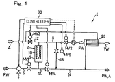
- FIG. 1 schematically illustrates a fluid circuit of a filtering device, including a filtration unit, according to the preferred embodiment of the present invention.
- the filtering device 1 includes a filtration pump 2 for pumping a raw water RW from a water source to the system and a primary filtration unit 4 for filtering the raw water RW so supplied from the water source.
- the primary filtration unit 4 is fluid connected with a raw water passage 5, through which the raw water RW is supplied thereto from the filtration pump 2, a filtrate water supplying passage 8 for discharging a filtrate water FW from the primary filtration unit 4, and a drain passage 14 for discharging the raw water RW within the primary filtration unit 4 together with a compressed air A as will be described later.
- the filtrate water supplying passage 8 is in turn fluid connected with a fluid supplying passage 12 through which the compressed air A is supplied into the primary filtration unit 4.
- the filtrate water supplying passage 8 and the drain passage 14 are fluid communicated with each other through a communication passage 15.
- a communication passage 15 As a matter of course, those passages 5, 8, 12, 14 and 15 referred to above are defined by any known tubes or pipes.
- the primary filtration unit 4 includes a generally or substantially cylindrical housing 9 accommodating therein a depth filter 10 which is a filtering medium forming a filtering membrane.
- a first automatic switching valve MV1 that functions as a flow control valve for regulating the flow of the raw water is disposed on the raw water passage 5; a second automatic switching valve MV2 that functions as a conveyance valve for the filtrate water FW is disposed on the filtrate water supplying passage 8; and a flow meter FI is disposed on a portion of the filtrate water supplying passage 8 downstream of the second automatic switching valve MV2 with respect to the direction of flow of the filtrate water FW.
- a secondary filtration unit 26 having a hollow fiber membrane (not shown) of a pore size not greater than 1 ⁇ m, which is a ultrafiltration membrane, is disposed on a portion of the filtrate water supplying passage 8 downstream of the flow meter FI.
- This secondary filtration unit 26 is used to filter the filtrate water FW, discharged from the first filtration unit 4, to purify or substantially purify the latter highly precisely to thereby provide a treated water TW.
- the filtering membrane used in this secondary filtration unit 26 may not be necessarily limited to the hollow fiber membrane referred to above, but may be employed in the form of any known ultrafiltration membrane.
- a reverse osmosis membrane may be employed in place of the ultrafiltration membrane.
- one or a mixture of medical agents for sterilization may be added to the filtrate water FW then flowing through that portion of the filtrate water supplying passage 8 downstream of the flow meter FI, or the secondary filtration unit 26 may be dispensed with.
- the fluid supplying passage 12 has a third automatic switching valve MV3 disposed thereon, which valve MV3 functions as a compressed air introducing valve, and, on the other hand, the drain passage 14 has a fourth automatic switching valve MV4 disposed thereon so as to function as a drain valve.
- the communication passage 15 referred to previously has a fifth automatic switching valve MV5 disposed thereon, which valve MV5 is used to selectively open or close the communication passage 15.
- the communication passage 15 is branched off from a portion of the filtrate water supplying passage 8 upstream of the second automatic switching valve MV2 with respect to the direction of flow of the filtrate water FW and is fluid connected with a portion of the drain passage 14 downstream of the fourth automatic switching valve MV4.
- the fluid supplying passage 12 has one end fluid connected with an air compressor (not shown) and the opposite end fluid connected with a secondary side of an upper section of the primary filtration unit 4, i.e., a secondary chamber of the primary filtration unit 4.
- the filtration pump 2 and the first to fifth automatic switching valves MV1 to MV5 are driven under the control of a controller 30. Also, the flow meter FI provides an output thereof to the controller 30.
- a pneumatically operated valve, a motor valve, an electromagnetical value, or a manual valve with no controller can be employed.
- the filtering device as a whole can be simplified in structure if the same fluid is used for backwashing the hollow fiber membrane in the secondary filtration unit 26 and also for backwashing the depth filter 10 employed in the primary filtration unit 4. Also, where any existing filtering device of a type including, for example, a sand filtering device and a secondary filtration unit having the backwashing function is available, any existing fluid for backwashing use can be employed when the sand filtering device employed in the existing filtering device is replaced with the primary filtration unit 4 of the type employed in the embodiment as described above.
- the present invention can be applied to such existing filtering device, provided that a filtering device is replaced with the primary filtration unit 4 of the type employed in the embodiment, a backwashing equipment is introduced in such existing filtering device and a communication passage is added to fluid connect the existing filtering passage with the existing drain passage together.
- the depth filter 10 is of a hollow cylindrical configuration having one end open and the other end closed by a lid member 13, and an open end 10a, which is one end thereof, is oriented towards a filtrate water outlet port 16 to thereby communicate a hollow 11 of the depth filter 10 with the filtrate water outlet port 16.
- This depth filter 10 is also removably accommodated within a housing 9 of the primary filtration unit 4 and is so disposed with the open end 10a positioned above a closed end 10b, which is the other end thereof.
- the primary filtration unit 4 is so arranged while a center line C extending in a lengthwise direction of the depth filter 10 is oriented in a vertical direction, but the primary filtration unit 4 may be oriented diagonally upwardly so as to be oriented towards the filtrate water outlet port 16.
- the housing 9 of the primary filtration unit 4 which is cylindrical in shape, is made up of a first or lower end wall 9a, a peripheral wall 9b and a second or upper end wall 9c.
- the upper end wall 9a of the housing 9 is formed with a raw water supplying port 18, which is fluid connected with the raw water passage 5, and a drain port 22, which is fluid connected with the drain passage 14, and, on the other hand, the lower end wall 9c is formed with a fluid supplying port 24, which is fluid connected with the fluid supplying passage 12, and a filtrate water outlet port 16 fluid connected with the filtrate water supplying passage 8.
- the filtrate water outlet port 16 is disposed at the topmost portion of the housing 9.
- the raw water supplying passage 18 and the drain port 22 are the same, but they may be provided separately. Also, the filtrate water outlet port 16 and the fluid supplying port 24 may be provided separately.
- the annular bottom plate 9d is provided in a portion of the peripheral wall 9b of the housing 9 axially below the fluid supplying port 24 and the filtrate water outlet port 16, and the depth filter 10 has its open end 10a supported by this bottom plate 9d.
- a space S is defined within the housing 9 at a location between the end wall 9c and the bottom plate 9d with the fluid supplying port 24, the filtrate water outlet port 16 and the open end 10a of the depth filter 10 communicated with such space S, and the hollow 11 of the depth filter 10 is also communicated with this space S.
- the open end 10a is disposed above the closed end 10b.
- the raw water supplying port 18 and the drain port 22 are defined on the primary side of the depth filter 10, that is, a filtrate side and the filtrate water outlet port 16 is defined on the secondary side thereof, that is, a raw water side.
- the depth filter 10 is a cylindrical filter of an external pressure type and has a generally U shaped section.
- This depth filter 10 may be employed in the form of a cylindrical laminated type that is prepared by a web of synthetic or chemical fibers, a non-woven fabric, paper or textile fabric welded and/or molded to render it represent a cylindrical shape.
- synthetic fibers those are prepared from polyolefin, polyester, a thermofusible polymer such as, for example, nylon or an ethylene vinyl alcohol copolymer, or such a polymer as, for example, polyvinyl alcohol or polyacrylonitrile.
- the filter is preferred to have such a structure in which in a direction thicknesswise of the filters, the density and/or the fineness are changed such that the density of the fibers is low or the fineness is high on an external side (a raw water inflow side) of the filter.
- a so-called bobbin filter in which filaments or spun yarns are wound spirally, or a resin molded type which is a resin molded body such as, for example, sponge are available.
- the filtering membrane has a pore size of the lowermost limit not smaller than 1 ⁇ m. If the pore size is too small, clogging will occur frequently and the pressure loss will become large.
- the uppermost limit of the pore size is 25 ⁇ m. If the pore size exceeds this uppermost limit of 25 ⁇ m, suspended matter in the filtrate water FW will become highly visible.
- the uppermost limit of the pore size is preferably not greater than 10 ⁇ m and more preferably not greater than 5 ⁇ m.
- the depth filter 10 in the primary filtration unit 4 can be backwashed, and backwashing of the depth filter 10 is effective to allow it to recuperate its filtering capability and, hence, to enable it to be used with no differential pressure increasing during the filtration.
- the backwashing is carried out by the use of the compressed air A supplied from the compressor (not shown) through the fluid supplying passage 12.
- the fluid used in the practice of the present invention may not be necessarily limited to air and any suitable gas such as, for example, nitrogen or a liquid such as, for example, real water or filtered seawater can be employed therefor.
- a method of operating the filtering device includes a priming step which is a priming step prior to filtering, a filtering step, a pressurizing step and a backwashing step.
- the filtering device 1 When the filtering device 1 is activated by manipulating a start button (not shown) installed in the controller 30, the filtration pump 2 is first started and the first automatic switching valve MV1 and the second automatic switching valve MV2 are opened to start the priming step.
- the second to fourth automatic switching valves MV2 to MV4 are closed such that in a condition in which the supply of the filtrate water FW from the depth filter 10 towards the secondary filtration unit 26 and the supply of the compressed air towards the depth filter 10 are interrupted, the raw water RW is allowed to flow towards the drain passage 14 through the primary filtration unit 4 and the communication passage 15 and is then discharged to the outside to thereby prime and, hence, remove air from, the raw water passage 5 and the primary filtration unit 4 with the raw water.
- the fifth automatic switching valve MV5 is closed and the second automatic switching valve MV2 is opened to initiate the filtering step.
- the raw water RW is supplied to the first filtration unit 4 to enable the filtrate water FW to be supplied to the filtrate water supply passage 8.
- the raw water RW flows from outside across the filtering membrane in the depth filter 10 and into the hollow 11 with foreign matter consequently removed from the raw water RW.
- the filtrate water FW is subsequently supplied through the filtrate water supply passage 8 to the secondary filtration unit 26, where the filtrate water FW is again filtered to thereby provide the treated water TW.
- the filtration pump 2 is halted, the first and second automatic switching valves MV1 and MV2 are closed and the automatic switching valve MV3 is opened to thereby initiate the pressurizing step.
- the pressurizing step in a condition in which the supply of the filtrate water FW from the depth filter 10 towards the secondary filtration unit 26 and the supply of the raw water RW towards the depth filter 10 are interrupted, the compressed air A is allowed to flow across the primary filtration unit 4.
- the primary filtration unit 4 is pressurized so that during the subsequent backwashing step, a reverse flow of the filtrate water RW into the fluid supplying passage 12 can be prevented.
- the backwashing step is initiated by opening the automatic switching valve MV4 with the first and second automatic switching valves MV1 and MV2 held in a closed position.
- the compressed air A is supplied into the hollow 11 of the depth filter 10 to allow the compressed air A, so supplied, to flow into the drain passage 14.
- the compressed air A flows through the depth filter 10 in a direction reverse to that during the filtering step, to remove the foreign matter, trapped by the depth filter 10, from the depth filter 10 and also to remove the foreign matter, deposited within the housing 9, from the housing 9. Those foreign matters so removed are transported out of the primary filtration unit 4 and are then discharged to the outside through the drain passage 14.
- the third and fourth automatic switching valves MV3 and MV4 are closed, the filtration pump 2 is again started and the first and fifth automatic switching valves 1 and 5 are opened, thereby initiating the priming step.
- the filtrate water FW immediately after the backwashing and, hence, having been already filtered by the depth filter 10 may sometimes be suspended with ultrafine particles, with which were clogged the pores of the depth filter 10 during the backwashing, and this suspended filtrate water FW is discharged to the outside through the communication passage 15 and then through the drain passage 14.
- the filtering cycle is repeated a desired or required number of times.
- the time duration during which the priming step is performed can be variably set by a time limiting device such as, for example, a timer.
- the preset time may vary depending on the size of the filtering device, but may be, for example, 5 seconds.
- the pressurization may takes place for a short length of time, for example, about 3 seconds and can be variably set by a time limiting device such as, for example, a timer.
- the time duration during which each of the filtering step and the backwashing step takes place may vary depending on the quality of the raw water to be treated and the size of the filtering device, but may be, for example, about 1 to 5 minutes and can be also variably set by a time limiting device such as, for example, a timer. Transfer from the filtering step to the pressurizing step may be carried out at the time the flow rate Q measured by the flow meter FI exhibits a value smaller than a predetermined value.
- the controller 30 keeps monitoring the flow rate Q at all times and, when the measured flow rate Q exceeds a warning level Hi, a warning device such as, for example, a buzzer is triggered on to issue a warning to call the operator's attention. At this time, the filtering device 1 is kept operated. Also, when the measured flow rate Q subsequently increase to a value exceeding an emergency halt level H2, a warning device such as, for example, a bell is triggered on and, at the same time, the filtering device 1 is brought to a halt. More specifically, the controller 30 halts the filtration pump 2 and closes all of the first to fifth automatic switching valves MV1 to MV5.
- the depth filter 10 of a pore size within the range of 1 to 25 ⁇ m is employed for the filtering medium, not only can suspended particles of a noticeable size be removed, but also the initial introduction cost can be suppressed as compared with that in the use of a surface filter. Also, the employment of the backwashing is effective to recuperate the filtering capability of the depth filter 10 and, therefore, the frequency of replacement of the depth filter 10 can advantageously be minimized to thereby suppress the cost incurred in maintenance and operation of the filtering device.
- the filtrate water FW containing the ultrafine particles accumulated immediately after the backwashing can be discharged to the drain passage 14 thereby preventing the suspended filtrate water RW to be supplied.
- the depth filter 10 in the primary filtration unit 4 and the hollow fiber membrane in the secondary filtration unit 26 are so backwashed commonly by the compressed air A and, therefore, the equipments can be further simplified.
- drain port 22 and the raw water supplying port 18 are the same, the drain port 22 and the raw water supplying port 18 can be commonly shared with each other to allow the structure to be simplified.
- the depth filter 10 is effective to trap material to be filtered in an entire direction of the thickness of the filter in contrast to the surface filter, which trap only on the surface thereof, the amount of the material trapped is large and there is no possibility that filter will be clogged for a substantial length of time.
- the raw water used was a seawater and the pressure and the flow, both employed in supplying the raw water, were 0.03 MPa and 0.037 m 3 /min, respectively.
- the fluid used in backwashing was a compressed air, and the pressure and the flow, both employed in supplying the compressed air, were 0.13 MPa and 0.4 Nm 3 /min.
- the depth filters used was 25 cm in length with the pore size of 1 ⁇ m and 25 ⁇ m. Also, the depth filter was disposed with its longitudinal axis inclined at an angle of 45° relative to the horizontal plane.
- Table 1 illustrates the difference in pressure between the primary and secondary sides of the depth filter of each of 0.5 ⁇ m, 1 ⁇ m and 25 ⁇ m in pore size when at 25°C the raw water was supplied thereto.
- Table 1 makes it clear, the depth filter of the respective pore sizes of 1 ⁇ m and 25 ⁇ m exhibited a small pressure loss, but the depth filter of the pore size of 0.5 ⁇ m exhibited a considerably large pressure loss and almost of the raw water did not flow. Accordingly, the pore size of the depth filter is preferred to be not smaller than 1 ⁇ m.
- Table 1 Pore Size Pressure Loss 0.5 ⁇ m 0.03 MPa 1 ⁇ m 0.017 MPa 25 ⁇ m 0.012 MPa
- Table 2 illustrates differential pressure statuses of the respective depth filter of 1 ⁇ m and 25 ⁇ m in pore size.
- the statuses of each of those depth filter (statuses of differential pressures), when the respective depth filter runs to perform the continuous filtration and when the respective depth filter runs to perform the filtration and the backwashing alternately, are shown.
- the filtration and the backwashing were alternated at intervals of 5 minutes.
- the depth filter of 25 ⁇ m in pore size exhibited an increase of the differential pressure in about 2 hours whereas the depth filter of 1 ⁇ m in pore size exhibited an increase of the differential pressure in about 40 minutes, both of which finally resulted in clogging of the respective depth filter.
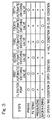
- Table 3 below illustrates the numbers of particles of different sizes (underwater particle number) contained in 1 milliliter of each of the raw water and the filtrate water and the rate of removal of those particles, which are exhibited by each of the depth filters of 1 ⁇ m and 25 ⁇ m in pore size.
- the denominator represents the underwater particle number in the raw water
- the numerator represents the underwater particle number in the filtrate water
- the numerals in the parentheses represent the removal rate.
- the depth filter of 25 ⁇ m in pore size exhibited removal of 95% or more of the particles of 25 or more ⁇ m in particle size, about 88% of the particles of 10 or more ⁇ m in particle size, and 60% or more of the particles of 1 or more ⁇ m in particle size. Considering that most of the particles of 25 or more ⁇ m in particle size have been removed, no suspended particle was noticeable in the filtrate water. Also, the depth filter of 1 ⁇ m in pore size exhibited removal of 99% or more of the particles of 25 or more ⁇ m in particle size, about 94% of the particles of 10 or more ⁇ m in particle size, and 80% or more of the particles of 1 or more ⁇ m in particle size.
- the depth filter 10 employed in the embodiment since the depth filter 10 employed in the embodiment exhibits almost no pressure loss even in the case of the pore size of 1 ⁇ m, the depth filter 10 may have a small projected area and is hence effective to suppress an increase in size of the primary filtration unit 4. Also, as can readily be understood from the result of verification 2 above, the use of the backwashing allows the depth filter to be repeatedly useable. Accordingly, the lifetime can be increased considerably. Yet, as can readily be understood from the result of verification 3 above, the depth filters of 25 ⁇ m in pore size is effective to remove 90% or more of the particles of 25 ⁇ m or more in particle size or 80% or more of the particles of 10 ⁇ m or more in particle size. Accordingly, the pore size of the depth filter 10 may be chosen to be within the range of 1 to 25 ⁇ m.
Landscapes
- Engineering & Computer Science (AREA)
- Water Supply & Treatment (AREA)
- Chemical & Material Sciences (AREA)
- Chemical Kinetics & Catalysis (AREA)
- Nanotechnology (AREA)
- Hydrology & Water Resources (AREA)
- Life Sciences & Earth Sciences (AREA)
- Environmental & Geological Engineering (AREA)
- Organic Chemistry (AREA)
- Mechanical Engineering (AREA)
- Ocean & Marine Engineering (AREA)
- Combustion & Propulsion (AREA)
- Separation Using Semi-Permeable Membranes (AREA)
- Filtration Of Liquid (AREA)
Claims (5)
- Dispositif de filtration comprenant une unité de filtration principale (4) destinée à filtrer de l'eau brute, ladite unité (4) comprenant un milieu filtrant (10) et un carter (9) pour contenir le milieu filtrant (10) :où dans le carter (9) sont définis une ouverture d'alimentation (18) en eau brute pour conduire l'eau brute vers le milieu filtrant (10), une ouverture d'évacuation (16) d'eau filtrée, une ouverture d'alimentation (24) en fluide pour conduire un fluide de rinçage à contre-courant vers le milieu filtrant (10) et un ouverture de purge (22) pour évacuer le fluide utilisé pour rincer à contre-courant le milieu filtrant (10) et l'eau brute ;où le milieu filtrant comprend un filtre en profondeur (10) cylindrique creux de type à pression externe avec une extrémité fermée (10b) et une extrémité ouverte (10a) vers l'ouverture d'évacuation (16) d'eau filtrée afin de permettre la communication de l'intérieur (11) du filtre en profondeur (10) avec l'ouverture d'évacuation (16) d'eau filtrée, le filtre en profondeur (10) étant constitué d'un treillis de fibres synthétiques, d'un textile non tissé, de papier ou de voile textile soudé et/ou moulé et présentant une grandeur de pore comprise entre 1 et 25 µm ; etcaractérisé en ce que ledit dispositif de filtration comprend en outre un chemin d'eau filtrée (8) en communication fluidique avec l'ouverture d'évacuation (16) d'eau filtrée, un chemin de purge (14) en communication fluidique avec l'ouverture de purge (22), un chemin de communication (15) faisant communiquer le chemin d'eau filtrée (8) avec le chemin de purge (14), une deuxième vanne d'inversion (MV2) pour l'ouverture ou la fermeture sélectives du chemin d'eau filtrée (8) en aval du raccord avec le chemin de communication (15), une quatrième vanne d'inversion (MV4) pour l'ouverture ou la fermeture sélectives du chemin de purge (14) entre l'unité de filtration principale (4) et le chemin de communication (15), et une cinquième vanne d'inversion (MV5) pour l'ouverture ou la fermeture sélectives du chemin de communication (15).
- Dispositif de filtration selon la revendication 1, comprenant en outre une unité de filtration secondaire (26) pour une nouvelle filtration de l'eau filtrée par l'unité de filtration principale (4) au moyen d'un milieu filtrant (10) comprenant une membrane d'ultrafiltration ou une membrane d'osmose inverse.
- Dispositif de filtration selon la revendication 1, où l'ouverture d'alimentation (24) en fluide est l'ouverture d'évacuation (16) d'eau filtrée.
- Dispositif de filtration selon la revendication 1, où l'ouverture de purge (22) est l'ouverture d'alimentation (18) en eau brute.
- Procédé de production d'eau filtrée au moyen du dispositif de filtration selon l'une des revendications 1 à 4, ledit procédé comprenant :une étape d'amorçage par évacuation du fluide avec l'eau brute par l'unité de filtration, puis par le chemin de communication (1S) et finalement par le chemin de purge (14) dans un état où la vanne d'inversion (MVS) est ouverte, l'alimentation en eau filtrée (FW) par le milieu filtrant (10) et l'alimentation en fluide pour rinçage à contre-courant vers le milieu filtrant (10) étant interrompues ;une étape de filtration par alimentation en eau brute de l'unité de filtration principale (4) pour provoquer le refoulement de l'eau filtrée vers l'ouverture d'évacuation (16) d'eau filtrée dans un état où l'évacuation de l'eau brute depuis le milieu filtrant (10) et l'alimentation en fluide pour rinçage à contre-courant vers le milieu filtrant (10) sont interrompues ;une étape de rinçage à contre-courant par alimentation en fluide pour rinçage à contre-courant depuis un côté d'eau filtrée vers le milieu filtrant (10), puis évacuation du fluide depuis l'ouverture de purge (22) par le chemin de purge (14), dans un état où l'alimentation en eau filtrée est interrompue.
Applications Claiming Priority (3)
| Application Number | Priority Date | Filing Date | Title |
|---|---|---|---|
| JP2009032872 | 2009-02-16 | ||
| JP2009260648A JP2010207800A (ja) | 2009-02-16 | 2009-11-16 | ろ過ユニットおよびこれを備えたろ過装置 |
| PCT/JP2010/052105 WO2010093026A1 (fr) | 2009-02-16 | 2010-02-12 | Dispositif de filtration et son procédé de fabrication |
Publications (3)
| Publication Number | Publication Date |
|---|---|
| EP2397209A1 EP2397209A1 (fr) | 2011-12-21 |
| EP2397209A4 EP2397209A4 (fr) | 2013-10-30 |
| EP2397209B1 true EP2397209B1 (fr) | 2016-04-20 |
Family
ID=42561866
Family Applications (1)
| Application Number | Title | Priority Date | Filing Date |
|---|---|---|---|
| EP10741303.1A Not-in-force EP2397209B1 (fr) | 2009-02-16 | 2010-02-12 | Dispositif de filtration et son procédé d'operation |
Country Status (7)
| Country | Link |
|---|---|
| US (1) | US9050563B2 (fr) |
| EP (1) | EP2397209B1 (fr) |
| JP (1) | JP2010207800A (fr) |
| KR (1) | KR101717307B1 (fr) |
| CN (1) | CN102316953A (fr) |
| TW (1) | TWI386249B (fr) |
| WO (1) | WO2010093026A1 (fr) |
Families Citing this family (17)
| Publication number | Priority date | Publication date | Assignee | Title |
|---|---|---|---|---|
| JP2010207800A (ja) * | 2009-02-16 | 2010-09-24 | Kuraray Co Ltd | ろ過ユニットおよびこれを備えたろ過装置 |
| AU2012309380B2 (en) * | 2011-09-15 | 2016-10-20 | Toray Industries, Inc. | Freshwater production apparatus and method for producing freshwater |
| EP3335778A1 (fr) | 2012-01-04 | 2018-06-20 | North Carolina State University | Filtre d'eau de disque rotatif |
| CN102949935A (zh) * | 2012-07-12 | 2013-03-06 | 刘爱东 | 水质分流制纯水机 |
| CN104743693A (zh) * | 2013-12-27 | 2015-07-01 | 三菱丽阳株式会社 | 净水系统 |
| JP6333097B2 (ja) * | 2014-07-14 | 2018-05-30 | 東京都下水道サービス株式会社 | 流路洗浄装置を備えたフィルタ洗浄設備 |
| JP6652958B2 (ja) | 2015-03-04 | 2020-02-26 | 株式会社クラレ | バラスト水の製造方法及びバラスト水処理システム |
| CN105536341B (zh) * | 2015-11-17 | 2017-10-13 | 内蒙古包钢钢联股份有限公司 | 反渗透水处理系统一次过滤器和二次过滤器反洗方法 |
| US11767501B2 (en) | 2016-05-09 | 2023-09-26 | Global Algae Technology, LLC | Biological and algae harvesting and cultivation systems and methods |
| US10351815B2 (en) | 2016-05-09 | 2019-07-16 | Global Algae Technologies, Llc | Biological and algae harvesting and cultivation systems and methods |
| US11141701B2 (en) | 2016-08-05 | 2021-10-12 | Toray Industries, Inc. | Computer-readable recording medium on which clogging location specification program for separation membrane module is recorded, water production system, and water production method |
| JP2018065539A (ja) * | 2016-10-21 | 2018-04-26 | 三浦工業株式会社 | バラスト水処理装置 |
| JP2019098271A (ja) * | 2017-12-05 | 2019-06-24 | オルガノ株式会社 | クランプバンド、フィルタハウジングおよび濾過システム |
| CN110665289A (zh) * | 2019-11-19 | 2020-01-10 | 天津市科信塑胶制品股份有限公司 | 一种饮水灌装线过滤装置 |
| US11261102B2 (en) * | 2020-05-01 | 2022-03-01 | Jacob H. Berg | Reverse osmosis prefilter system |
| CN113230724A (zh) * | 2021-06-22 | 2021-08-10 | 中联西北工程设计研究院有限公司 | 一种给排水用过滤系统 |
| KR20250017597A (ko) * | 2023-07-27 | 2025-02-04 | 삼성전자주식회사 | 정수기 |
Family Cites Families (52)
| Publication number | Priority date | Publication date | Assignee | Title |
|---|---|---|---|---|
| JPS6024313A (ja) | 1983-07-19 | 1985-02-07 | Ishikawajima Harima Heavy Ind Co Ltd | 溶鋼の精錬装置 |
| JPS60124617A (ja) | 1983-12-12 | 1985-07-03 | Toshiba Corp | 樹脂封止型発光装置 |
| JPH0261407U (fr) | 1988-10-24 | 1990-05-08 | ||
| JPH0330806A (ja) | 1989-06-27 | 1991-02-08 | Nippon Paul Kk | カートリッジ式フィルタによる活性炭濾過方法 |
| JPH04305209A (ja) | 1991-03-29 | 1992-10-28 | Ishigaki Mech Ind Co | ろ過濃縮装置 |
| US5259954A (en) * | 1991-12-16 | 1993-11-09 | Sepratech, Inc. | Portable intravenous solution preparation apparatus and method |
| JPH06142417A (ja) | 1992-11-06 | 1994-05-24 | Roki Techno:Kk | プリーツ式フイルターカートリッジ |
| US5476591A (en) | 1993-05-25 | 1995-12-19 | Harrison Western Environmental Services, Inc. | Liquid treatment system and method for operating the same |
| JPH07222988A (ja) * | 1994-02-15 | 1995-08-22 | Shikoku Chem Corp | 汚水の処理方法 |
| DE820344T1 (de) * | 1995-04-14 | 1998-05-28 | Aquasource, Rueil-Malmaison | Verfahren zum betrieben und steuern einer gruppe von filtrationsmembranemodulen und eine gruppe von modulen zur ausfürung dieses verfahrens |
| WO1997010047A1 (fr) * | 1995-09-14 | 1997-03-20 | Pall Corporation | Procede et dispositif pour enlever du fer de liquides aqueux |
| JP2779146B2 (ja) | 1995-09-28 | 1998-07-23 | 壽工業株式会社 | 非常用浄水装置 |
| JP2000117013A (ja) | 1998-10-14 | 2000-04-25 | Marusei Heavy Industry Works Ltd | 海水等を濾過する超微細型フィルタ− |
| CN2431033Y (zh) * | 1998-10-18 | 2001-05-23 | 杜焕强 | 供水过滤净水器 |
| CA2367571A1 (fr) * | 1999-03-17 | 2000-09-21 | Foster-Miller, Inc. | Gels sensibles et leurs procedes d'utilisation |
| JP4053200B2 (ja) | 1999-12-20 | 2008-02-27 | 神奈川機器工業株式会社 | 逆洗型ろ過機 |
| JP2002096064A (ja) | 2000-09-22 | 2002-04-02 | Kuraray Co Ltd | 貯水の循環浄化方法 |
| NL1017681C2 (nl) | 2001-03-23 | 2002-10-10 | Prime Water Systems Gmbh | Filtersysteem. |
| JP2002355678A (ja) | 2001-05-30 | 2002-12-10 | Mishima Kosan Co Ltd | 殺菌水の製造方法及び製造装置 |
| CN1543440A (zh) * | 2001-06-19 | 2004-11-03 | ��������ҽѧ����˾ | 医用级水生产系统 |
| DE10155591B4 (de) | 2001-11-13 | 2004-05-06 | Seitzschenk Filtersystems Gmbh | Filtermodul und Verfahren zu dessen Herstellung |
| JP3857164B2 (ja) | 2002-03-22 | 2006-12-13 | 日本碍子株式会社 | フィルタの設置構造 |
| ATE360683T1 (de) * | 2002-05-14 | 2007-05-15 | Merck & Co Inc | Verfahren zur reinigung von adenovirus |
| US20040118780A1 (en) | 2002-12-20 | 2004-06-24 | Barnstead/Thermolyne Corporation | Water purification system and method |
| US7270745B2 (en) * | 2003-08-04 | 2007-09-18 | Schwartzkopf Steven H | Liquid filtration apparatus embodying super-buoyant filtration particles |
| ES2329607T3 (es) * | 2004-02-23 | 2009-11-27 | Crucell Holland B.V. | Metodos de purificacion de virus. |
| JP2006082031A (ja) | 2004-09-17 | 2006-03-30 | Tokyo Metropolis | Y形ストレーナ |
| PL1805211T3 (pl) * | 2004-10-27 | 2009-09-30 | Xellia Pharmaceuticals Aps | Oczyszczanie glikopeptydów |
| JP4723229B2 (ja) | 2004-11-24 | 2011-07-13 | 武郎 吉田 | 濾過器 |
| DE202005005118U1 (de) * | 2005-03-29 | 2005-06-16 | Bobak Wassertechnik Gmbh | Festbettfilteranlage |
| WO2006108025A2 (fr) * | 2005-04-05 | 2006-10-12 | Cargill, Incorporated | Systeme et procede d'elimination des contaminants presents dans les eaux residuaires |
| JP4821361B2 (ja) | 2006-02-20 | 2011-11-24 | Jfeエンジニアリング株式会社 | バラスト水処理方法 |
| KR100963351B1 (ko) | 2005-06-10 | 2010-06-14 | 제이에프이 엔지니어링 가부시키가이샤 | 밸러스트수 처리 장치 및 처리 방법 |
| JP5203563B2 (ja) | 2005-11-08 | 2013-06-05 | 株式会社東芝 | 膜ろ過システム |
| JP2007160242A (ja) * | 2005-12-15 | 2007-06-28 | Japan Organo Co Ltd | バラスト水製造装置、これを搭載する船舶及びバラスト水の製造方法 |
| KR101323765B1 (ko) * | 2006-02-24 | 2013-10-31 | 가부시키가이샤 아이에이치아이 카이덴기카이 | 실리콘입자의 처리방법 및 장치 |
| JP2007284531A (ja) | 2006-04-14 | 2007-11-01 | Mitsubishi Chemicals Corp | ポリ塩化ビニル樹脂溶解液からの不溶物の除去方法 |
| WO2007130029A1 (fr) | 2006-05-02 | 2007-11-15 | Birgir Nilsen | Appareil et procede permettant de separer et de filtrer des particules et des organismes a partir de l'ecoulement d'un grand volume de liquide |
| JP2007325994A (ja) | 2006-06-06 | 2007-12-20 | Kurita Water Ind Ltd | 濾過装置 |
| JP4706564B2 (ja) | 2006-06-06 | 2011-06-22 | 東レ株式会社 | 浄水器 |
| WO2007142068A1 (fr) | 2006-06-07 | 2007-12-13 | Kabushiki Kaisha Yaskawa Denki | Appareil de purification d'eau de ballast de navire |
| JP2007326065A (ja) * | 2006-06-09 | 2007-12-20 | Toray Ind Inc | 浄水器 |
| WO2008038575A1 (fr) | 2006-09-25 | 2008-04-03 | Toray Industries, Inc. | PROCÉDÉ DE FONCTIONNEMENT D'Une installation DE FILTRATION suR MEMBRANE D'OSMOSE INVERSE, ET installation DE FILTRATION sur MEMBRANE D'OSMOSE INVERSE |
| JP2008136886A (ja) | 2006-11-29 | 2008-06-19 | Mitsui Eng & Shipbuild Co Ltd | 濾過装置の逆洗方法 |
| JP4866221B2 (ja) | 2006-12-07 | 2012-02-01 | オルガノ株式会社 | ろ過処理装置およびろ過処理方法 |
| US20080257824A1 (en) | 2007-04-23 | 2008-10-23 | Square Peg Engineering, Llc | Method and Apparatus for Water Purification and Regeneration of Micro-filtration Tubules |
| JP2009032872A (ja) | 2007-07-26 | 2009-02-12 | Sharp Corp | 半導体装置の製造方法 |
| JP5071861B2 (ja) | 2008-04-16 | 2012-11-14 | コニカミノルタビジネステクノロジーズ株式会社 | 画像読取り装置 |
| JP4877281B2 (ja) | 2008-06-11 | 2012-02-15 | Jfeエンジニアリング株式会社 | バラスト水処理装置およびバラスト水処理方法 |
| TWM345640U (en) | 2008-07-15 | 2008-12-01 | Shu-Heng Su | Enclosure structure of seawater filtering device for vessels |
| SI2184095T1 (sl) * | 2008-11-11 | 2012-05-31 | Emd Millipore Corp | Sistem in postopek za filtracijo tekočin |
| JP2010207800A (ja) * | 2009-02-16 | 2010-09-24 | Kuraray Co Ltd | ろ過ユニットおよびこれを備えたろ過装置 |
-
2009
- 2009-11-16 JP JP2009260648A patent/JP2010207800A/ja active Pending
-
2010
- 2010-02-12 WO PCT/JP2010/052105 patent/WO2010093026A1/fr not_active Ceased
- 2010-02-12 CN CN2010800079028A patent/CN102316953A/zh active Pending
- 2010-02-12 KR KR1020117019035A patent/KR101717307B1/ko not_active Expired - Fee Related
- 2010-02-12 US US13/148,959 patent/US9050563B2/en not_active Expired - Fee Related
- 2010-02-12 EP EP10741303.1A patent/EP2397209B1/fr not_active Not-in-force
- 2010-02-22 TW TW099104983A patent/TWI386249B/zh not_active IP Right Cessation
Non-Patent Citations (1)
| Title |
|---|
| None * |
Also Published As
| Publication number | Publication date |
|---|---|
| TW201039902A (en) | 2010-11-16 |
| EP2397209A1 (fr) | 2011-12-21 |
| JP2010207800A (ja) | 2010-09-24 |
| CN102316953A (zh) | 2012-01-11 |
| KR20110126624A (ko) | 2011-11-23 |
| KR101717307B1 (ko) | 2017-03-16 |
| EP2397209A4 (fr) | 2013-10-30 |
| US20110309038A1 (en) | 2011-12-22 |
| WO2010093026A1 (fr) | 2010-08-19 |
| TWI386249B (zh) | 2013-02-21 |
| US9050563B2 (en) | 2015-06-09 |
Similar Documents
| Publication | Publication Date | Title |
|---|---|---|
| US9050563B2 (en) | Filtering device and method of manufacturing same | |
| JP5723088B2 (ja) | バラスト水製造装置 | |
| KR101954760B1 (ko) | 역플러싱 전처리 필터를 구비한 정수시스템 및 그 정수방법 | |
| WO2014103854A1 (fr) | Dispositif de traitement d'eau de ballast et procédé de refoulement destiné à un dispositif de traitement d'eau de ballast | |
| EP4154960A1 (fr) | Ensemble filtre hybride | |
| WO2007105851A1 (fr) | Appareil de traitement de l'eau utilisant un module membranaire submergé à l'intérieur d'un filtre à fibres | |
| KR100679231B1 (ko) | 3 fm 정밀여과장치 | |
| KR101446273B1 (ko) | 수두차를 이용한 상향류 모래 여과장치의 운영 방법 및 이를 이용한 수처리 방법 | |
| KR20170119706A (ko) | 밸러스트수의 제조 방법 및 밸러스트수 처리 시스템 | |
| US6896818B2 (en) | Water filtration and recycling for stone fabrication equipment | |
| KR101350537B1 (ko) | 멀티 화이버층을 이용한 여과장치 및 그 역세방법 | |
| CN107376647B (zh) | 一种开式循环水旁滤装置及使用其的循环水处理方法 | |
| JP2012176343A (ja) | 膜濾過装置 | |
| KR102069531B1 (ko) | 역세형 다층여과 필터 및 이를 이용한 여과방법 | |
| JP5105036B2 (ja) | 二元給配水システム | |
| JP5905905B2 (ja) | デプスフィルタを用いた濾過ユニット、及びデプスフィルタを用いた濾過装置 | |
| KR100733691B1 (ko) | 여과장치 | |
| RU2400285C2 (ru) | Устройство для фильтрования жидкостей | |
| KR20180037393A (ko) | 섬유여과장치 | |
| JP2009024111A (ja) | 選炭システム | |
| CN207361912U (zh) | 一种精蒽咔唑生产线的污水深度净化系统 | |
| JP6060036B2 (ja) | 膜ろ過システムの洗浄方法 | |
| EP4548993A1 (fr) | Ensemble de nettoyage chimique et de filtre hybride | |
| KR102459933B1 (ko) | 상수도관 유지관리 여과시스템 | |
| JP5968592B2 (ja) | 浄水システムおよびその運転方法 |
Legal Events
| Date | Code | Title | Description |
|---|---|---|---|
| PUAI | Public reference made under article 153(3) epc to a published international application that has entered the european phase |
Free format text: ORIGINAL CODE: 0009012 |
|
| 17P | Request for examination filed |
Effective date: 20110907 |
|
| AK | Designated contracting states |
Kind code of ref document: A1 Designated state(s): AT BE BG CH CY CZ DE DK EE ES FI FR GB GR HR HU IE IS IT LI LT LU LV MC MK MT NL NO PL PT RO SE SI SK SM TR |
|
| DAX | Request for extension of the european patent (deleted) | ||
| A4 | Supplementary search report drawn up and despatched |
Effective date: 20130930 |
|
| RIC1 | Information provided on ipc code assigned before grant |
Ipc: B63B 13/00 20060101ALI20130924BHEP Ipc: B01D 61/04 20060101ALI20130924BHEP Ipc: C02F 1/00 20060101ALI20130924BHEP Ipc: B01D 29/66 20060101ALI20130924BHEP Ipc: B01D 24/46 20060101ALI20130924BHEP Ipc: B01D 29/11 20060101AFI20130924BHEP Ipc: B01D 61/16 20060101ALI20130924BHEP |
|
| 17Q | First examination report despatched |
Effective date: 20140611 |
|
| REG | Reference to a national code |
Ref country code: DE Ref legal event code: R079 Ref document number: 602010032505 Country of ref document: DE Free format text: PREVIOUS MAIN CLASS: B01D0029110000 Ipc: B01D0061040000 |
|
| GRAP | Despatch of communication of intention to grant a patent |
Free format text: ORIGINAL CODE: EPIDOSNIGR1 |
|
| RIC1 | Information provided on ipc code assigned before grant |
Ipc: B01D 24/46 20060101ALI20150902BHEP Ipc: B01D 61/16 20060101ALI20150902BHEP Ipc: C02F 1/00 20060101ALI20150902BHEP Ipc: B01D 61/04 20060101AFI20150902BHEP |
|
| INTG | Intention to grant announced |
Effective date: 20151001 |
|
| GRAS | Grant fee paid |
Free format text: ORIGINAL CODE: EPIDOSNIGR3 |
|
| GRAJ | Information related to disapproval of communication of intention to grant by the applicant or resumption of examination proceedings by the epo deleted |
Free format text: ORIGINAL CODE: EPIDOSDIGR1 |
|
| GRAR | Information related to intention to grant a patent recorded |
Free format text: ORIGINAL CODE: EPIDOSNIGR71 |
|
| GRAA | (expected) grant |
Free format text: ORIGINAL CODE: 0009210 |
|
| INTG | Intention to grant announced |
Effective date: 20160223 |
|
| AK | Designated contracting states |
Kind code of ref document: B1 Designated state(s): AT BE BG CH CY CZ DE DK EE ES FI FR GB GR HR HU IE IS IT LI LT LU LV MC MK MT NL NO PL PT RO SE SI SK SM TR |
|
| REG | Reference to a national code |
Ref country code: GB Ref legal event code: FG4D |
|
| REG | Reference to a national code |
Ref country code: CH Ref legal event code: EP |
|
| REG | Reference to a national code |
Ref country code: AT Ref legal event code: REF Ref document number: 791789 Country of ref document: AT Kind code of ref document: T Effective date: 20160515 |
|
| REG | Reference to a national code |
Ref country code: IE Ref legal event code: FG4D |
|
| REG | Reference to a national code |
Ref country code: DE Ref legal event code: R096 Ref document number: 602010032505 Country of ref document: DE |
|
| REG | Reference to a national code |
Ref country code: LT Ref legal event code: MG4D |
|
| REG | Reference to a national code |
Ref country code: AT Ref legal event code: MK05 Ref document number: 791789 Country of ref document: AT Kind code of ref document: T Effective date: 20160420 |
|
| REG | Reference to a national code |
Ref country code: NL Ref legal event code: MP Effective date: 20160420 |
|
| PG25 | Lapsed in a contracting state [announced via postgrant information from national office to epo] |
Ref country code: PL Free format text: LAPSE BECAUSE OF FAILURE TO SUBMIT A TRANSLATION OF THE DESCRIPTION OR TO PAY THE FEE WITHIN THE PRESCRIBED TIME-LIMIT Effective date: 20160420 Ref country code: NL Free format text: LAPSE BECAUSE OF FAILURE TO SUBMIT A TRANSLATION OF THE DESCRIPTION OR TO PAY THE FEE WITHIN THE PRESCRIBED TIME-LIMIT Effective date: 20160420 Ref country code: NO Free format text: LAPSE BECAUSE OF FAILURE TO SUBMIT A TRANSLATION OF THE DESCRIPTION OR TO PAY THE FEE WITHIN THE PRESCRIBED TIME-LIMIT Effective date: 20160720 Ref country code: FI Free format text: LAPSE BECAUSE OF FAILURE TO SUBMIT A TRANSLATION OF THE DESCRIPTION OR TO PAY THE FEE WITHIN THE PRESCRIBED TIME-LIMIT Effective date: 20160420 Ref country code: LT Free format text: LAPSE BECAUSE OF FAILURE TO SUBMIT A TRANSLATION OF THE DESCRIPTION OR TO PAY THE FEE WITHIN THE PRESCRIBED TIME-LIMIT Effective date: 20160420 |
|
| PG25 | Lapsed in a contracting state [announced via postgrant information from national office to epo] |
Ref country code: PT Free format text: LAPSE BECAUSE OF FAILURE TO SUBMIT A TRANSLATION OF THE DESCRIPTION OR TO PAY THE FEE WITHIN THE PRESCRIBED TIME-LIMIT Effective date: 20160822 Ref country code: HR Free format text: LAPSE BECAUSE OF FAILURE TO SUBMIT A TRANSLATION OF THE DESCRIPTION OR TO PAY THE FEE WITHIN THE PRESCRIBED TIME-LIMIT Effective date: 20160420 Ref country code: SE Free format text: LAPSE BECAUSE OF FAILURE TO SUBMIT A TRANSLATION OF THE DESCRIPTION OR TO PAY THE FEE WITHIN THE PRESCRIBED TIME-LIMIT Effective date: 20160420 Ref country code: GR Free format text: LAPSE BECAUSE OF FAILURE TO SUBMIT A TRANSLATION OF THE DESCRIPTION OR TO PAY THE FEE WITHIN THE PRESCRIBED TIME-LIMIT Effective date: 20160721 Ref country code: AT Free format text: LAPSE BECAUSE OF FAILURE TO SUBMIT A TRANSLATION OF THE DESCRIPTION OR TO PAY THE FEE WITHIN THE PRESCRIBED TIME-LIMIT Effective date: 20160420 Ref country code: LV Free format text: LAPSE BECAUSE OF FAILURE TO SUBMIT A TRANSLATION OF THE DESCRIPTION OR TO PAY THE FEE WITHIN THE PRESCRIBED TIME-LIMIT Effective date: 20160420 Ref country code: ES Free format text: LAPSE BECAUSE OF FAILURE TO SUBMIT A TRANSLATION OF THE DESCRIPTION OR TO PAY THE FEE WITHIN THE PRESCRIBED TIME-LIMIT Effective date: 20160420 |
|
| PG25 | Lapsed in a contracting state [announced via postgrant information from national office to epo] |
Ref country code: BE Free format text: LAPSE BECAUSE OF FAILURE TO SUBMIT A TRANSLATION OF THE DESCRIPTION OR TO PAY THE FEE WITHIN THE PRESCRIBED TIME-LIMIT Effective date: 20160420 Ref country code: IT Free format text: LAPSE BECAUSE OF FAILURE TO SUBMIT A TRANSLATION OF THE DESCRIPTION OR TO PAY THE FEE WITHIN THE PRESCRIBED TIME-LIMIT Effective date: 20160420 |
|
| REG | Reference to a national code |
Ref country code: DE Ref legal event code: R097 Ref document number: 602010032505 Country of ref document: DE |
|
| PG25 | Lapsed in a contracting state [announced via postgrant information from national office to epo] |
Ref country code: SK Free format text: LAPSE BECAUSE OF FAILURE TO SUBMIT A TRANSLATION OF THE DESCRIPTION OR TO PAY THE FEE WITHIN THE PRESCRIBED TIME-LIMIT Effective date: 20160420 Ref country code: RO Free format text: LAPSE BECAUSE OF FAILURE TO SUBMIT A TRANSLATION OF THE DESCRIPTION OR TO PAY THE FEE WITHIN THE PRESCRIBED TIME-LIMIT Effective date: 20160420 Ref country code: EE Free format text: LAPSE BECAUSE OF FAILURE TO SUBMIT A TRANSLATION OF THE DESCRIPTION OR TO PAY THE FEE WITHIN THE PRESCRIBED TIME-LIMIT Effective date: 20160420 Ref country code: CZ Free format text: LAPSE BECAUSE OF FAILURE TO SUBMIT A TRANSLATION OF THE DESCRIPTION OR TO PAY THE FEE WITHIN THE PRESCRIBED TIME-LIMIT Effective date: 20160420 Ref country code: DK Free format text: LAPSE BECAUSE OF FAILURE TO SUBMIT A TRANSLATION OF THE DESCRIPTION OR TO PAY THE FEE WITHIN THE PRESCRIBED TIME-LIMIT Effective date: 20160420 |
|
| PLBE | No opposition filed within time limit |
Free format text: ORIGINAL CODE: 0009261 |
|
| STAA | Information on the status of an ep patent application or granted ep patent |
Free format text: STATUS: NO OPPOSITION FILED WITHIN TIME LIMIT |
|
| PG25 | Lapsed in a contracting state [announced via postgrant information from national office to epo] |
Ref country code: SM Free format text: LAPSE BECAUSE OF FAILURE TO SUBMIT A TRANSLATION OF THE DESCRIPTION OR TO PAY THE FEE WITHIN THE PRESCRIBED TIME-LIMIT Effective date: 20160420 |
|
| 26N | No opposition filed |
Effective date: 20170123 |
|
| PG25 | Lapsed in a contracting state [announced via postgrant information from national office to epo] |
Ref country code: SI Free format text: LAPSE BECAUSE OF FAILURE TO SUBMIT A TRANSLATION OF THE DESCRIPTION OR TO PAY THE FEE WITHIN THE PRESCRIBED TIME-LIMIT Effective date: 20160420 |
|
| PG25 | Lapsed in a contracting state [announced via postgrant information from national office to epo] |
Ref country code: MC Free format text: LAPSE BECAUSE OF FAILURE TO SUBMIT A TRANSLATION OF THE DESCRIPTION OR TO PAY THE FEE WITHIN THE PRESCRIBED TIME-LIMIT Effective date: 20160420 |
|
| REG | Reference to a national code |
Ref country code: CH Ref legal event code: PL |
|
| PG25 | Lapsed in a contracting state [announced via postgrant information from national office to epo] |
Ref country code: LI Free format text: LAPSE BECAUSE OF NON-PAYMENT OF DUE FEES Effective date: 20170228 Ref country code: CH Free format text: LAPSE BECAUSE OF NON-PAYMENT OF DUE FEES Effective date: 20170228 |
|
| REG | Reference to a national code |
Ref country code: IE Ref legal event code: MM4A |
|
| REG | Reference to a national code |
Ref country code: FR Ref legal event code: ST Effective date: 20171031 |
|
| PG25 | Lapsed in a contracting state [announced via postgrant information from national office to epo] |
Ref country code: LU Free format text: LAPSE BECAUSE OF NON-PAYMENT OF DUE FEES Effective date: 20170212 |
|
| PG25 | Lapsed in a contracting state [announced via postgrant information from national office to epo] |
Ref country code: FR Free format text: LAPSE BECAUSE OF NON-PAYMENT OF DUE FEES Effective date: 20170228 |
|
| PG25 | Lapsed in a contracting state [announced via postgrant information from national office to epo] |
Ref country code: IE Free format text: LAPSE BECAUSE OF NON-PAYMENT OF DUE FEES Effective date: 20170212 |
|
| PG25 | Lapsed in a contracting state [announced via postgrant information from national office to epo] |
Ref country code: MT Free format text: LAPSE BECAUSE OF NON-PAYMENT OF DUE FEES Effective date: 20170212 |
|
| PG25 | Lapsed in a contracting state [announced via postgrant information from national office to epo] |
Ref country code: HU Free format text: LAPSE BECAUSE OF FAILURE TO SUBMIT A TRANSLATION OF THE DESCRIPTION OR TO PAY THE FEE WITHIN THE PRESCRIBED TIME-LIMIT; INVALID AB INITIO Effective date: 20100212 |
|
| PG25 | Lapsed in a contracting state [announced via postgrant information from national office to epo] |
Ref country code: BG Free format text: LAPSE BECAUSE OF FAILURE TO SUBMIT A TRANSLATION OF THE DESCRIPTION OR TO PAY THE FEE WITHIN THE PRESCRIBED TIME-LIMIT Effective date: 20160420 |
|
| PG25 | Lapsed in a contracting state [announced via postgrant information from national office to epo] |
Ref country code: CY Free format text: LAPSE BECAUSE OF NON-PAYMENT OF DUE FEES Effective date: 20160420 |
|
| PG25 | Lapsed in a contracting state [announced via postgrant information from national office to epo] |
Ref country code: MK Free format text: LAPSE BECAUSE OF FAILURE TO SUBMIT A TRANSLATION OF THE DESCRIPTION OR TO PAY THE FEE WITHIN THE PRESCRIBED TIME-LIMIT Effective date: 20160420 |
|
| PG25 | Lapsed in a contracting state [announced via postgrant information from national office to epo] |
Ref country code: TR Free format text: LAPSE BECAUSE OF FAILURE TO SUBMIT A TRANSLATION OF THE DESCRIPTION OR TO PAY THE FEE WITHIN THE PRESCRIBED TIME-LIMIT Effective date: 20160420 |
|
| PGFP | Annual fee paid to national office [announced via postgrant information from national office to epo] |
Ref country code: DE Payment date: 20200129 Year of fee payment: 11 Ref country code: GB Payment date: 20200206 Year of fee payment: 11 |
|
| PG25 | Lapsed in a contracting state [announced via postgrant information from national office to epo] |
Ref country code: IS Free format text: LAPSE BECAUSE OF FAILURE TO SUBMIT A TRANSLATION OF THE DESCRIPTION OR TO PAY THE FEE WITHIN THE PRESCRIBED TIME-LIMIT Effective date: 20160820 |
|
| REG | Reference to a national code |
Ref country code: DE Ref legal event code: R119 Ref document number: 602010032505 Country of ref document: DE |
|
| GBPC | Gb: european patent ceased through non-payment of renewal fee |
Effective date: 20210212 |
|
| PG25 | Lapsed in a contracting state [announced via postgrant information from national office to epo] |
Ref country code: DE Free format text: LAPSE BECAUSE OF NON-PAYMENT OF DUE FEES Effective date: 20210901 Ref country code: GB Free format text: LAPSE BECAUSE OF NON-PAYMENT OF DUE FEES Effective date: 20210212 |