EP2397404A2 - Support télescopique - Google Patents
Support télescopique Download PDFInfo
- Publication number
- EP2397404A2 EP2397404A2 EP11169665A EP11169665A EP2397404A2 EP 2397404 A2 EP2397404 A2 EP 2397404A2 EP 11169665 A EP11169665 A EP 11169665A EP 11169665 A EP11169665 A EP 11169665A EP 2397404 A2 EP2397404 A2 EP 2397404A2
- Authority
- EP
- European Patent Office
- Prior art keywords
- strut
- cable
- telescopic
- fixed
- movable
- Prior art date
- Legal status (The legal status is an assumption and is not a legal conclusion. Google has not performed a legal analysis and makes no representation as to the accuracy of the status listed.)
- Withdrawn
Links
- 238000000034 method Methods 0.000 claims abstract description 5
- 239000003989 dielectric material Substances 0.000 claims description 9
- RZVHIXYEVGDQDX-UHFFFAOYSA-N 9,10-anthraquinone Chemical compound C1=CC=C2C(=O)C3=CC=CC=C3C(=O)C2=C1 RZVHIXYEVGDQDX-UHFFFAOYSA-N 0.000 claims description 3
- 230000003287 optical effect Effects 0.000 claims description 3
- 238000005204 segregation Methods 0.000 description 4
- 238000004891 communication Methods 0.000 description 3
- 230000008878 coupling Effects 0.000 description 3
- 238000010168 coupling process Methods 0.000 description 3
- 238000005859 coupling reaction Methods 0.000 description 3
- 238000013016 damping Methods 0.000 description 2
- 239000013536 elastomeric material Substances 0.000 description 2
- 239000011810 insulating material Substances 0.000 description 2
- 239000000463 material Substances 0.000 description 2
- 238000004804 winding Methods 0.000 description 2
- 239000004696 Poly ether ether ketone Substances 0.000 description 1
- 230000009286 beneficial effect Effects 0.000 description 1
- JUPQTSLXMOCDHR-UHFFFAOYSA-N benzene-1,4-diol;bis(4-fluorophenyl)methanone Chemical compound OC1=CC=C(O)C=C1.C1=CC(F)=CC=C1C(=O)C1=CC=C(F)C=C1 JUPQTSLXMOCDHR-UHFFFAOYSA-N 0.000 description 1
- 239000002131 composite material Substances 0.000 description 1
- 230000000694 effects Effects 0.000 description 1
- 230000005489 elastic deformation Effects 0.000 description 1
- 238000005516 engineering process Methods 0.000 description 1
- 239000000835 fiber Substances 0.000 description 1
- 239000012530 fluid Substances 0.000 description 1
- 238000010438 heat treatment Methods 0.000 description 1
- 239000012212 insulator Substances 0.000 description 1
- 230000013011 mating Effects 0.000 description 1
- 238000012986 modification Methods 0.000 description 1
- 230000004048 modification Effects 0.000 description 1
- 239000012811 non-conductive material Substances 0.000 description 1
- 239000004033 plastic Substances 0.000 description 1
- 229920003023 plastic Polymers 0.000 description 1
- 229920002530 polyetherether ketone Polymers 0.000 description 1
- 239000004810 polytetrafluoroethylene Substances 0.000 description 1
- 229920001343 polytetrafluoroethylene Polymers 0.000 description 1
- 230000002028 premature Effects 0.000 description 1
Images

Classifications
-
- B—PERFORMING OPERATIONS; TRANSPORTING
- B64—AIRCRAFT; AVIATION; COSMONAUTICS
- B64C—AEROPLANES; HELICOPTERS
- B64C9/00—Adjustable control surfaces or members, e.g. rudders
- B64C9/14—Adjustable control surfaces or members, e.g. rudders forming slots
-
- B—PERFORMING OPERATIONS; TRANSPORTING
- B64—AIRCRAFT; AVIATION; COSMONAUTICS
- B64C—AEROPLANES; HELICOPTERS
- B64C9/00—Adjustable control surfaces or members, e.g. rudders
- B64C9/14—Adjustable control surfaces or members, e.g. rudders forming slots
- B64C9/22—Adjustable control surfaces or members, e.g. rudders forming slots at the front of the wing
-
- H—ELECTRICITY
- H01—ELECTRIC ELEMENTS
- H01B—CABLES; CONDUCTORS; INSULATORS; SELECTION OF MATERIALS FOR THEIR CONDUCTIVE, INSULATING OR DIELECTRIC PROPERTIES
- H01B7/00—Insulated conductors or cables characterised by their form
- H01B7/06—Extensible conductors or cables, e.g. self-coiling cords
- H01B7/065—Extensible conductors or cables, e.g. self-coiling cords having the shape of an helix
-
- H—ELECTRICITY
- H02—GENERATION; CONVERSION OR DISTRIBUTION OF ELECTRIC POWER
- H02G—INSTALLATION OF ELECTRIC CABLES OR LINES, OR OF COMBINED OPTICAL AND ELECTRIC CABLES OR LINES
- H02G11/00—Arrangements of electric cables or lines between relatively-movable parts
- H02G11/006—Arrangements of electric cables or lines between relatively-movable parts using extensible carrier for the cable, e.g. self-coiling spring
-
- Y—GENERAL TAGGING OF NEW TECHNOLOGICAL DEVELOPMENTS; GENERAL TAGGING OF CROSS-SECTIONAL TECHNOLOGIES SPANNING OVER SEVERAL SECTIONS OF THE IPC; TECHNICAL SUBJECTS COVERED BY FORMER USPC CROSS-REFERENCE ART COLLECTIONS [XRACs] AND DIGESTS
- Y02—TECHNOLOGIES OR APPLICATIONS FOR MITIGATION OR ADAPTATION AGAINST CLIMATE CHANGE
- Y02T—CLIMATE CHANGE MITIGATION TECHNOLOGIES RELATED TO TRANSPORTATION
- Y02T50/00—Aeronautics or air transport
- Y02T50/40—Weight reduction
Definitions
- the present invention relates to a telescopic strut for electrically connecting a fixed structure of an aircraft to a movable structure mounted to the fixed structure.
- Ice protection of aircraft leading edge structures has traditionally been provided on large commercial aircraft through the use of bleed air. Smaller aircraft have used combinations of inflatable rubber de-icing boots, and de-icing fluid. Helicopters have had significant experience of electrical ice protection solutions. Most previous applications of helicopter electrical ice protection have been on fixed structures, which by definition do not move. The only exception to this being electrical ice protection on helicopter rotor blades where the power is transmitted through a slip ring system of joints, the technology of which is used over much of the engineering industry.
- WO2006/027624A describes a coupling arrangement for coupling services between an aircraft wing fixed aerofoil component and a extendable leading edge slat mounted thereto.
- the coupling arrangement includes a housing for connection to the fixed aerofoil structure, and a hollow telescopic assembly extendable between a retracted and an extended position.
- a service carrying conduit arrangement carries the services, such as electrical power cables, between the fixed aerofoil component and the leading edge slat, and extends through the hollow telescopic assembly.
- the service carrying conduit arrangement is flexible and excess thereof is located within the housing when the telescopic assembly is in the retracted position.
- the housing for storing the excess of the flexible conduit carries an undesirable weight and space penalty.
- a first aspect of the invention provides a telescopic strut for electrically connecting a fixed structure of an aircraft to a movable structure mounted to the fixed structure, wherein the strut is adapted to be mechanically connected to the fixed structure by its one end and to be mechanically connected to the movable structure by its opposite end, the strut comprising a plurality of telescopic elements and containing a helically coiled electrical cable, wherein the cable is adapted to move between retracted and extended positions with the telescoping of the strut.
- a further aspect of the invention provides a method of operating an aircraft having a movable structure mounted to a fixed structure, and a telescopic strut mechanically and electrically connected between the fixed and movable structures, wherein the strut comprises a plurality of telescopic elements and contains at least one helically coiled electrical cable, the method comprising moving the movable structure between retracted and extended positions accompanied by corresponding telescoping of the strut and movement of the coiled cable between retracted and extended positions to maintain electrical connection between the fixed and movable structures.
- the invention is advantageous in that when the strut is in its retracted position, excess cabling is stored within the strut and therefore does not require any additional housing for storing the excess cabling. This saves significant space and weight.
- the cable may be pre-sprung so as to be biased to its retracted position. This may be achieved by pre-forming a flexible insulator of the cable to a naturally retracted state, that can extend by elastic deformation. Alternatively, a helical spring may be attached to the cable biased to a retracted position.
- the cable may need to be electrically segregated from strut.
- a dielectric material may therefore be provided between the cable and the strut.
- the dielectric material may maintain a desired clearance between the cable and the strut. For example, if a high tension cable is contained within metallic, conductive telescopic elements the desired clearance may be at least approximately 10 mm.
- the dielectric material may be a flexible liner inside the strut.
- the liner may be convoluted.
- the convoluted liner can concertina like a bellows as the strut moves between its extended and retracted positions.
- the convoluted liner may extend from one end of the strut to the opposite end.
- the cable may be embedded in the liner.
- the liner may be of substantially uniform thickness and formed in several sections, each fixed to the inside of a respective strut element.
- the dielectric material may additionally or alternatively be one or more grommets around the cable.
- the grommets may each have a central hole through which the cable passes.
- the grommets may be positioned at angularly spaced locations along the helically coiled cable.
- the grommets may include additional holes to provide a damping effect to improve vibration protection for the cable.
- the cable may be a power cable and/or a sensor cable.
- One or more cables may be provided in the strut.
- connection terminal may be provided at each end of the strut.
- the connection terminal may be used to connect a mating connection terminal on each of the fixed and movable structures.
- the connection terminals may be electrically connected to each end of the cable.
- an aircraft comprises a fixed structure, a movable structure mounted to the fixed structure, and a telescopic strut in accordance with this invention mechanically connected to the fixed structure by its one end and mechanically connected to the movable structure by its opposite end.
- the fixed structure may be a fixed aerofoil and the movable structure may be a flight control surface.
- the flight control surface may be a wing leading edge slat.
- a wireless or optical sensor line may additionally be provided between the fixed and movable structures.
- the sensor line may form part of a control system for one or more devices mounted in/on the movable structure which are supplied with electrical power by the strut.
- a plurality of the telescopic struts may be provided between the fixed and movable structures.
- one strut may convey a power cable and another a sensor cable.
- several struts, each conveying one or more power and/or sensor cables may be used.
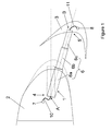
- Figure 1 illustrates a telescopic electrically connecting strut 1 in both its retracted position (shown in broken line) and its extended position (full line).
- the telescopic strut electrically connects between a fixed structure 2 and a movable structure 3 of an aircraft.
- the structure 2 is a fixed main wing structure and the structure 3 is a leading edge slat (or flap).
- the telescopic strut 1 has a first end 4 attached to the fixed structure 2 and a second end 5, opposite the first, attached to the movable structure 3.
- the telescopic strut 1 is pivotally connected to the fixed structure 2 at a pivot point A, and is pivotally connected to the movable structure at pivot point B.
- the telescopic strut 1 comprises several hollow tubular elements 6. In the particular example shown these elements 6 number three and are referenced as 6a, 6b, 6c. Each element 6 fits within one another in a sliding fashion, with the largest element 6a preferably being that attached to the fixed structure 2.
- the movable structure 3 is translated between retracted and extended positions with respect to the fixed structure 2 by further mechanical actuators, not illustrated, in a conventional manner.
- a respective electrical connection terminal 7, 8 At each end 4, 5 of the telescopic strut 1 is a respective electrical connection terminal 7, 8.
- the electrical connection terminal 7 is connected to an electrical path (not shown) within the fixed structure 2, and the electrical connection terminal 8 is connected to an electrical device (not shown) within the movable structure 3.
- the electrical device may be, for example, an electrical heating device for de-icing purposes or one or more items of electronic apparatus.
- the telescopic strut 1 provides the communication of electrical power and/or communication signals between the fixed structure 2 and the movable structure 3, as explained more clearly with reference to Figures 2 and 3 .
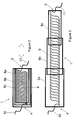
- Figure 2 illustrates the telescopic strut 1 of Figure 1 in greater detail and in cross-section, with the strut 1 in its retracted position.
- the strut 1 includes three cylindrical, hollow tubular telescopic elements 6a, 6b and 6c. These elements 6 are arranged to slidably fit one with the other, i.e. such that the smallest diameter telescopic element 6c is slidably received within telescopic element 6b, which in turn is slidably received within the telescopic element 6a. It will of course be appreciated that more or less telescopic elements 6 may be provided as required and other geometries apart from cylindrical tubes may be adopted, if desired.
- a helically coiled electrical cable 9 Contained within the telescopic elements 6 is a helically coiled electrical cable 9.
- the cable 9 has a coil diameter slightly less than the inner diameter of the smallest telescopic element 6c.
- the cable 9 is electrically connected to a wiring path 10 for connection to the terminal 7.
- the cable 9 is electrically connected to a wiring path 11 for connection to the terminal 8.
- Figure 3 illustrates the strut 1 in its extended position, and shows how the helically coiled cable 9 increases its effective length with extension of the strut 1.
- a space between adjacent windings of the coil increases, and is accompanied by a slight decrease in diameter of the coil, as the effective length of the cable 9 increases.
- the effective length of the cable may approximately double as the strut 1 moves from its retracted to its extended position.
- the cable 9 has a bundle of wires encased in insulating material that is "pre-sprung" to a retracted state.
- the coiled cable 9 elastically deforms from its retracted to its extended state such that it is biased to its retracted state. In this way the cable 9 naturally returns to its retracted state as the strut 1 telescopes from its extended to its retracted position.
- a helical spring (not shown) may be wound with or into the cable 9 to assist with the retraction.
- the strut elements 6 may be made of metallic or plastics (e.g. fibre reinforced composite) material. Where non-conductive material is used for the strut elements 6 then sufficient electrical segregation may be achieved between the cable 9 and the strut elements 6 without additional dielectric material. However, particularly in the case of conductive, metallic strut elements 6, dielectric material may need to be provided between the cable 9 and the strut elements 6 to provide the required electrical segregation.
- Figure 4 illustrates a partial cross section view through the strut in accordance with a second example, where a dielectric liner 12 is provided on the inner wall of the strut element 6.
- the liner 12 may be bonded or otherwise attached to the inside of the strut element 6.
- the liner 12 may be made of PTFE or PEEK, for example.
- a length of liner material may be attached on the inside of each strut element.
- the liner 12 provides a segregation distance between the cable 9 and the strut element 6. However, the liner 12 increases the wall thickness of the strut element 6 and so the smaller diameter strut elements 6b, 6c will need to be of reduced diameter compared to the first example above so as to slide one within the other.
- a cable harness (not shown) may be used to restrain the cable 9 from deflecting into this gap so as to prevent premature cable wear when the strut 1 is subjected to vibration loads.
- Figure 5 illustrates a partial cross section view through the strut in accordance with a third example, wherein the cable 9 is embedded in a convoluted dielectric "sock" 13.
- the sock 13 extends the entire length of the strut 1 inside the strut elements 6.
- the convoluted design of the sock 13 enables the sock to extend and retract with the strut 1, as it functions like a bellows element. Since the wall thickness of the strut elements 6 is unchanged from the first example described above, the diameter of the respective strut elements 6 may also be unchanged. Accordingly, the undesirable gap present in the second example above is avoided.
- the helically coiled cable 9 is embedded within the convolutions of the sock 13.
- the sock 13 may be formed of elastomeric material which may additionally assist with the retraction of the cable 9.
- FIG 6 illustrates a partial cross section view through the strut in accordance with a third example, wherein the cable 9 passes through a grommet 14.
- the grommet 14 is made of elastomeric material and helps to maintain electrical segregation between the cable 9 and the inner wall of the strut element 6, and also provides some cushioning for the cable against vibration loads.
- several grommets 14 may be provided spaced circumferentially along the length of the coiled cable 9.
- the grommets 14 also provide spacing between adjacent windings of the retracted coiled cable 9, which provides inductance protection. This is particularly beneficial if a large diameter high tension cable 9 is used.
- the cable 9 may be at least 10 mm in diameter.
- FIG 8 shows one of the grommets 14 in detail with the cable 9 passing through it.
- the grommet 14 has a central aperture 15 through which the cable 9 passes, and also has several smaller through holes 16.
- the holes 16 provide additional damping protection for the cable 9 against impact with the strut element 6.
- a circular grommet is shown in Figures 6 to 8 , the grommet may take many different shapes, such as square or rectangular, for example.
- the telescopic strut 1 may be used to communicated electrical power and/or communication signals between the fixed structure 2 and the movable structure 3.
- a wireless or optical sensor line (not shown) may additionally be provided between the fixed structure 2 and the movable structure 3.
- the sensor line may form part of a control system for one or more electrical devices mounted in or on the movable structure 3 which are supplied with electrical power by the strut 1.
- a plurality of the telescopic struts 1 may be provided between the fixed structure 2 and movable structure 3.
- one telescopic strut may convey a power cable and another a sensor cable.
- several struts, each conveying one or more power and/or sensor cables may be used.
Landscapes
- Engineering & Computer Science (AREA)
- Aviation & Aerospace Engineering (AREA)
- Electric Cable Arrangement Between Relatively Moving Parts (AREA)
- Mechanical Engineering (AREA)
- Automation & Control Theory (AREA)
Applications Claiming Priority (1)
| Application Number | Priority Date | Filing Date | Title |
|---|---|---|---|
| GBGB1009970.3A GB201009970D0 (en) | 2010-06-15 | 2010-06-15 | Telescopic strut |
Publications (2)
| Publication Number | Publication Date |
|---|---|
| EP2397404A2 true EP2397404A2 (fr) | 2011-12-21 |
| EP2397404A3 EP2397404A3 (fr) | 2016-03-23 |
Family
ID=42471653
Family Applications (1)
| Application Number | Title | Priority Date | Filing Date |
|---|---|---|---|
| EP11169665.4A Withdrawn EP2397404A3 (fr) | 2010-06-15 | 2011-06-13 | Support télescopique |
Country Status (3)
| Country | Link |
|---|---|
| US (2) | US8708280B2 (fr) |
| EP (1) | EP2397404A3 (fr) |
| GB (1) | GB201009970D0 (fr) |
Cited By (4)
| Publication number | Priority date | Publication date | Assignee | Title |
|---|---|---|---|---|
| EP2845797A1 (fr) * | 2013-09-10 | 2015-03-11 | Airbus Operations GmbH | "Agencement permettant de guider un câble entre une aile et corps aérodynamique amovibles supporté par rapport à celui-ci ; aile d'un avion disposant d'un tel agencement et avion utilisant une telle aile" |
| WO2018194629A1 (fr) * | 2017-04-20 | 2018-10-25 | Mobile Technologies, Inc. | Système de gestion de câble pour ensemble télescopique |
| WO2021180504A1 (fr) * | 2020-03-11 | 2021-09-16 | Airbus Operations Limited | Systèmes d'aéronef et connecteurs électriques |
| EP4186798A1 (fr) * | 2021-11-30 | 2023-05-31 | Airbus SAS | Agencement de blindage pour câblage d'aéronef |
Families Citing this family (16)
| Publication number | Priority date | Publication date | Assignee | Title |
|---|---|---|---|---|
| US8534610B1 (en) * | 2009-07-17 | 2013-09-17 | The Boeing Company | Method and apparatus for a leading edge slat on a wing of an aircraft |
| GB201009970D0 (en) * | 2010-06-15 | 2010-07-21 | Airbus Operations Ltd | Telescopic strut |
| US9359063B2 (en) * | 2012-12-17 | 2016-06-07 | United Technologies Corporation | Multi-dimensional extending protective arm |
| US10422301B2 (en) * | 2015-07-13 | 2019-09-24 | The Boeing Company | Telescoping electrical cable |
| WO2017030957A1 (fr) * | 2015-08-14 | 2017-02-23 | Tim Price, Inc. D/B/A Contact! Corporation | Spirale de gestion de câbles |
| EP3395678B1 (fr) * | 2017-04-26 | 2021-05-26 | Asco Industries NV | Ensemble de guidage pour un rail porteur de dispositif hypersustentateur de bord d'attaque de profil aérodynamique |
| WO2020123818A1 (fr) | 2018-12-13 | 2020-06-18 | Etegent Technologies Ltd. | Entretoise précontrainte |
| US11242130B2 (en) * | 2019-03-26 | 2022-02-08 | Yaborä Indústria Aeronáutica S.A. | Shuttering mechanism for wing slat telescopic tube duct |
| US11235854B2 (en) * | 2019-04-01 | 2022-02-01 | Yaborä Indústria Aeronáutica S.A. | Shutter door mechanism for wing leading edge slat cut-outs |
| US11451034B2 (en) | 2019-05-30 | 2022-09-20 | The Boeing Company | Raceway systems and methods for routing transferring components within an interior cabin of an aircraft |
| US10971907B2 (en) * | 2019-05-30 | 2021-04-06 | The Boeing Company | Transferring component routing systems and methods within an interior cabin of an aircraft |
| JP7172929B2 (ja) * | 2019-09-20 | 2022-11-16 | トヨタ自動車株式会社 | 変位装置 |
| CN111584138B (zh) * | 2020-05-21 | 2022-01-04 | 上海集成电路研发中心有限公司 | 一种线缆束护套 |
| FR3114844B1 (fr) * | 2020-10-07 | 2023-05-26 | Safran Nacelles | Entrée d'air d'une nacelle de turbomachine comportant une conduite de circulation d’un flux d’air chaud entre une partie amont mobile et une partie aval fixe |
| GB2636873A (en) * | 2023-12-29 | 2025-07-02 | Ocado Innovation Ltd | Cabling system |
| WO2025183619A1 (fr) * | 2024-02-29 | 2025-09-04 | Kjell Lindskog | Circuit électrique et agencement |
Citations (2)
| Publication number | Priority date | Publication date | Assignee | Title |
|---|---|---|---|---|
| WO2006027624A1 (fr) | 2004-09-10 | 2006-03-16 | Ultra Electronics Limited | Dispositif de couplage pour ailes d'avion |
| RU2012100272A (ru) * | 2012-01-10 | 2013-07-20 | Открытое акционерное общество "Научно-производственное объединение "Стрела" | Телескопическая мачта для подъема и опускания радиоэлектронных средств |
Family Cites Families (13)
| Publication number | Priority date | Publication date | Assignee | Title |
|---|---|---|---|---|
| US2209912A (en) * | 1936-11-11 | 1940-07-30 | Railroad Accessories Corp | Bootleg |
| DE2256231C3 (de) * | 1972-11-16 | 1980-06-12 | Reima-Reinigungsmaschinen Gmbh U. Co Kg, 7251 Moensheim | Biegeelastischer Saugschlauch |
| FR2249804B1 (fr) * | 1973-11-06 | 1976-10-01 | Aerospatiale | |
| US4615499A (en) * | 1983-08-12 | 1986-10-07 | The Boeing Company | Wing slat anti-ice air duct system |
| US4589662A (en) * | 1983-11-16 | 1986-05-20 | Robaldo Aldo Michele | Plug for damping vibrations of tennis racket cords |
| US4894020A (en) * | 1988-08-26 | 1990-01-16 | Dayco Products, Inc. | Vacuum cleaner hose construction and method of making the same |
| DE10019185C2 (de) * | 2000-04-17 | 2003-06-05 | Airbus Gmbh | Anordnung zur aerodynamischen Lärmminderung von Vorflügeln eines Verkehrsflugzeuges |
| CA2515276A1 (fr) * | 2004-08-23 | 2006-02-23 | Goodrich Corporation | Aile d'aeronef |
| GB0420119D0 (en) | 2004-09-10 | 2004-10-13 | Itm Power | Improvements to combustion processes |
| DE202005003392U1 (de) * | 2005-03-03 | 2006-07-20 | Leoni Kabel Holding Gmbh & Co. Kg | Flexible mehradrige Leitung |
| GB0709128D0 (en) | 2007-05-14 | 2007-06-20 | Airbus Uk Ltd | Electrical connector |
| GB0913128D0 (en) * | 2009-07-29 | 2009-09-02 | Airbus Operations Ltd | Electrical power transfer assembly |
| GB201009970D0 (en) * | 2010-06-15 | 2010-07-21 | Airbus Operations Ltd | Telescopic strut |
-
2010
- 2010-06-15 GB GBGB1009970.3A patent/GB201009970D0/en not_active Ceased
-
2011
- 2011-06-13 EP EP11169665.4A patent/EP2397404A3/fr not_active Withdrawn
- 2011-06-14 US US13/159,475 patent/US8708280B2/en active Active
-
2014
- 2014-04-29 US US14/264,453 patent/US9650126B2/en active Active
Patent Citations (2)
| Publication number | Priority date | Publication date | Assignee | Title |
|---|---|---|---|---|
| WO2006027624A1 (fr) | 2004-09-10 | 2006-03-16 | Ultra Electronics Limited | Dispositif de couplage pour ailes d'avion |
| RU2012100272A (ru) * | 2012-01-10 | 2013-07-20 | Открытое акционерное общество "Научно-производственное объединение "Стрела" | Телескопическая мачта для подъема и опускания радиоэлектронных средств |
Cited By (9)
| Publication number | Priority date | Publication date | Assignee | Title |
|---|---|---|---|---|
| EP2845797A1 (fr) * | 2013-09-10 | 2015-03-11 | Airbus Operations GmbH | "Agencement permettant de guider un câble entre une aile et corps aérodynamique amovibles supporté par rapport à celui-ci ; aile d'un avion disposant d'un tel agencement et avion utilisant une telle aile" |
| US9923349B2 (en) | 2013-09-10 | 2018-03-20 | Airbus Operations Gmbh | Arrangement for guiding a cable between a wing and an aerodynamic body movably supported relative thereto; wing of an aircraft having such an arrangement and aircraft having such a wing |
| WO2018194629A1 (fr) * | 2017-04-20 | 2018-10-25 | Mobile Technologies, Inc. | Système de gestion de câble pour ensemble télescopique |
| US10337650B2 (en) | 2017-04-20 | 2019-07-02 | Mobile Tech, Inc. | Cable management system for telescoping assembly |
| WO2021180504A1 (fr) * | 2020-03-11 | 2021-09-16 | Airbus Operations Limited | Systèmes d'aéronef et connecteurs électriques |
| GB2593446A (en) * | 2020-03-11 | 2021-09-29 | Airbus Operations Ltd | Aircraft systems and electrical connectors |
| US12348014B2 (en) | 2020-03-11 | 2025-07-01 | Airbus Operations Limited | Aircraft systems and electrical connectors |
| EP4186798A1 (fr) * | 2021-11-30 | 2023-05-31 | Airbus SAS | Agencement de blindage pour câblage d'aéronef |
| US12037133B2 (en) | 2021-11-30 | 2024-07-16 | Airbus Sas | Shielding arrangement for aircraft wiring |
Also Published As
| Publication number | Publication date |
|---|---|
| GB201009970D0 (en) | 2010-07-21 |
| US9650126B2 (en) | 2017-05-16 |
| EP2397404A3 (fr) | 2016-03-23 |
| US20110303792A1 (en) | 2011-12-15 |
| US20140263828A1 (en) | 2014-09-18 |
| US8708280B2 (en) | 2014-04-29 |
Similar Documents
| Publication | Publication Date | Title |
|---|---|---|
| US8708280B2 (en) | Telescopic strut | |
| US8899529B2 (en) | Electrical power transmitting telescopic strut | |
| US7883337B2 (en) | Electrical connector | |
| US8371536B2 (en) | Aircraft electrical power transfer assembly | |
| EP2279852B1 (fr) | Moteur à turbine à gaz et procédé incluant des structures composites avec des chemins conducteurs électriques intégraux incorporés | |
| AU2015334954B2 (en) | Electric energy transmission tether for an airborne wind power station | |
| EP4093669B1 (fr) | Systèmes d'aéronef et connecteurs électriques | |
| WO2017030957A1 (fr) | Spirale de gestion de câbles | |
| US8593355B1 (en) | Reconfigurable buoyant cable antenna with improved gain | |
| US20140252172A1 (en) | Single surface electro-mechanical actuator assembly | |
| US9552905B2 (en) | Structural integrated wiring loom | |
| EP2572870A1 (fr) | Structure aérospatiale composite avec élément de transport intégré | |
| EP3522318B1 (fr) | Mécanisme d'enroulement de câble | |
| CN215600117U (zh) | 电磁屏蔽线缆 | |
| US10286997B2 (en) | Structural component with an electrical transmission device, method for providing a structural component with an electrical transmission device, electrical wiring system and aircraft component | |
| EP3844380B1 (fr) | Appareil assurant un raccordement électrique |
Legal Events
| Date | Code | Title | Description |
|---|---|---|---|
| AK | Designated contracting states |
Kind code of ref document: A2 Designated state(s): AL AT BE BG CH CY CZ DE DK EE ES FI FR GB GR HR HU IE IS IT LI LT LU LV MC MK MT NL NO PL PT RO RS SE SI SK SM TR |
|
| AX | Request for extension of the european patent |
Extension state: BA ME |
|
| PUAI | Public reference made under article 153(3) epc to a published international application that has entered the european phase |
Free format text: ORIGINAL CODE: 0009012 |
|
| PUAL | Search report despatched |
Free format text: ORIGINAL CODE: 0009013 |
|
| AK | Designated contracting states |
Kind code of ref document: A3 Designated state(s): AL AT BE BG CH CY CZ DE DK EE ES FI FR GB GR HR HU IE IS IT LI LT LU LV MC MK MT NL NO PL PT RO RS SE SI SK SM TR |
|
| AX | Request for extension of the european patent |
Extension state: BA ME |
|
| RIC1 | Information provided on ipc code assigned before grant |
Ipc: B64C 9/22 20060101AFI20160218BHEP Ipc: B64C 13/28 20060101ALI20160218BHEP Ipc: H01B 7/06 20060101ALI20160218BHEP Ipc: H02G 11/00 20060101ALI20160218BHEP |
|
| 17P | Request for examination filed |
Effective date: 20160923 |
|
| RBV | Designated contracting states (corrected) |
Designated state(s): AL AT BE BG CH CY CZ DE DK EE ES FI FR GB GR HR HU IE IS IT LI LT LU LV MC MK MT NL NO PL PT RO RS SE SI SK SM TR |
|
| GRAP | Despatch of communication of intention to grant a patent |
Free format text: ORIGINAL CODE: EPIDOSNIGR1 |
|
| INTG | Intention to grant announced |
Effective date: 20161205 |
|
| STAA | Information on the status of an ep patent application or granted ep patent |
Free format text: STATUS: THE APPLICATION IS DEEMED TO BE WITHDRAWN |
|
| 18D | Application deemed to be withdrawn |
Effective date: 20170419 |