EP2397589A2 - Aiguille de type compound pour les machines à tricoter rectiligne - Google Patents
Aiguille de type compound pour les machines à tricoter rectiligne Download PDFInfo
- Publication number
- EP2397589A2 EP2397589A2 EP11005005A EP11005005A EP2397589A2 EP 2397589 A2 EP2397589 A2 EP 2397589A2 EP 11005005 A EP11005005 A EP 11005005A EP 11005005 A EP11005005 A EP 11005005A EP 2397589 A2 EP2397589 A2 EP 2397589A2
- Authority
- EP
- European Patent Office
- Prior art keywords
- tongues
- blades
- portions
- hook
- needle
- Prior art date
- Legal status (The legal status is an assumption and is not a legal conclusion. Google has not performed a legal analysis and makes no representation as to the accuracy of the status listed.)
- Granted
Links
Images


Classifications
-
- D—TEXTILES; PAPER
- D04—BRAIDING; LACE-MAKING; KNITTING; TRIMMINGS; NON-WOVEN FABRICS
- D04B—KNITTING
- D04B35/00—Details of, or auxiliary devices incorporated in, knitting machines, not otherwise provided for
- D04B35/02—Knitting tools or instruments not provided for in group D04B15/00 or D04B27/00
- D04B35/06—Sliding-tongue needles
-
- D—TEXTILES; PAPER
- D04—BRAIDING; LACE-MAKING; KNITTING; TRIMMINGS; NON-WOVEN FABRICS
- D04B—KNITTING
- D04B35/00—Details of, or auxiliary devices incorporated in, knitting machines, not otherwise provided for
- D04B35/02—Knitting tools or instruments not provided for in group D04B15/00 or D04B27/00
- D04B35/04—Latch needles
-
- D—TEXTILES; PAPER
- D04—BRAIDING; LACE-MAKING; KNITTING; TRIMMINGS; NON-WOVEN FABRICS
- D04B—KNITTING
- D04B15/00—Details of, or auxiliary devices incorporated in, weft knitting machines, restricted to machines of this kind
- D04B15/20—Needle bars
-
- D—TEXTILES; PAPER
- D04—BRAIDING; LACE-MAKING; KNITTING; TRIMMINGS; NON-WOVEN FABRICS
- D04B—KNITTING
- D04B15/00—Details of, or auxiliary devices incorporated in, weft knitting machines, restricted to machines of this kind
- D04B15/20—Needle bars
- D04B15/22—Driving devices therefor
Definitions
- the present invention relates to a compound needle, which is accommodated in a needle groove formed on a needle bed of the flatbed knitting machine and in which a slider for opening and closing an aperture of a hook is formed by two blades.
- a knitting needle accommodated in a needle groove formed on a needle bed is driven so as to slidingly move in the needle groove and moves a hook at a front end toward or away from a needle bed gap so that a knit fabric is knitted with knitting yarns supplied to the hook from the needle bed gap.
- the compound needle which is compounded with a needle body which has the hook at a front end thereof and a slider which is movable relatively with respect to the needle body and has a tongue for opening and closing an aperture of the hook at a front end thereof.
- a slider which is formed by two blades such that the slider is separated so as to sandwich both sides of the hook and can advance to the needle bed gap beyond the hook is also used for the compound needle (for example, see Patent Literatures 1, 2).
- the two blades as disclosed in Patent Literatures 1, 2 or the like have tongues at front portions thereof and bending portions, which are curved in the direction of entirely seceding from each other, provided on an area from the tongues to rear portions, and are accommodated in a blade groove formed on a needle body having the hook at a front end thereof.
- bending portions By providing the bending portions, outside surfaces of the bending portions make slide contact with side wall surfaces of the blade groove so as to restrict the blades from expanding in the width direction in a state where the two blades are accommodated in the blade groove, and generating reaction force to make the tongues close to each other at positions in the vicinity of front ends.
- Plural bending sections are provided to the tongues such as to be separated at the front side with respect to the contacting portions.
- the contacting portions in the vicinity of the front ends of the tongues move on a center line of the blade groove by the slide contact of the bending portions with the side wall surfaces of the blade groove, then, when the contacting portions makes contact with an opening end of the hook, the contacting portions are separated into both sides of the hook.
- the bending portions of the blades are provided for obtaining a centering effect such as prevention of positional deviation of the contacting portions of the tongues with respect to the opening end of the hook and prevention of the lateral displacement of the contacting portions of the tongues.
- An object of the present invention is to provide a compound needle for a flatbed knitting machine in which sliding resistance can be made small and opening/closing accuracy to an aperture of a hook by a tongue can be enhanced with a simple structure.
- the present invention provides a compound needle for a flatbed knitting machine compounded from:
- each contacting portion of said blades is formed by bending a front end side of said shoulder portion to the side of said opposite blade.
- the two blades of said slider are formed such as a space between themselves becomes larger toward front ends on front portions of said tongues.
- outside surfaces of two blades of a slider make slide contact with both outside walls of a blade groove of a needle body, respectively, so that stable move of the blades in the blade groove can be performed.
- the blades have contacting portions which is got close to and to contact with each other where a part of shoulder portions, formed upward from rear portions of the tongues, come out of the blade groove, so that even if lower portions of the blades are not curved in the blade groove, rigidity in the vicinity of the tongues can be kept. Since the rigidity in the vicinity of the tongues is kept, even if the blades are moved with respect to the needle body, positional deviation and lateral displacement can be prevented.
- each contacting portion can be formed on each blade of the slider with a simple structure in which a front end of the blade which comes out of the blade groove of the needle body is bent toward the other blade.
- the two blades of the slider are formed such that a space between the blades becomes larger toward front ends on front portions of the tongues, so that, resistance received when the blades move forward beyond a front end of the hook can be made small.
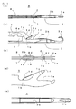
- FIGs. 1 illustrate structures of a compound needle 5 and two blades 1, 2 as an embodiment of the present invention.
- Figs. 2 illustrate operation states of the compound needle 5 in Figs. 1 .
- Figs. 3 illustrate operations of the blades 1, 2 in Fig. 1 .
- the blade 1 and the blade 2 are symmetric about a surface which is provided between the blade 1 and the blade 2 so as to be in parallel with the blade 1 and the blade 2. Parts corresponding to the blade 1 are also provided on the blade 2 even if the parts are not illustrated on the blade 2.
- the compound needle 5 is illustrated in a state where the compound needle 5 is accommodated in a needle groove formed on a needle bed of a flatbed knitting machine, the needle groove itself is not illustrated in the drawings. Note that the needle bed of the flatbed knitting machine is inclined upward toward a needle bad gap located at the front side of the needle groove and downward away from the needle bed gap, but the compound needle 5 is illustrated so as to be in a horizontal posture.
- a right side indicates a front side as the needle bed gap side and a left side indicates a rear side away from the needle bed gap.
- an upper side in the drawings indicates a direction that the compound needle 5 floats from the needle groove and a lower side in the drawings indicates a direction that the compound needle 5 sinks in the needle groove.
- Fig. 1(a) and Fig. 1(b) illustrate a plan structure and a front structure of a main part as the compound needle 5, respectively.
- a slider formed by coupling the two blades 1, 2 and a base body 4 is moved backward at the most level relatively with respect to the needle body 3. It is to be noted that although the blades 1, 2 and the base body 4 are coupled to each other at the left side in the drawings and the blades 1, 2 are moved by driving the base body 4, a coupling portion thereof is not illustrated.
- Fig. 1(c) and Fig. 1(d) illustrate plan structures of the blades 1, 2 at the front side thereof and a front structure of the blade 1 at the front side thereof, respectively.
- the blades 1, 2 according to the present embodiment have tongues 1a, 2a with no bending, and linear shaped portions 1b, 2b which are not curved are provided at the rear side of the tongues 1a, 2a, so that finishing shapes of the blades 1, 2 are stable and manufacturing thereof is easily performed.
- a stitch loop is retained on portions which extend to approximately horizontal direction in Fig. 1(d) , shoulder portions 1c, 2c are provided above the portions.
- shoulder portions 1c, 2c are provided above the portions.
- guiding portions 1d, 2d are provided to expand to outside.
- the guiding portion 1d is pressed to the lower side by a guiding portion presser 3c provided on the needle body 3.
- an engaging protrusion 1e is vertically provided on the blade 1.
- the engaging protrusion 1e is inserted into an engaging concave 4a provided on the base body 4 in a state where the blade 1 and the base body 4 are coupled to each other.
- an upper portion of the blade 1 can be restricted from displacing to outside with the coupling.
- Contacting portions 1f, 2f are also provided on the shoulder portions 1c, 2c at the front end side.
- the contacting portions 1f, 2f which are opposed to each other are bent inward such that front ends thereof make close to and contact with each other and a state where a space is generated between the tongues 1a, 2a is kept.
- the linear shaped portions 1b, 2b make slide contact with side walls of the blade groove 3b and the front ends of the contacting portions 1f, 2f make contact with each other at a position in the vicinity of the tongues 1a, 2a, so that a centering effect can be obtained even if the tongues 1a, 2a are not made contact with each other.
- a space between the tongues 1a, 2a can be made larger toward the front ends thereof by providing inclination on the inner sides of the front ends of the tongues 1a, 2a, such that thicknesses of the tongues 1a, 2a are made smaller toward the front ends. Further, if the tongues 1a, 2a are curved outward, the space between the tongues 1a, 2a can be further made larger toward the front ends thereof. Increase in the space between the tongues 1a, 2a on the front ends thereof makes it possible to enhance opening/closing accuracy of the hook 3a.
- Fig. 1(e) illustrates a plan structure of a front portion of the needle body 3.
- the single blade groove 3b of the present embodiment accommodates the two blades 1, 2, however, two grooves may be provided and each of the blades 1, 2 may be individually accommodated in each of the grooves as in Patent Literature 3.
- outside surfaces of the blades 1, 2 can be made slide contact with outside walls of the blade grooves and spaces can be generated between inside surfaces and inside walls, therefore sliding resistance can be made small and opening/closing accuracy of the hook 3a can be enhanced even with a simple structure.
- Fig. 2(a) and Fig. 2(b) illustrate a state where the blades 1, 2 are moved forward with respect to the needle body 3 from the backward state as illustrated in Fig. 1(a) and Fig. 1(b) and an aperture of the hook 3a is closed with the front ends of the tongues 1a, 2a.
- the aperture of the hook 3a is opened and the needle body 3 is moved forward with respect to the blades 1, 2 such that knitting yarns are supplied to the hook 3a advancing to the needle bed gap. If the stitch loop has been already formed on the hook 3a, the stitch loop is relatively moved backward with the forward movement of the needle body 3 and moves onto the tongues 1a, 2a.
- the stitch loop retained on the tongues 1a, 2a is knocked over and separated from the tongues 1a, 2a.
- the front ends of the contacting portions 1f, 2f are made contact with each other, so that the front ends of the tongues 1a, 2a make contact with the opening end of the hook 3a so as to reliably close the aperture of the hook 3a without positional deviation and lateral displacement.
- Fig. 2(c) and Fig. 2(d) illustrate a state where the tongues 1a, 2a are moved forward beyond the position of the hook 3a.
- the front portions of the blades 1, 2 on which the tongues 1a, 2a are formed are separated into both sides of the hook 3a and are moved forward.
- the lower portions of the blades 1, 2 which are accommodated in the blade groove 3b correspond to the linear shaped portions 1b, 2b having no curved portions, so that the blades 1, 2 can be moved forward in a state where sliding resistance between the linear shaped portions 1b, 2b and the side walls of the blade groove 3b is small.
- Fig. 3 illustrates operation states of the blades 1, 2 in the present embodiment. That is to say, Fig. 3(a) illustrates a state where the blades 1, 2 are arranged in parallel. Fig. 3(b) illustrates a state immediately before the blades 1, 2 close the aperture of the hook 3a. Fig. 3(c) illustrates a state where the blades 1, 2 close the aperture of the hook 3a and are further moved forward to open between the tongues 1a, 2a.
- the blades 1, 2 are arranged in parallel in an approximately linear form, and only the contacting portions 1f, 2f are bent inward and the front ends thereof make contact with each other, therefore the entire rigidity is kept so as to prevent the positional deviation and the lateral displacement.
- a space W between the outside surfaces of the blades 1, 2 is kept to be equivalent to the width of the blade groove 3b.
- the insides of the tongues 1a, 2a and the outsides of the hook 3a make contact with each other by a length L in a state where the tongues 1a, 2a on the blades 1, 2 are opened by the hook 3a.
- precompression in the direction of closing between the tongues 1a, 2a is small and the contact length L is ensured sufficient so that resistance does not become large when opening between the blades 1, 2.
- the contacting portions 1f, 2f are formed by bending the front ends of the shoulder portions 1c, 2c, however, the contacting portions can be provided by using another method such as embossing.
Landscapes
- Engineering & Computer Science (AREA)
- Textile Engineering (AREA)
- Knitting Machines (AREA)
Applications Claiming Priority (1)
| Application Number | Priority Date | Filing Date | Title |
|---|---|---|---|
| JP2010139816A JP5525344B2 (ja) | 2010-06-18 | 2010-06-18 | 横編機の複合針 |
Publications (3)
| Publication Number | Publication Date |
|---|---|
| EP2397589A2 true EP2397589A2 (fr) | 2011-12-21 |
| EP2397589A3 EP2397589A3 (fr) | 2012-11-14 |
| EP2397589B1 EP2397589B1 (fr) | 2015-10-21 |
Family
ID=44654559
Family Applications (1)
| Application Number | Title | Priority Date | Filing Date |
|---|---|---|---|
| EP11005005.1A Active EP2397589B1 (fr) | 2010-06-18 | 2011-06-20 | Aiguille de type compound pour les machines à tricoter rectiligne |
Country Status (4)
| Country | Link |
|---|---|
| EP (1) | EP2397589B1 (fr) |
| JP (1) | JP5525344B2 (fr) |
| KR (1) | KR101516156B1 (fr) |
| CN (1) | CN102286842B (fr) |
Cited By (4)
| Publication number | Priority date | Publication date | Assignee | Title |
|---|---|---|---|---|
| CN109629099A (zh) * | 2019-02-22 | 2019-04-16 | 泉州领布机械科技有限公司 | 新型毛绒多功能一体机 |
| EP3702505A1 (fr) * | 2019-02-28 | 2020-09-02 | Ningbo Cixing Co., Ltd. | Aiguille à coulisse dans une machine à tricoter rectiligne |
| EP3702506A1 (fr) * | 2019-02-28 | 2020-09-02 | Ningbo Cixing Co., Ltd. | Aiguille à coulisse pour une machine à tricoter rectiligne |
| EP3779009A1 (fr) * | 2019-08-13 | 2021-02-17 | Ningbo Cixing Co., Ltd. | Aiguille à coulisse de machine à tricoter rectiligne |
Families Citing this family (2)
| Publication number | Priority date | Publication date | Assignee | Title |
|---|---|---|---|---|
| CN103334223A (zh) * | 2013-07-04 | 2013-10-02 | 宁波慈星股份有限公司 | 一种用于横编机的织针 |
| CN104928841A (zh) * | 2015-07-07 | 2015-09-23 | 汕头市连兴实业有限公司 | 一种新型复合针 |
Citations (3)
| Publication number | Priority date | Publication date | Assignee | Title |
|---|---|---|---|---|
| JP3232075B2 (ja) | 1999-03-26 | 2001-11-26 | グロッツ−ベッケルト・カーゲー | 複合針 |
| JP3379947B2 (ja) | 1999-04-15 | 2003-02-24 | 株式会社島精機製作所 | 編機の複合針 |
| JP3532897B2 (ja) | 1999-10-27 | 2004-05-31 | 株式会社島精機製作所 | 複合針 |
Family Cites Families (10)
| Publication number | Priority date | Publication date | Assignee | Title |
|---|---|---|---|---|
| JPH03119160A (ja) * | 1989-10-03 | 1991-05-21 | Shima Seiki Seisakusho:Kk | コンパウンドニードル |
| DE4100931A1 (de) * | 1991-01-15 | 1992-07-16 | Groz & Soehne Theodor | Schiebernadel, insbesondere fuer strickmaschinen |
| DE4430705A1 (de) * | 1994-08-30 | 1996-03-07 | Scheller Gmbh | Strickmaschine |
| US5937673A (en) * | 1997-05-01 | 1999-08-17 | Shima Seiki Manufacturing, Ltd. | Compound needle of a flat knitting machine |
| CH691543A5 (fr) * | 1997-05-27 | 2001-08-15 | Steiger Sa Atelier Constr | Aiguille à coulisse pour machine à tricoter. |
| TW477845B (en) * | 1999-10-27 | 2002-03-01 | Shima Seiki Mfg | Guide mechanism of knitting member and compound needle assembling the guide mechanism therein |
| DE10130365C1 (de) * | 2001-06-23 | 2003-01-23 | Groz Beckert Kg | Schiebernadel mit verbessertem Schieber |
| AU2003289227A1 (en) * | 2002-12-20 | 2004-07-14 | Shima Seiki Manufacturing, Ltd. | Compound needle |
| JP4348286B2 (ja) * | 2004-12-09 | 2009-10-21 | 株式会社島精機製作所 | 横編機 |
| WO2007037285A1 (fr) * | 2005-09-28 | 2007-04-05 | Shima Seiki Manufacturing Limited | Métier à mailles cueillies comportant un guide-fil mobile |
-
2010
- 2010-06-18 JP JP2010139816A patent/JP5525344B2/ja active Active
-
2011
- 2011-06-09 KR KR1020110055435A patent/KR101516156B1/ko active Active
- 2011-06-17 CN CN201110162813.7A patent/CN102286842B/zh active Active
- 2011-06-20 EP EP11005005.1A patent/EP2397589B1/fr active Active
Patent Citations (3)
| Publication number | Priority date | Publication date | Assignee | Title |
|---|---|---|---|---|
| JP3232075B2 (ja) | 1999-03-26 | 2001-11-26 | グロッツ−ベッケルト・カーゲー | 複合針 |
| JP3379947B2 (ja) | 1999-04-15 | 2003-02-24 | 株式会社島精機製作所 | 編機の複合針 |
| JP3532897B2 (ja) | 1999-10-27 | 2004-05-31 | 株式会社島精機製作所 | 複合針 |
Cited By (5)
| Publication number | Priority date | Publication date | Assignee | Title |
|---|---|---|---|---|
| CN109629099A (zh) * | 2019-02-22 | 2019-04-16 | 泉州领布机械科技有限公司 | 新型毛绒多功能一体机 |
| CN109629099B (zh) * | 2019-02-22 | 2024-03-01 | 泉州领布机械科技有限公司 | 新型毛绒多功能一体机 |
| EP3702505A1 (fr) * | 2019-02-28 | 2020-09-02 | Ningbo Cixing Co., Ltd. | Aiguille à coulisse dans une machine à tricoter rectiligne |
| EP3702506A1 (fr) * | 2019-02-28 | 2020-09-02 | Ningbo Cixing Co., Ltd. | Aiguille à coulisse pour une machine à tricoter rectiligne |
| EP3779009A1 (fr) * | 2019-08-13 | 2021-02-17 | Ningbo Cixing Co., Ltd. | Aiguille à coulisse de machine à tricoter rectiligne |
Also Published As
| Publication number | Publication date |
|---|---|
| JP5525344B2 (ja) | 2014-06-18 |
| CN102286842B (zh) | 2015-01-28 |
| JP2012001858A (ja) | 2012-01-05 |
| CN102286842A (zh) | 2011-12-21 |
| EP2397589A3 (fr) | 2012-11-14 |
| KR20110138157A (ko) | 2011-12-26 |
| EP2397589B1 (fr) | 2015-10-21 |
| KR101516156B1 (ko) | 2015-04-30 |
Similar Documents
| Publication | Publication Date | Title |
|---|---|---|
| EP2397589B1 (fr) | Aiguille de type compound pour les machines à tricoter rectiligne | |
| EP2397590B1 (fr) | Aiguille à coulisseau pour machine à tricoter rectiligne | |
| EP2894245B1 (fr) | Machine à tricoter rectiligne équipé d'une dispositif de platine | |
| US6422045B1 (en) | Compound needle of knitting machine | |
| EP2423363B1 (fr) | Metier a mailles cueillies equipe d'une platine mobile | |
| KR101062665B1 (ko) | 복합바늘 | |
| US20230216234A1 (en) | Connector Cage Assembly | |
| CN114502858B (zh) | 啮合链条及可动体移动装置 | |
| EP2415917B1 (fr) | Aiguille de type compound pour machine à tricoter rectiligne | |
| EP2354285B1 (fr) | Dispositif de manipulation de fil à tricoter pour machine à tricoter à plat | |
| EP1640489B1 (fr) | Aiguille compound | |
| KR100585262B1 (ko) | 복합바늘 | |
| EP2372003A1 (fr) | Dispositif de came pour aiguille de réception de transfert | |
| JP5632277B2 (ja) | 横編機の複合針 | |
| KR20130061057A (ko) | 횡편기의 복합바늘 | |
| EP3719191B1 (fr) | Métier à tricoter rectiligne | |
| KR101569012B1 (ko) | 가동싱커를 구비하는 횡편기 | |
| EP2551393B1 (fr) | Aiguille complexe, métier à mailles cueillies | |
| CN203339368U (zh) | 连接器 | |
| EP2458051A2 (fr) | Aiguille de type compound pour machine à tricoter rectiligne | |
| WO2024253165A1 (fr) | Machine à tricoter plate pourvue d'un poussoir de transfert, et poussoir de transfert | |
| CN204434899U (zh) | 横机的复合针 | |
| JPWO2010010681A1 (ja) | 編針駆動用カムおよび横編機 | |
| JP2012132126A (ja) | 横編機の複合針 | |
| KR20090067967A (ko) | 금형조립체 |
Legal Events
| Date | Code | Title | Description |
|---|---|---|---|
| AK | Designated contracting states |
Kind code of ref document: A2 Designated state(s): AL AT BE BG CH CY CZ DE DK EE ES FI FR GB GR HR HU IE IS IT LI LT LU LV MC MK MT NL NO PL PT RO RS SE SI SK SM TR |
|
| AX | Request for extension of the european patent |
Extension state: BA ME |
|
| PUAI | Public reference made under article 153(3) epc to a published international application that has entered the european phase |
Free format text: ORIGINAL CODE: 0009012 |
|
| PUAL | Search report despatched |
Free format text: ORIGINAL CODE: 0009013 |
|
| AK | Designated contracting states |
Kind code of ref document: A3 Designated state(s): AL AT BE BG CH CY CZ DE DK EE ES FI FR GB GR HR HU IE IS IT LI LT LU LV MC MK MT NL NO PL PT RO RS SE SI SK SM TR |
|
| AX | Request for extension of the european patent |
Extension state: BA ME |
|
| RIC1 | Information provided on ipc code assigned before grant |
Ipc: D04B 35/06 20060101AFI20121008BHEP |
|
| 17P | Request for examination filed |
Effective date: 20130123 |
|
| GRAP | Despatch of communication of intention to grant a patent |
Free format text: ORIGINAL CODE: EPIDOSNIGR1 |
|
| GRAJ | Information related to disapproval of communication of intention to grant by the applicant or resumption of examination proceedings by the epo deleted |
Free format text: ORIGINAL CODE: EPIDOSDIGR1 |
|
| GRAP | Despatch of communication of intention to grant a patent |
Free format text: ORIGINAL CODE: EPIDOSNIGR1 |
|
| INTG | Intention to grant announced |
Effective date: 20150413 |
|
| INTG | Intention to grant announced |
Effective date: 20150430 |
|
| GRAS | Grant fee paid |
Free format text: ORIGINAL CODE: EPIDOSNIGR3 |
|
| GRAA | (expected) grant |
Free format text: ORIGINAL CODE: 0009210 |
|
| AK | Designated contracting states |
Kind code of ref document: B1 Designated state(s): AL AT BE BG CH CY CZ DE DK EE ES FI FR GB GR HR HU IE IS IT LI LT LU LV MC MK MT NL NO PL PT RO RS SE SI SK SM TR |
|
| REG | Reference to a national code |
Ref country code: GB Ref legal event code: FG4D Ref country code: NL Ref legal event code: MP Effective date: 20151021 |
|
| REG | Reference to a national code |
Ref country code: CH Ref legal event code: EP |
|
| REG | Reference to a national code |
Ref country code: AT Ref legal event code: REF Ref document number: 756678 Country of ref document: AT Kind code of ref document: T Effective date: 20151115 |
|
| REG | Reference to a national code |
Ref country code: IE Ref legal event code: FG4D |
|
| REG | Reference to a national code |
Ref country code: DE Ref legal event code: R096 Ref document number: 602011020716 Country of ref document: DE |
|
| REG | Reference to a national code |
Ref country code: LT Ref legal event code: MG4D |
|
| REG | Reference to a national code |
Ref country code: AT Ref legal event code: MK05 Ref document number: 756678 Country of ref document: AT Kind code of ref document: T Effective date: 20151021 |
|
| PG25 | Lapsed in a contracting state [announced via postgrant information from national office to epo] |
Ref country code: ES Free format text: LAPSE BECAUSE OF FAILURE TO SUBMIT A TRANSLATION OF THE DESCRIPTION OR TO PAY THE FEE WITHIN THE PRESCRIBED TIME-LIMIT Effective date: 20151021 Ref country code: NL Free format text: LAPSE BECAUSE OF FAILURE TO SUBMIT A TRANSLATION OF THE DESCRIPTION OR TO PAY THE FEE WITHIN THE PRESCRIBED TIME-LIMIT Effective date: 20151021 Ref country code: LT Free format text: LAPSE BECAUSE OF FAILURE TO SUBMIT A TRANSLATION OF THE DESCRIPTION OR TO PAY THE FEE WITHIN THE PRESCRIBED TIME-LIMIT Effective date: 20151021 Ref country code: IS Free format text: LAPSE BECAUSE OF FAILURE TO SUBMIT A TRANSLATION OF THE DESCRIPTION OR TO PAY THE FEE WITHIN THE PRESCRIBED TIME-LIMIT Effective date: 20160221 Ref country code: HR Free format text: LAPSE BECAUSE OF FAILURE TO SUBMIT A TRANSLATION OF THE DESCRIPTION OR TO PAY THE FEE WITHIN THE PRESCRIBED TIME-LIMIT Effective date: 20151021 Ref country code: NO Free format text: LAPSE BECAUSE OF FAILURE TO SUBMIT A TRANSLATION OF THE DESCRIPTION OR TO PAY THE FEE WITHIN THE PRESCRIBED TIME-LIMIT Effective date: 20160121 |
|
| PG25 | Lapsed in a contracting state [announced via postgrant information from national office to epo] |
Ref country code: PT Free format text: LAPSE BECAUSE OF FAILURE TO SUBMIT A TRANSLATION OF THE DESCRIPTION OR TO PAY THE FEE WITHIN THE PRESCRIBED TIME-LIMIT Effective date: 20160222 Ref country code: PL Free format text: LAPSE BECAUSE OF FAILURE TO SUBMIT A TRANSLATION OF THE DESCRIPTION OR TO PAY THE FEE WITHIN THE PRESCRIBED TIME-LIMIT Effective date: 20151021 Ref country code: LV Free format text: LAPSE BECAUSE OF FAILURE TO SUBMIT A TRANSLATION OF THE DESCRIPTION OR TO PAY THE FEE WITHIN THE PRESCRIBED TIME-LIMIT Effective date: 20151021 Ref country code: FI Free format text: LAPSE BECAUSE OF FAILURE TO SUBMIT A TRANSLATION OF THE DESCRIPTION OR TO PAY THE FEE WITHIN THE PRESCRIBED TIME-LIMIT Effective date: 20151021 Ref country code: AT Free format text: LAPSE BECAUSE OF FAILURE TO SUBMIT A TRANSLATION OF THE DESCRIPTION OR TO PAY THE FEE WITHIN THE PRESCRIBED TIME-LIMIT Effective date: 20151021 Ref country code: GR Free format text: LAPSE BECAUSE OF FAILURE TO SUBMIT A TRANSLATION OF THE DESCRIPTION OR TO PAY THE FEE WITHIN THE PRESCRIBED TIME-LIMIT Effective date: 20160122 Ref country code: SE Free format text: LAPSE BECAUSE OF FAILURE TO SUBMIT A TRANSLATION OF THE DESCRIPTION OR TO PAY THE FEE WITHIN THE PRESCRIBED TIME-LIMIT Effective date: 20151021 Ref country code: RS Free format text: LAPSE BECAUSE OF FAILURE TO SUBMIT A TRANSLATION OF THE DESCRIPTION OR TO PAY THE FEE WITHIN THE PRESCRIBED TIME-LIMIT Effective date: 20151021 |
|
| REG | Reference to a national code |
Ref country code: DE Ref legal event code: R097 Ref document number: 602011020716 Country of ref document: DE |
|
| PG25 | Lapsed in a contracting state [announced via postgrant information from national office to epo] |
Ref country code: CZ Free format text: LAPSE BECAUSE OF FAILURE TO SUBMIT A TRANSLATION OF THE DESCRIPTION OR TO PAY THE FEE WITHIN THE PRESCRIBED TIME-LIMIT Effective date: 20151021 |
|
| PLBE | No opposition filed within time limit |
Free format text: ORIGINAL CODE: 0009261 |
|
| STAA | Information on the status of an ep patent application or granted ep patent |
Free format text: STATUS: NO OPPOSITION FILED WITHIN TIME LIMIT |
|
| PG25 | Lapsed in a contracting state [announced via postgrant information from national office to epo] |
Ref country code: RO Free format text: LAPSE BECAUSE OF FAILURE TO SUBMIT A TRANSLATION OF THE DESCRIPTION OR TO PAY THE FEE WITHIN THE PRESCRIBED TIME-LIMIT Effective date: 20151021 Ref country code: DK Free format text: LAPSE BECAUSE OF FAILURE TO SUBMIT A TRANSLATION OF THE DESCRIPTION OR TO PAY THE FEE WITHIN THE PRESCRIBED TIME-LIMIT Effective date: 20151021 Ref country code: EE Free format text: LAPSE BECAUSE OF FAILURE TO SUBMIT A TRANSLATION OF THE DESCRIPTION OR TO PAY THE FEE WITHIN THE PRESCRIBED TIME-LIMIT Effective date: 20151021 Ref country code: SM Free format text: LAPSE BECAUSE OF FAILURE TO SUBMIT A TRANSLATION OF THE DESCRIPTION OR TO PAY THE FEE WITHIN THE PRESCRIBED TIME-LIMIT Effective date: 20151021 Ref country code: SK Free format text: LAPSE BECAUSE OF FAILURE TO SUBMIT A TRANSLATION OF THE DESCRIPTION OR TO PAY THE FEE WITHIN THE PRESCRIBED TIME-LIMIT Effective date: 20151021 |
|
| 26N | No opposition filed |
Effective date: 20160722 |
|
| PG25 | Lapsed in a contracting state [announced via postgrant information from national office to epo] |
Ref country code: SI Free format text: LAPSE BECAUSE OF FAILURE TO SUBMIT A TRANSLATION OF THE DESCRIPTION OR TO PAY THE FEE WITHIN THE PRESCRIBED TIME-LIMIT Effective date: 20151021 |
|
| PG25 | Lapsed in a contracting state [announced via postgrant information from national office to epo] |
Ref country code: BE Free format text: LAPSE BECAUSE OF FAILURE TO SUBMIT A TRANSLATION OF THE DESCRIPTION OR TO PAY THE FEE WITHIN THE PRESCRIBED TIME-LIMIT Effective date: 20151021 |
|
| PG25 | Lapsed in a contracting state [announced via postgrant information from national office to epo] |
Ref country code: MC Free format text: LAPSE BECAUSE OF FAILURE TO SUBMIT A TRANSLATION OF THE DESCRIPTION OR TO PAY THE FEE WITHIN THE PRESCRIBED TIME-LIMIT Effective date: 20151021 |
|
| REG | Reference to a national code |
Ref country code: CH Ref legal event code: PL |
|
| GBPC | Gb: european patent ceased through non-payment of renewal fee |
Effective date: 20160620 |
|
| REG | Reference to a national code |
Ref country code: IE Ref legal event code: MM4A |
|
| REG | Reference to a national code |
Ref country code: FR Ref legal event code: ST Effective date: 20170228 |
|
| PG25 | Lapsed in a contracting state [announced via postgrant information from national office to epo] |
Ref country code: FR Free format text: LAPSE BECAUSE OF NON-PAYMENT OF DUE FEES Effective date: 20160630 Ref country code: CH Free format text: LAPSE BECAUSE OF NON-PAYMENT OF DUE FEES Effective date: 20160630 Ref country code: LI Free format text: LAPSE BECAUSE OF NON-PAYMENT OF DUE FEES Effective date: 20160630 |
|
| PG25 | Lapsed in a contracting state [announced via postgrant information from national office to epo] |
Ref country code: GB Free format text: LAPSE BECAUSE OF NON-PAYMENT OF DUE FEES Effective date: 20160620 Ref country code: IE Free format text: LAPSE BECAUSE OF NON-PAYMENT OF DUE FEES Effective date: 20160620 |
|
| PG25 | Lapsed in a contracting state [announced via postgrant information from national office to epo] |
Ref country code: HU Free format text: LAPSE BECAUSE OF FAILURE TO SUBMIT A TRANSLATION OF THE DESCRIPTION OR TO PAY THE FEE WITHIN THE PRESCRIBED TIME-LIMIT; INVALID AB INITIO Effective date: 20110620 Ref country code: CY Free format text: LAPSE BECAUSE OF FAILURE TO SUBMIT A TRANSLATION OF THE DESCRIPTION OR TO PAY THE FEE WITHIN THE PRESCRIBED TIME-LIMIT Effective date: 20151021 |
|
| PG25 | Lapsed in a contracting state [announced via postgrant information from national office to epo] |
Ref country code: MK Free format text: LAPSE BECAUSE OF FAILURE TO SUBMIT A TRANSLATION OF THE DESCRIPTION OR TO PAY THE FEE WITHIN THE PRESCRIBED TIME-LIMIT Effective date: 20151021 Ref country code: MT Free format text: LAPSE BECAUSE OF NON-PAYMENT OF DUE FEES Effective date: 20160630 Ref country code: TR Free format text: LAPSE BECAUSE OF FAILURE TO SUBMIT A TRANSLATION OF THE DESCRIPTION OR TO PAY THE FEE WITHIN THE PRESCRIBED TIME-LIMIT Effective date: 20151021 Ref country code: LU Free format text: LAPSE BECAUSE OF NON-PAYMENT OF DUE FEES Effective date: 20160620 |
|
| PG25 | Lapsed in a contracting state [announced via postgrant information from national office to epo] |
Ref country code: BG Free format text: LAPSE BECAUSE OF FAILURE TO SUBMIT A TRANSLATION OF THE DESCRIPTION OR TO PAY THE FEE WITHIN THE PRESCRIBED TIME-LIMIT Effective date: 20151021 |
|
| PG25 | Lapsed in a contracting state [announced via postgrant information from national office to epo] |
Ref country code: AL Free format text: LAPSE BECAUSE OF FAILURE TO SUBMIT A TRANSLATION OF THE DESCRIPTION OR TO PAY THE FEE WITHIN THE PRESCRIBED TIME-LIMIT Effective date: 20151021 |
|
| PGFP | Annual fee paid to national office [announced via postgrant information from national office to epo] |
Ref country code: DE Payment date: 20250402 Year of fee payment: 15 |
|
| PGFP | Annual fee paid to national office [announced via postgrant information from national office to epo] |
Ref country code: IT Payment date: 20250522 Year of fee payment: 15 |