EP2397639A2 - Porte à tambour - Google Patents
Porte à tambour Download PDFInfo
- Publication number
- EP2397639A2 EP2397639A2 EP11004402A EP11004402A EP2397639A2 EP 2397639 A2 EP2397639 A2 EP 2397639A2 EP 11004402 A EP11004402 A EP 11004402A EP 11004402 A EP11004402 A EP 11004402A EP 2397639 A2 EP2397639 A2 EP 2397639A2
- Authority
- EP
- European Patent Office
- Prior art keywords
- drive
- revolving door
- turnstile
- axis
- floor
- Prior art date
- Legal status (The legal status is an assumption and is not a legal conclusion. Google has not performed a legal analysis and makes no representation as to the accuracy of the status listed.)
- Granted
Links
Images

Classifications
-
- E—FIXED CONSTRUCTIONS
- E05—LOCKS; KEYS; WINDOW OR DOOR FITTINGS; SAFES
- E05F—DEVICES FOR MOVING WINGS INTO OPEN OR CLOSED POSITION; CHECKS FOR WINGS; WING FITTINGS NOT OTHERWISE PROVIDED FOR, CONCERNED WITH THE FUNCTIONING OF THE WING
- E05F15/00—Power-operated mechanisms for wings
- E05F15/60—Power-operated mechanisms for wings using electrical actuators
- E05F15/603—Power-operated mechanisms for wings using electrical actuators using rotary electromotors
- E05F15/608—Power-operated mechanisms for wings using electrical actuators using rotary electromotors for revolving wings
-
- E—FIXED CONSTRUCTIONS
- E05—LOCKS; KEYS; WINDOW OR DOOR FITTINGS; SAFES
- E05Y—INDEXING SCHEME ASSOCIATED WITH SUBCLASSES E05D AND E05F, RELATING TO CONSTRUCTION ELEMENTS, ELECTRIC CONTROL, POWER SUPPLY, POWER SIGNAL OR TRANSMISSION, USER INTERFACES, MOUNTING OR COUPLING, DETAILS, ACCESSORIES, AUXILIARY OPERATIONS NOT OTHERWISE PROVIDED FOR, APPLICATION THEREOF
- E05Y2600/00—Mounting or coupling arrangements for elements provided for in this subclass
- E05Y2600/10—Adjustable
-
- E—FIXED CONSTRUCTIONS
- E05—LOCKS; KEYS; WINDOW OR DOOR FITTINGS; SAFES
- E05Y—INDEXING SCHEME ASSOCIATED WITH SUBCLASSES E05D AND E05F, RELATING TO CONSTRUCTION ELEMENTS, ELECTRIC CONTROL, POWER SUPPLY, POWER SIGNAL OR TRANSMISSION, USER INTERFACES, MOUNTING OR COUPLING, DETAILS, ACCESSORIES, AUXILIARY OPERATIONS NOT OTHERWISE PROVIDED FOR, APPLICATION THEREOF
- E05Y2600/00—Mounting or coupling arrangements for elements provided for in this subclass
- E05Y2600/40—Mounting location; Visibility of the elements
- E05Y2600/452—Mounting location; Visibility of the elements in or on the floor or wall
-
- E—FIXED CONSTRUCTIONS
- E05—LOCKS; KEYS; WINDOW OR DOOR FITTINGS; SAFES
- E05Y—INDEXING SCHEME ASSOCIATED WITH SUBCLASSES E05D AND E05F, RELATING TO CONSTRUCTION ELEMENTS, ELECTRIC CONTROL, POWER SUPPLY, POWER SIGNAL OR TRANSMISSION, USER INTERFACES, MOUNTING OR COUPLING, DETAILS, ACCESSORIES, AUXILIARY OPERATIONS NOT OTHERWISE PROVIDED FOR, APPLICATION THEREOF
- E05Y2800/00—Details, accessories and auxiliary operations not otherwise provided for
- E05Y2800/26—Form or shape
-
- E—FIXED CONSTRUCTIONS
- E05—LOCKS; KEYS; WINDOW OR DOOR FITTINGS; SAFES
- E05Y—INDEXING SCHEME ASSOCIATED WITH SUBCLASSES E05D AND E05F, RELATING TO CONSTRUCTION ELEMENTS, ELECTRIC CONTROL, POWER SUPPLY, POWER SIGNAL OR TRANSMISSION, USER INTERFACES, MOUNTING OR COUPLING, DETAILS, ACCESSORIES, AUXILIARY OPERATIONS NOT OTHERWISE PROVIDED FOR, APPLICATION THEREOF
- E05Y2900/00—Application of doors, windows, wings or fittings thereof
- E05Y2900/10—Application of doors, windows, wings or fittings thereof for buildings or parts thereof
Definitions
- the invention relates to an automated, d. H. revolving door provided with a motor drive.
- From the EP 2 072 737 A2 is a revolving door known, which has a motor drive in a ceiling construction above the turnstile of the revolving door system.
- the turnstile is formed by means of a rotary column with attached revolving door wings.
- a drive motor is operatively connected via an output shaft and a deflection gear with the rotary column.
- the output shaft extends approximately perpendicular to the longitudinal extent of the rotary column.
- the object of the invention is to reduce the disadvantages of the prior art.
- a revolving door according to the invention has a drive which is rotationally drivingly connected to a turnstile of the revolving door of this turnstile.
- the drive comprises a drive motor designed as a multi-pole electric motor, whose axis of rotation runs parallel or coaxial with the axis of rotation of the turnstile, and which has a height equal to or smaller than 80 mm.
- the drive according to the invention in a bottom portion of the revolving door, ie underfloor can be arranged so that no work on the shell of the building must take place, in which the revolving door should be integrated.
- the drive has a height equal to or less than 60 mm.
- the receiving space is thus a portion of the floor in which the drive according to the invention is to be used.
- the bottom section is thus arranged between the turnstile of the revolving door and a shell of a building. The bottom section rests on the shell or is arranged above this shell.
- the revolving door preferably further comprises an adjusting device which is adapted to change the insertion position of the drive in the ground. This makes it possible to align the drive so the turnstile that both elements can be brought into the aforementioned drive-active connection.
- the adjustment allows a height adjustment of the drive in the ground, whereby the drive can be arranged regardless of the depth of the bottom portion at the correct distance from the turnstile.
- the adjustment device allows tilt adjustment of the drive with respect to the ground.
- the drive can also be used with respect to the turnstile inclined floors without special precautions for the operative connection between the turnstile and the drive are necessary.
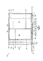
- FIG. 1 shows a revolving door 100 according to a first embodiment of the invention.
- the revolving door 100 is designed free-standing. Ie. she is as an independent part integrated into a not shown building.
- the revolving door 100 comprises a turnstile, which is formed by means of a rotary column 105, to which a plurality of rotary vanes 120 are fastened in a known manner.
- the rotary blades 120 are exemplarily designed as glass door wings, each comprising a frame profile 122, in which a respective glass panel 121 is inserted.
- the rotary column 105 with the rotatably mounted thereon rotary blades 120 is mounted on a drive 130 and recorded freely rotatable in the revolving door 100.
- the drive 130 is recessed in a bottom 10 of the housing.
- the floor 10 substantially comprises a shell 12 and a cover layer 13, in which a receiving space or a receptacle 11 for the drive 130 is formed.
- the cover layer 13 is simply omitted in the region of the receptacle 11.
- the cover layer 13 is thinned in this area.
- the receptacle 11 can also be formed by means of a recessed into the ground, towards the revolving door 100 open box.
- the cover layer 13 may be a screed spread on the shell 12.
- the drive 130 comprises a housing 131 here in the form of a pot-like lid, which is placed on a bottom plate 132, which in turn is here supported by three visible support bolts 136 on the lower bottom of the receiving box 107 and thus on the shell 12.
- the support screws 136 thus allow for a height adjustment of the drive 130, ie a vertical adjustment in FIG. 1 if all support screws 136 are rotated simultaneously.
- the drive 130 has on its upper side a cover plate 137 which protects the drive 130 from contamination in the region of the operative connection with the rotary column 105.
- the drive 130 is in the upper area laterally in FIG. 1 surrounded by another cover plate 106 which closes the rest, pointing in the direction of revolving door 100 area of the receiving box 107 dirt-proof, the cover plate 106 is supported in the region of the drive 130 advantageously on support members 133 which are in turn supported here on the bottom plate 132. This ensures a safe shaft pitch of the cover plate 106 over the entire area.
- the cover plate 106 is sealingly placed on upper edge portions of the receiving box 107.
- the latter is coupled via one or more lines 104 to a panel 140, which is coupled via another line or lines 104 to a sensor 103 arranged in the upper area of the revolving door 100.
- the sensor 103 may also be omitted.
- the sensor 103 is used here in a ceiling 110 or ceiling construction of the revolving door 100. Outside to the right and to the left in FIG. 1 the revolving door 100 is enclosed by means of drum walls 102.
- the panel 140 is disposed in the left drum wall 102 of the revolving door 100, and exemplarily, regardless of any activation by the sensor 103, allows the revolving door 100 to be stopped or moved.
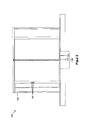
- FIG. 2 shows the revolving door 100 of FIG. 1 wherein the drive 130 is visible only through the housing 131 and the upper cover plate 137.
- the not explicitly designated panel 140 includes in the example shown three elements 141, which are formed for example as 55 mm inserts and can have any configuration (switch, display, sensor, ).
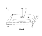
- FIG. 3 shows the drive 130 in greater detail.
- the bottom plate 132 on which both the support elements 133 and the housing 131 are mounted, can be seen particularly clearly.
- a shaft portion 134 is arranged, which is actively co-rotating with the turnstile not shown here.
- the shaft part 134 has a turnstile coupling section 135, for example in the form of a receiving opening with internal toothing.
- the shaft member 135 is frictionally received in the housing via a bearing or has the housing 131 a predetermined distance.
- protruding out of the shaft part 135 in the direction of the revolving door 100 is a protrusion, for example in the form of an outer quadrant, onto which the turnstile with a complementarily formed receptacle is mounted in a form-fitting manner.
- the cover plate 137 may be fastened or formed on the rotary column 105, also not shown, and the shaft part 135 sealingly surrounded, so that no or negligibly low risk of contamination exists in the region of the rotating parts.
- a multi-pole drive motor is provided as the drive motor.
- Whose stator preferably comprises electric coils, which are annularly fixed, for example, on the inner peripheral side of the housing 131 and interconnected in accordance with drive.
- the rotor or rotor of the drive motor is rotationally connected to the turnstile coupling 135 and has, for example, annularly arranged permanent magnets, which are arranged in such a way that they enter into electromagnetic drive interaction when the electric coils are energized therewith.
- the axis of rotation of the rotor or drive motor runs parallel or even coaxially to the axis of rotation of the turnstile coupling 135 and thus also to the axis of rotation of the rotary column 105 or of the entire turnstile.
- the rotational engagement can be formed by means of a speichenrad-, disc-like or otherwise shaped part which mechanically or physically rotatably coupled to the rotor or rotor with the turnstile coupling or connects.
- This type of drive motor has the advantage that the electromagnetic drive force is generated in a remote location from the motor rotation axis.
- the forces generated by the drive motor in the interaction region between the stator and the rotor are much lower than the torque to be applied to the motor shaft, turnstile clutch 135 or rotary column 105. This allows the use of shallow stators and rotors, whereby the inventive low height can be achieved.
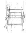
- FIG. 4 shows a revolving door 100 according to a second embodiment of the invention.
- the revolving door 100 like the first embodiment, in turn has an underfloor drive 130, which is connected to the Turnstile of the revolving door 100 is operatively connected.
- the turnstile is here formed by means of three glass door leaves 120, the frame profiles 122 are attached to the covered by them rotary column 105.
- the ceiling 110 of the revolving door 100 is formed by means of a circumferential, ring-shaped ceiling frame 111, which is intersected by a transverse strut 112. Between the frame 111 and the transverse strut 112, two glass plates 113, which are semicircular in cross section, are preferably used here.
- the rotary blades 120 equipped with glass panels 121 are in turn surrounded on both sides by two drum walls 102.
- the underfloor arranged drive 130 allows an extremely filigree ceiling 110 or ceiling construction. In particular, if no additional elements such as sensors and the like are required in the upper area, very visually appealing solutions are possible.
- such a revolving door 100 can be optically integrated into glass facades, which, as here, comprise glass panels 1, which can be arranged abutting one another, for example via seals or filigree struts 112, and a glass façade preferably extending to the floor 10 , Since above the revolving door 100 no more drive must be attached, this filigree can continue into the revolving door 100 inside, resulting in a very visually appealing overall impression.
- FIG. 5 shows a revolving door 100 according to a third embodiment of the invention.
- the revolving door 100 is formed like the previous embodiments. It therefore has a ceiling 110 with an annular ceiling frame 111.
- the revolving door 100 is enclosed on both sides by two posts 101, which are preferably located in the respective center of the respectively adjacent one Drum edge 102 are arranged.
- the underside, in turn, the drive 130 is arranged.
- the posts 101 and the crossbar 112 separate the panels 1 of the glass facade from each other.
- the invention is not limited to the previous embodiments.
- the ceiling construction 110 can be designed in various ways.
- the cross member 112 can be omitted.
- the annular ceiling frame 111 itself can be omitted, provided that the turnstile is received freely rotatably at its upper end, for example in a ceiling or the like. In that case, the ceiling 110 of the revolving door 100 could be at least partially open.
- the rotary vanes 120 may be formed in any embodiment, for example, thermally insulating. The same of course applies to the drum walls 102 of the revolving door 100.
- Essential to the invention is the extremely flat drive 130, which makes it possible to sink the drive 130 in the bottom 10, without the shell 12 would have to be processed.
Landscapes
- Power-Operated Mechanisms For Wings (AREA)
- Extensible Doors And Revolving Doors (AREA)
Applications Claiming Priority (1)
| Application Number | Priority Date | Filing Date | Title |
|---|---|---|---|
| DE102010024108A DE102010024108A1 (de) | 2010-06-17 | 2010-06-17 | Karuselltür |
Publications (3)
| Publication Number | Publication Date |
|---|---|
| EP2397639A2 true EP2397639A2 (fr) | 2011-12-21 |
| EP2397639A3 EP2397639A3 (fr) | 2014-06-25 |
| EP2397639B1 EP2397639B1 (fr) | 2017-03-22 |
Family
ID=44484007
Family Applications (1)
| Application Number | Title | Priority Date | Filing Date |
|---|---|---|---|
| EP11004402.1A Active EP2397639B1 (fr) | 2010-06-17 | 2011-05-30 | Porte à tambour |
Country Status (4)
| Country | Link |
|---|---|
| US (1) | US20120005961A1 (fr) |
| EP (1) | EP2397639B1 (fr) |
| CN (1) | CN102287111A (fr) |
| DE (1) | DE102010024108A1 (fr) |
Families Citing this family (13)
| Publication number | Priority date | Publication date | Assignee | Title |
|---|---|---|---|---|
| DE102013000421A1 (de) * | 2013-01-14 | 2014-07-17 | Dorma Gmbh & Co. Kg | Antriebseinheit für eine Karusselltür in einer flachen. scheibenförmigen Bauform |
| DE102013000416B4 (de) * | 2013-01-14 | 2016-10-06 | Dorma Deutschland Gmbh | Verfahren zur Anordnung einer Antriebseinheit in einer Karusselltür |
| DE102013000420A1 (de) | 2013-01-14 | 2014-07-17 | Dorma Gmbh & Co. Kg | Antriebseinheit für eine Karusselltür mit einer integrierten Blockier- und/oder Bremseinrichtung |
| DE102013000417A1 (de) | 2013-01-14 | 2014-07-17 | Dorma Gmbh & Co. Kg | Antriebseinheit, inbesondere für eine Karusseltür, mit einem elektronisch kommutierten Vielpolmotor |
| DE102013000422B4 (de) * | 2013-01-14 | 2021-03-25 | Dormakaba Deutschland Gmbh | Karusselltür mit einer bodenmontierten Antriebseinheit |
| DE102013000423B3 (de) | 2013-01-14 | 2014-03-13 | Dorma Gmbh & Co. Kg | Karusselltür mit einer an einem Glasdeckenelement angeordneten Antriebseinheit |
| DE102013000419A1 (de) | 2013-01-14 | 2014-07-17 | Dorma Gmbh & Co. Kg | Verfahren zur Anordnung einer Antriebseinheit an einem Deckenelement einer Karusselltür |
| CN105745689A (zh) | 2013-09-20 | 2016-07-06 | 挪佛麦迪哥股份公司 | 入口控制装置 |
| DE202013008332U1 (de) | 2013-09-20 | 2015-01-05 | Novomatic Ag | Zugangskontrollvorrichtung |
| DE102015008133A1 (de) | 2015-06-24 | 2016-12-29 | Landert Motoren Ag | Antriebseinheit für eine automatische Karusselltür |
| EP4107353B1 (fr) * | 2020-02-18 | 2025-09-03 | ASSA ABLOY Entrance Systems AB | Arrangement de montage de la porte tournante |
| WO2021175968A1 (fr) * | 2020-03-05 | 2021-09-10 | Assa Abloy Entrance Systems Ab | Ensemble porte tournante |
| DE102021116870B3 (de) * | 2021-06-30 | 2022-10-06 | Cambaum Gmbh | Schwenkantrieb |
Citations (1)
| Publication number | Priority date | Publication date | Assignee | Title |
|---|---|---|---|---|
| EP2072737A2 (fr) | 2007-12-20 | 2009-06-24 | GEZE GmbH | Installation de porte tournante automatique et procédé destiné au fonctionnement d'une installation de porte tournante automatique |
Family Cites Families (38)
| Publication number | Priority date | Publication date | Assignee | Title |
|---|---|---|---|---|
| US2341545A (en) * | 1940-11-06 | 1944-02-15 | Int Steel Co | Electrically controlled operating system for revolving doors |
| US2743747A (en) * | 1954-03-29 | 1956-05-01 | Sturdi Bilt Steel Products Inc | Power tool bench with adjustable motor position |
| US3308912A (en) * | 1966-01-26 | 1967-03-14 | Int Steel Co | Revolving door operating mechanism and speed controller |
| CA928150A (en) * | 1971-02-18 | 1973-06-12 | C. J. Rush Architectural Metal Limited | Revolving door |
| US3908941A (en) * | 1974-02-12 | 1975-09-30 | Dover Corp | Motor attachment assembly |
| US3968595A (en) * | 1974-11-13 | 1976-07-13 | International Steel Company | Operating and speed control mechanism for revolving doors |
| AU516270B2 (en) * | 1976-12-07 | 1981-05-28 | Yorkwain Automatic Doors Limited | Revolving door |
| US4482330A (en) * | 1983-02-11 | 1984-11-13 | Cook Machine Company | Outboard motor mounting apparatus |
| US4722673A (en) * | 1984-01-13 | 1988-02-02 | Champion Spark Plug Company | Tank mounting for compressor and motor |
| US4581849A (en) * | 1984-10-12 | 1986-04-15 | Milan Schwarz | Revolving door control |
| US4976065A (en) * | 1989-11-20 | 1990-12-11 | Bc Research And Development, Inc. | Control apparatus for doors |
| US5389019A (en) * | 1992-07-16 | 1995-02-14 | Sanshin Kogyo Kabushiki Kaisha | Tilt mechanism for outboard drive unit |
| DE4310295A1 (de) * | 1993-03-30 | 1994-10-06 | Tuerautomation Fehraltorf Ag F | Karusselltür |
| CA2102052A1 (fr) * | 1993-10-29 | 1995-04-30 | C. J. Rush | Porte tournante repliable |
| US5755160A (en) * | 1994-07-21 | 1998-05-26 | Blufordcraving; Charles Nathaniel | Rotating floor for motor vehicles |
| DE4429893C1 (de) * | 1994-08-25 | 1996-02-29 | Dorma Gmbh & Co Kg | Antriebsvorrichtung für eine Karusselltür |
| US5660132A (en) * | 1995-10-27 | 1997-08-26 | Pasley; B. Phil | Apparatus for adjusting and controlling the position of a trolling motor relative to a watercraft |
| AU2690897A (en) * | 1996-03-20 | 1997-10-10 | Dorma Gmbh & Co. Kg | Revolving door |
| KR100215157B1 (ko) * | 1996-06-19 | 1999-08-16 | 이소가이 지세이 | 가변용량 압축기 및 그 부착방법 |
| DE19739820A1 (de) * | 1997-09-11 | 1999-04-01 | Kaba Gallenschuetz Gmbh | Türanlage |
| DE19739819A1 (de) * | 1997-09-11 | 1999-04-01 | Kaba Gallenschuetz Gmbh | Karusselldrehtür mit Drehgeschwindigkeitsbegrenzung |
| DE19836391C2 (de) * | 1998-08-12 | 2000-08-31 | Dorma Gmbh & Co Kg | Karusselltür |
| JP3953705B2 (ja) * | 2000-04-12 | 2007-08-08 | 永吉 西村 | ワーク位置決め固着治具 |
| US7536831B2 (en) * | 2000-10-13 | 2009-05-26 | 3Sixty Technologies, Llc | Rotatable building |
| US20020050098A1 (en) * | 2000-10-28 | 2002-05-02 | Chan Kwon Kyong | Rotary access locking apparatus |
| DE10204544B4 (de) * | 2002-02-05 | 2004-04-01 | Airbus Deutschland Gmbh | Zugangseinrichtung zum Führerstand eines Verkehrsmittels, insbesondere zum Cockpit eines Verkehrsflugzeuges |
| NL1020328C2 (nl) * | 2002-04-08 | 2003-10-13 | Boon Edam Bv | Draaideur. |
| CN2555356Y (zh) * | 2002-04-10 | 2003-06-11 | 广州圣维自动门有限公司 | 两翼自动门 |
| US6807903B2 (en) * | 2002-08-30 | 2004-10-26 | Mitek Holdings, Inc. | Truss assembly apparatus |
| DE20301036U1 (de) * | 2003-01-23 | 2003-04-10 | Forhouse Corp., Shenkang, Taichung | Einstellvorrichtung für ein Trittbrett eines Lauf-Trainingsgeräts |
| DE10325027B4 (de) * | 2003-06-02 | 2007-04-05 | Dorma Gmbh + Co. Kg | Drehtürantrieb für eine mindestens einflügelige Tür |
| DE102004033304B4 (de) * | 2004-07-08 | 2008-04-17 | Dorma Gmbh + Co. Kg | Karusselltür |
| DE102004061626B4 (de) * | 2004-12-17 | 2008-09-11 | Dorma Gmbh + Co. Kg | Türantrieb, insbesondere Drehtürantrieb |
| CN2802040Y (zh) * | 2005-06-03 | 2006-08-02 | 夏继华 | 带有刹车装置的旋转门 |
| KR100638281B1 (ko) * | 2005-07-29 | 2006-10-30 | 왕복권 | 회전날개의 분산 전개구조를 갖는 자동회전문 |
| KR100815429B1 (ko) * | 2005-12-14 | 2008-03-20 | 이옥재 | 무변출력 무정류자 직류전동기를 이용한 발전장치 |
| DE102006040232A1 (de) * | 2006-08-28 | 2008-03-13 | Siemens Ag | Türantrieb für eine automatische Tür |
| US7816875B2 (en) * | 2008-01-24 | 2010-10-19 | Viking Access Systems, Llc | High torque gearless actuation at low speeds for swing gate, roll-up gate, slide gate, and vehicular barrier operators |
-
2010
- 2010-06-17 DE DE102010024108A patent/DE102010024108A1/de not_active Withdrawn
-
2011
- 2011-05-30 EP EP11004402.1A patent/EP2397639B1/fr active Active
- 2011-06-17 US US13/163,428 patent/US20120005961A1/en not_active Abandoned
- 2011-06-17 CN CN2011102044439A patent/CN102287111A/zh active Pending
Patent Citations (1)
| Publication number | Priority date | Publication date | Assignee | Title |
|---|---|---|---|---|
| EP2072737A2 (fr) | 2007-12-20 | 2009-06-24 | GEZE GmbH | Installation de porte tournante automatique et procédé destiné au fonctionnement d'une installation de porte tournante automatique |
Also Published As
| Publication number | Publication date |
|---|---|
| DE102010024108A1 (de) | 2011-12-22 |
| EP2397639B1 (fr) | 2017-03-22 |
| US20120005961A1 (en) | 2012-01-12 |
| EP2397639A3 (fr) | 2014-06-25 |
| CN102287111A (zh) | 2011-12-21 |
Similar Documents
| Publication | Publication Date | Title |
|---|---|---|
| EP2397639B1 (fr) | Porte à tambour | |
| EP3482104B1 (fr) | Unité de transmission, motoréducteur électrique et siège | |
| EP3918168B1 (fr) | Composant de meuble doté d'une ferrure pour meuble pouvant être actionnée | |
| EP1475509B1 (fr) | Dispositif d'entraînement et de blocage | |
| DE202014011466U1 (de) | Antriebseinheit für eine Karusselltür in einer flachen, scheibenförmigen Bauform | |
| DE4429893C1 (de) | Antriebsvorrichtung für eine Karusselltür | |
| WO2007096138A1 (fr) | Dispositif de fermeture de passage | |
| EP2754823B1 (fr) | Porte à tambour avec une unité d'entraînement et un procédé de disposition d'une unité d'entraînement au niveau d'un élément de plafond d'une porte à tambour | |
| DE102013000422B4 (de) | Karusselltür mit einer bodenmontierten Antriebseinheit | |
| DE102013000423B3 (de) | Karusselltür mit einer an einem Glasdeckenelement angeordneten Antriebseinheit | |
| EP2071112B1 (fr) | Porte avec dispositif d'entraînement | |
| EP0902152A1 (fr) | Porte tournante à limitation de vitesse de rotation | |
| WO2006005438A1 (fr) | Porte tournante | |
| EP1519120B1 (fr) | Clapet coupe-feu à actionnement éléctrique | |
| DE102007060591A1 (de) | Türanordnung, insbesondere Sicherheitstür mit einem integrierten Türantrieb | |
| DE202004021716U1 (de) | Vorrichtung zum Schwenken drehbar gelagerter Flügelelemente | |
| DE102014010277B4 (de) | Getriebe | |
| EP3835531B1 (fr) | Entrainement de porte doté d'une unité moteur d'encombrement réduit haute performance | |
| DE102024112501B3 (de) | Türantrieb und Türanordnung | |
| DE10304908B4 (de) | Rollladen | |
| EP3636862A1 (fr) | Ferrure a crémone pour battant de fenetre pivotable contre un cadre | |
| EP3835534B1 (fr) | Entrainement de porte doté d'une unité moteur | |
| DE102008022020B4 (de) | Verriegelungsvorrichtung | |
| DE9421367U1 (de) | Antriebsvorrichtung für eine Karusselltür | |
| DE10337480B4 (de) | Scherenanordnung, geeignet zum motorisch betriebenen Einstellen, Ausstellen oder Halten von Flügeln |
Legal Events
| Date | Code | Title | Description |
|---|---|---|---|
| AK | Designated contracting states |
Kind code of ref document: A2 Designated state(s): AL AT BE BG CH CY CZ DE DK EE ES FI FR GB GR HR HU IE IS IT LI LT LU LV MC MK MT NL NO PL PT RO RS SE SI SK SM TR |
|
| AX | Request for extension of the european patent |
Extension state: BA ME |
|
| PUAI | Public reference made under article 153(3) epc to a published international application that has entered the european phase |
Free format text: ORIGINAL CODE: 0009012 |
|
| PUAL | Search report despatched |
Free format text: ORIGINAL CODE: 0009013 |
|
| AK | Designated contracting states |
Kind code of ref document: A3 Designated state(s): AL AT BE BG CH CY CZ DE DK EE ES FI FR GB GR HR HU IE IS IT LI LT LU LV MC MK MT NL NO PL PT RO RS SE SI SK SM TR |
|
| AX | Request for extension of the european patent |
Extension state: BA ME |
|
| RIC1 | Information provided on ipc code assigned before grant |
Ipc: E05F 15/10 20060101AFI20140522BHEP |
|
| 17P | Request for examination filed |
Effective date: 20141222 |
|
| RBV | Designated contracting states (corrected) |
Designated state(s): AL AT BE BG CH CY CZ DE DK EE ES FI FR GB GR HR HU IE IS IT LI LT LU LV MC MK MT NL NO PL PT RO RS SE SI SK SM TR |
|
| RAP1 | Party data changed (applicant data changed or rights of an application transferred) |
Owner name: DORMA DEUTSCHLAND GMBH |
|
| 17Q | First examination report despatched |
Effective date: 20160223 |
|
| REG | Reference to a national code |
Ref country code: DE Ref legal event code: R079 Ref document number: 502011011875 Country of ref document: DE Free format text: PREVIOUS MAIN CLASS: E05F0015100000 Ipc: E05F0015608000 |
|
| GRAP | Despatch of communication of intention to grant a patent |
Free format text: ORIGINAL CODE: EPIDOSNIGR1 |
|
| RIC1 | Information provided on ipc code assigned before grant |
Ipc: E05F 15/608 20150101AFI20160922BHEP |
|
| INTG | Intention to grant announced |
Effective date: 20161012 |
|
| GRAS | Grant fee paid |
Free format text: ORIGINAL CODE: EPIDOSNIGR3 |
|
| STAA | Information on the status of an ep patent application or granted ep patent |
Free format text: STATUS: GRANT OF PATENT IS INTENDED |
|
| GRAA | (expected) grant |
Free format text: ORIGINAL CODE: 0009210 |
|
| STAA | Information on the status of an ep patent application or granted ep patent |
Free format text: STATUS: THE PATENT HAS BEEN GRANTED |
|
| AK | Designated contracting states |
Kind code of ref document: B1 Designated state(s): AL AT BE BG CH CY CZ DE DK EE ES FI FR GB GR HR HU IE IS IT LI LT LU LV MC MK MT NL NO PL PT RO RS SE SI SK SM TR |
|
| RAP1 | Party data changed (applicant data changed or rights of an application transferred) |
Owner name: DORMAKABA DEUTSCHLAND GMBH |
|
| REG | Reference to a national code |
Ref country code: GB Ref legal event code: FG4D Free format text: NOT ENGLISH |
|
| REG | Reference to a national code |
Ref country code: CH Ref legal event code: EP |
|
| REG | Reference to a national code |
Ref country code: AT Ref legal event code: REF Ref document number: 877984 Country of ref document: AT Kind code of ref document: T Effective date: 20170415 |
|
| REG | Reference to a national code |
Ref country code: IE Ref legal event code: FG4D Free format text: LANGUAGE OF EP DOCUMENT: GERMAN |
|
| REG | Reference to a national code |
Ref country code: DE Ref legal event code: R096 Ref document number: 502011011875 Country of ref document: DE |
|
| REG | Reference to a national code |
Ref country code: NL Ref legal event code: MP Effective date: 20170322 |
|
| PG25 | Lapsed in a contracting state [announced via postgrant information from national office to epo] |
Ref country code: HR Free format text: LAPSE BECAUSE OF FAILURE TO SUBMIT A TRANSLATION OF THE DESCRIPTION OR TO PAY THE FEE WITHIN THE PRESCRIBED TIME-LIMIT Effective date: 20170322 Ref country code: GR Free format text: LAPSE BECAUSE OF FAILURE TO SUBMIT A TRANSLATION OF THE DESCRIPTION OR TO PAY THE FEE WITHIN THE PRESCRIBED TIME-LIMIT Effective date: 20170623 Ref country code: NO Free format text: LAPSE BECAUSE OF FAILURE TO SUBMIT A TRANSLATION OF THE DESCRIPTION OR TO PAY THE FEE WITHIN THE PRESCRIBED TIME-LIMIT Effective date: 20170622 Ref country code: LT Free format text: LAPSE BECAUSE OF FAILURE TO SUBMIT A TRANSLATION OF THE DESCRIPTION OR TO PAY THE FEE WITHIN THE PRESCRIBED TIME-LIMIT Effective date: 20170322 Ref country code: FI Free format text: LAPSE BECAUSE OF FAILURE TO SUBMIT A TRANSLATION OF THE DESCRIPTION OR TO PAY THE FEE WITHIN THE PRESCRIBED TIME-LIMIT Effective date: 20170322 |
|
| REG | Reference to a national code |
Ref country code: LT Ref legal event code: MG4D |
|
| PG25 | Lapsed in a contracting state [announced via postgrant information from national office to epo] |
Ref country code: LV Free format text: LAPSE BECAUSE OF FAILURE TO SUBMIT A TRANSLATION OF THE DESCRIPTION OR TO PAY THE FEE WITHIN THE PRESCRIBED TIME-LIMIT Effective date: 20170322 Ref country code: SE Free format text: LAPSE BECAUSE OF FAILURE TO SUBMIT A TRANSLATION OF THE DESCRIPTION OR TO PAY THE FEE WITHIN THE PRESCRIBED TIME-LIMIT Effective date: 20170322 Ref country code: BG Free format text: LAPSE BECAUSE OF FAILURE TO SUBMIT A TRANSLATION OF THE DESCRIPTION OR TO PAY THE FEE WITHIN THE PRESCRIBED TIME-LIMIT Effective date: 20170622 Ref country code: LU Free format text: LAPSE BECAUSE OF NON-PAYMENT OF DUE FEES Effective date: 20170531 Ref country code: RS Free format text: LAPSE BECAUSE OF FAILURE TO SUBMIT A TRANSLATION OF THE DESCRIPTION OR TO PAY THE FEE WITHIN THE PRESCRIBED TIME-LIMIT Effective date: 20170322 |
|
| PG25 | Lapsed in a contracting state [announced via postgrant information from national office to epo] |
Ref country code: NL Free format text: LAPSE BECAUSE OF FAILURE TO SUBMIT A TRANSLATION OF THE DESCRIPTION OR TO PAY THE FEE WITHIN THE PRESCRIBED TIME-LIMIT Effective date: 20170322 |
|
| PG25 | Lapsed in a contracting state [announced via postgrant information from national office to epo] |
Ref country code: SK Free format text: LAPSE BECAUSE OF FAILURE TO SUBMIT A TRANSLATION OF THE DESCRIPTION OR TO PAY THE FEE WITHIN THE PRESCRIBED TIME-LIMIT Effective date: 20170322 Ref country code: ES Free format text: LAPSE BECAUSE OF FAILURE TO SUBMIT A TRANSLATION OF THE DESCRIPTION OR TO PAY THE FEE WITHIN THE PRESCRIBED TIME-LIMIT Effective date: 20170322 Ref country code: IT Free format text: LAPSE BECAUSE OF FAILURE TO SUBMIT A TRANSLATION OF THE DESCRIPTION OR TO PAY THE FEE WITHIN THE PRESCRIBED TIME-LIMIT Effective date: 20170322 Ref country code: EE Free format text: LAPSE BECAUSE OF FAILURE TO SUBMIT A TRANSLATION OF THE DESCRIPTION OR TO PAY THE FEE WITHIN THE PRESCRIBED TIME-LIMIT Effective date: 20170322 Ref country code: RO Free format text: LAPSE BECAUSE OF FAILURE TO SUBMIT A TRANSLATION OF THE DESCRIPTION OR TO PAY THE FEE WITHIN THE PRESCRIBED TIME-LIMIT Effective date: 20170322 Ref country code: CZ Free format text: LAPSE BECAUSE OF FAILURE TO SUBMIT A TRANSLATION OF THE DESCRIPTION OR TO PAY THE FEE WITHIN THE PRESCRIBED TIME-LIMIT Effective date: 20170322 |
|
| PG25 | Lapsed in a contracting state [announced via postgrant information from national office to epo] |
Ref country code: PT Free format text: LAPSE BECAUSE OF FAILURE TO SUBMIT A TRANSLATION OF THE DESCRIPTION OR TO PAY THE FEE WITHIN THE PRESCRIBED TIME-LIMIT Effective date: 20170724 Ref country code: IS Free format text: LAPSE BECAUSE OF FAILURE TO SUBMIT A TRANSLATION OF THE DESCRIPTION OR TO PAY THE FEE WITHIN THE PRESCRIBED TIME-LIMIT Effective date: 20170722 Ref country code: SM Free format text: LAPSE BECAUSE OF FAILURE TO SUBMIT A TRANSLATION OF THE DESCRIPTION OR TO PAY THE FEE WITHIN THE PRESCRIBED TIME-LIMIT Effective date: 20170322 Ref country code: PL Free format text: LAPSE BECAUSE OF FAILURE TO SUBMIT A TRANSLATION OF THE DESCRIPTION OR TO PAY THE FEE WITHIN THE PRESCRIBED TIME-LIMIT Effective date: 20170322 |
|
| REG | Reference to a national code |
Ref country code: CH Ref legal event code: PL |
|
| REG | Reference to a national code |
Ref country code: DE Ref legal event code: R097 Ref document number: 502011011875 Country of ref document: DE |
|
| PLBE | No opposition filed within time limit |
Free format text: ORIGINAL CODE: 0009261 |
|
| STAA | Information on the status of an ep patent application or granted ep patent |
Free format text: STATUS: NO OPPOSITION FILED WITHIN TIME LIMIT |
|
| PG25 | Lapsed in a contracting state [announced via postgrant information from national office to epo] |
Ref country code: MC Free format text: LAPSE BECAUSE OF FAILURE TO SUBMIT A TRANSLATION OF THE DESCRIPTION OR TO PAY THE FEE WITHIN THE PRESCRIBED TIME-LIMIT Effective date: 20170322 Ref country code: DK Free format text: LAPSE BECAUSE OF FAILURE TO SUBMIT A TRANSLATION OF THE DESCRIPTION OR TO PAY THE FEE WITHIN THE PRESCRIBED TIME-LIMIT Effective date: 20170322 |
|
| REG | Reference to a national code |
Ref country code: IE Ref legal event code: MM4A |
|
| 26N | No opposition filed |
Effective date: 20180102 |
|
| GBPC | Gb: european patent ceased through non-payment of renewal fee |
Effective date: 20170622 |
|
| PG25 | Lapsed in a contracting state [announced via postgrant information from national office to epo] |
Ref country code: SI Free format text: LAPSE BECAUSE OF FAILURE TO SUBMIT A TRANSLATION OF THE DESCRIPTION OR TO PAY THE FEE WITHIN THE PRESCRIBED TIME-LIMIT Effective date: 20170322 Ref country code: CH Free format text: LAPSE BECAUSE OF NON-PAYMENT OF DUE FEES Effective date: 20170531 Ref country code: LI Free format text: LAPSE BECAUSE OF NON-PAYMENT OF DUE FEES Effective date: 20170531 |
|
| REG | Reference to a national code |
Ref country code: FR Ref legal event code: ST Effective date: 20180131 |
|
| PG25 | Lapsed in a contracting state [announced via postgrant information from national office to epo] |
Ref country code: LU Free format text: LAPSE BECAUSE OF NON-PAYMENT OF DUE FEES Effective date: 20170530 |
|
| REG | Reference to a national code |
Ref country code: BE Ref legal event code: MM Effective date: 20170531 |
|
| PG25 | Lapsed in a contracting state [announced via postgrant information from national office to epo] |
Ref country code: GB Free format text: LAPSE BECAUSE OF NON-PAYMENT OF DUE FEES Effective date: 20170622 Ref country code: IE Free format text: LAPSE BECAUSE OF NON-PAYMENT OF DUE FEES Effective date: 20170530 |
|
| PG25 | Lapsed in a contracting state [announced via postgrant information from national office to epo] |
Ref country code: FR Free format text: LAPSE BECAUSE OF NON-PAYMENT OF DUE FEES Effective date: 20170531 |
|
| REG | Reference to a national code |
Ref country code: AT Ref legal event code: MM01 Ref document number: 877984 Country of ref document: AT Kind code of ref document: T Effective date: 20170530 |
|
| PG25 | Lapsed in a contracting state [announced via postgrant information from national office to epo] |
Ref country code: AT Free format text: LAPSE BECAUSE OF NON-PAYMENT OF DUE FEES Effective date: 20170530 Ref country code: BE Free format text: LAPSE BECAUSE OF NON-PAYMENT OF DUE FEES Effective date: 20170531 |
|
| PG25 | Lapsed in a contracting state [announced via postgrant information from national office to epo] |
Ref country code: MT Free format text: LAPSE BECAUSE OF FAILURE TO SUBMIT A TRANSLATION OF THE DESCRIPTION OR TO PAY THE FEE WITHIN THE PRESCRIBED TIME-LIMIT Effective date: 20170322 |
|
| PG25 | Lapsed in a contracting state [announced via postgrant information from national office to epo] |
Ref country code: HU Free format text: LAPSE BECAUSE OF FAILURE TO SUBMIT A TRANSLATION OF THE DESCRIPTION OR TO PAY THE FEE WITHIN THE PRESCRIBED TIME-LIMIT; INVALID AB INITIO Effective date: 20110530 |
|
| PG25 | Lapsed in a contracting state [announced via postgrant information from national office to epo] |
Ref country code: CY Free format text: LAPSE BECAUSE OF NON-PAYMENT OF DUE FEES Effective date: 20170322 |
|
| PG25 | Lapsed in a contracting state [announced via postgrant information from national office to epo] |
Ref country code: MK Free format text: LAPSE BECAUSE OF FAILURE TO SUBMIT A TRANSLATION OF THE DESCRIPTION OR TO PAY THE FEE WITHIN THE PRESCRIBED TIME-LIMIT Effective date: 20170322 |
|
| PG25 | Lapsed in a contracting state [announced via postgrant information from national office to epo] |
Ref country code: TR Free format text: LAPSE BECAUSE OF FAILURE TO SUBMIT A TRANSLATION OF THE DESCRIPTION OR TO PAY THE FEE WITHIN THE PRESCRIBED TIME-LIMIT Effective date: 20170322 |
|
| PG25 | Lapsed in a contracting state [announced via postgrant information from national office to epo] |
Ref country code: AL Free format text: LAPSE BECAUSE OF FAILURE TO SUBMIT A TRANSLATION OF THE DESCRIPTION OR TO PAY THE FEE WITHIN THE PRESCRIBED TIME-LIMIT Effective date: 20170322 |
|
| PGFP | Annual fee paid to national office [announced via postgrant information from national office to epo] |
Ref country code: DE Payment date: 20250521 Year of fee payment: 15 |