EP3835531B1 - Entrainement de porte doté d'une unité moteur d'encombrement réduit haute performance - Google Patents
Entrainement de porte doté d'une unité moteur d'encombrement réduit haute performance Download PDFInfo
- Publication number
- EP3835531B1 EP3835531B1 EP19214435.0A EP19214435A EP3835531B1 EP 3835531 B1 EP3835531 B1 EP 3835531B1 EP 19214435 A EP19214435 A EP 19214435A EP 3835531 B1 EP3835531 B1 EP 3835531B1
- Authority
- EP
- European Patent Office
- Prior art keywords
- door drive
- rotor
- permanent magnets
- output shaft
- receiving
- Prior art date
- Legal status (The legal status is an assumption and is not a legal conclusion. Google has not performed a legal analysis and makes no representation as to the accuracy of the status listed.)
- Active
Links
Images


Classifications
-
- H—ELECTRICITY
- H02—GENERATION; CONVERSION OR DISTRIBUTION OF ELECTRIC POWER
- H02K—DYNAMO-ELECTRIC MACHINES
- H02K1/00—Details of the magnetic circuit
- H02K1/06—Details of the magnetic circuit characterised by the shape, form or construction
- H02K1/22—Rotating parts of the magnetic circuit
- H02K1/27—Rotor cores with permanent magnets
- H02K1/2706—Inner rotors
- H02K1/272—Inner rotors the magnetisation axis of the magnets being perpendicular to the rotor axis
- H02K1/274—Inner rotors the magnetisation axis of the magnets being perpendicular to the rotor axis the rotor consisting of two or more circumferentially positioned magnets
- H02K1/2753—Inner rotors the magnetisation axis of the magnets being perpendicular to the rotor axis the rotor consisting of two or more circumferentially positioned magnets the rotor consisting of magnets or groups of magnets arranged with alternating polarity
- H02K1/278—Surface mounted magnets; Inset magnets
-
- E—FIXED CONSTRUCTIONS
- E05—LOCKS; KEYS; WINDOW OR DOOR FITTINGS; SAFES
- E05F—DEVICES FOR MOVING WINGS INTO OPEN OR CLOSED POSITION; CHECKS FOR WINGS; WING FITTINGS NOT OTHERWISE PROVIDED FOR, CONCERNED WITH THE FUNCTIONING OF THE WING
- E05F15/00—Power-operated mechanisms for wings
- E05F15/60—Power-operated mechanisms for wings using electrical actuators
- E05F15/603—Power-operated mechanisms for wings using electrical actuators using rotary electromotors
-
- H—ELECTRICITY
- H02—GENERATION; CONVERSION OR DISTRIBUTION OF ELECTRIC POWER
- H02K—DYNAMO-ELECTRIC MACHINES
- H02K15/00—Processes or apparatus specially adapted for manufacturing, assembling, maintaining or repairing of dynamo-electric machines
- H02K15/02—Processes or apparatus specially adapted for manufacturing, assembling, maintaining or repairing of dynamo-electric machines of stator or rotor bodies
- H02K15/03—Processes or apparatus specially adapted for manufacturing, assembling, maintaining or repairing of dynamo-electric machines of stator or rotor bodies having permanent magnets
-
- E—FIXED CONSTRUCTIONS
- E05—LOCKS; KEYS; WINDOW OR DOOR FITTINGS; SAFES
- E05F—DEVICES FOR MOVING WINGS INTO OPEN OR CLOSED POSITION; CHECKS FOR WINGS; WING FITTINGS NOT OTHERWISE PROVIDED FOR, CONCERNED WITH THE FUNCTIONING OF THE WING
- E05F15/00—Power-operated mechanisms for wings
- E05F15/60—Power-operated mechanisms for wings using electrical actuators
- E05F15/603—Power-operated mechanisms for wings using electrical actuators using rotary electromotors
- E05F15/632—Power-operated mechanisms for wings using electrical actuators using rotary electromotors for horizontally-sliding wings
-
- E—FIXED CONSTRUCTIONS
- E05—LOCKS; KEYS; WINDOW OR DOOR FITTINGS; SAFES
- E05F—DEVICES FOR MOVING WINGS INTO OPEN OR CLOSED POSITION; CHECKS FOR WINGS; WING FITTINGS NOT OTHERWISE PROVIDED FOR, CONCERNED WITH THE FUNCTIONING OF THE WING
- E05F15/00—Power-operated mechanisms for wings
- E05F15/60—Power-operated mechanisms for wings using electrical actuators
- E05F15/603—Power-operated mechanisms for wings using electrical actuators using rotary electromotors
- E05F15/632—Power-operated mechanisms for wings using electrical actuators using rotary electromotors for horizontally-sliding wings
- E05F15/643—Power-operated mechanisms for wings using electrical actuators using rotary electromotors for horizontally-sliding wings operated by flexible elongated pulling elements, e.g. belts, chains or cables
-
- E—FIXED CONSTRUCTIONS
- E05—LOCKS; KEYS; WINDOW OR DOOR FITTINGS; SAFES
- E05Y—INDEXING SCHEME ASSOCIATED WITH SUBCLASSES E05D AND E05F, RELATING TO CONSTRUCTION ELEMENTS, ELECTRIC CONTROL, POWER SUPPLY, POWER SIGNAL OR TRANSMISSION, USER INTERFACES, MOUNTING OR COUPLING, DETAILS, ACCESSORIES, AUXILIARY OPERATIONS NOT OTHERWISE PROVIDED FOR, APPLICATION THEREOF
- E05Y2201/00—Constructional elements; Accessories therefor
- E05Y2201/40—Motors; Magnets; Springs; Weights; Accessories therefor
- E05Y2201/43—Motors
- E05Y2201/434—Electromotors; Details thereof
-
- E—FIXED CONSTRUCTIONS
- E05—LOCKS; KEYS; WINDOW OR DOOR FITTINGS; SAFES
- E05Y—INDEXING SCHEME ASSOCIATED WITH SUBCLASSES E05D AND E05F, RELATING TO CONSTRUCTION ELEMENTS, ELECTRIC CONTROL, POWER SUPPLY, POWER SIGNAL OR TRANSMISSION, USER INTERFACES, MOUNTING OR COUPLING, DETAILS, ACCESSORIES, AUXILIARY OPERATIONS NOT OTHERWISE PROVIDED FOR, APPLICATION THEREOF
- E05Y2201/00—Constructional elements; Accessories therefor
- E05Y2201/40—Motors; Magnets; Springs; Weights; Accessories therefor
- E05Y2201/43—Motors
- E05Y2201/434—Electromotors; Details thereof
- E05Y2201/438—Rotors
-
- E—FIXED CONSTRUCTIONS
- E05—LOCKS; KEYS; WINDOW OR DOOR FITTINGS; SAFES
- E05Y—INDEXING SCHEME ASSOCIATED WITH SUBCLASSES E05D AND E05F, RELATING TO CONSTRUCTION ELEMENTS, ELECTRIC CONTROL, POWER SUPPLY, POWER SIGNAL OR TRANSMISSION, USER INTERFACES, MOUNTING OR COUPLING, DETAILS, ACCESSORIES, AUXILIARY OPERATIONS NOT OTHERWISE PROVIDED FOR, APPLICATION THEREOF
- E05Y2201/00—Constructional elements; Accessories therefor
- E05Y2201/40—Motors; Magnets; Springs; Weights; Accessories therefor
- E05Y2201/46—Magnets
-
- E—FIXED CONSTRUCTIONS
- E05—LOCKS; KEYS; WINDOW OR DOOR FITTINGS; SAFES
- E05Y—INDEXING SCHEME ASSOCIATED WITH SUBCLASSES E05D AND E05F, RELATING TO CONSTRUCTION ELEMENTS, ELECTRIC CONTROL, POWER SUPPLY, POWER SIGNAL OR TRANSMISSION, USER INTERFACES, MOUNTING OR COUPLING, DETAILS, ACCESSORIES, AUXILIARY OPERATIONS NOT OTHERWISE PROVIDED FOR, APPLICATION THEREOF
- E05Y2600/00—Mounting or coupling arrangements for elements provided for in this subclass
- E05Y2600/50—Mounting methods; Positioning
- E05Y2600/52—Toolless
- E05Y2600/526—Gluing or cementing
-
- E—FIXED CONSTRUCTIONS
- E05—LOCKS; KEYS; WINDOW OR DOOR FITTINGS; SAFES
- E05Y—INDEXING SCHEME ASSOCIATED WITH SUBCLASSES E05D AND E05F, RELATING TO CONSTRUCTION ELEMENTS, ELECTRIC CONTROL, POWER SUPPLY, POWER SIGNAL OR TRANSMISSION, USER INTERFACES, MOUNTING OR COUPLING, DETAILS, ACCESSORIES, AUXILIARY OPERATIONS NOT OTHERWISE PROVIDED FOR, APPLICATION THEREOF
- E05Y2900/00—Application of doors, windows, wings or fittings thereof
- E05Y2900/10—Application of doors, windows, wings or fittings thereof for buildings or parts thereof
- E05Y2900/13—Type of wing
- E05Y2900/132—Doors
Definitions
- the invention relates to a door drive for arrangement on or in connection with a door system, with which at least one wing element of the door system can be moved, comprising a motor unit with a housing in which a stator is accommodated in a stationary manner and wherein a rotor is rotatably arranged in the housing , which has an output shaft, wherein the output shaft can be brought into driving operative connection with the wing element, and wherein the rotor has a carrier body on which receiving fields are formed on which permanent magnets are glued, the rotor further having a circumferential area which is connected to the Receiving fields form a polygon-like shape and the rotor has an axis of rotation, with separating webs being formed between the receiving fields, which form part of the circumferential area and extend parallel to the axis of rotation, and wherein the receiving fields between the separating webs have an elongated extension running parallel to the axis of rotation. Furthermore, the invention relates to a door system with such a door drive, having
- a door drive for arrangement on a door system, and the drive is used to move wing elements of the door system, which is designed as an automatic sliding door.
- the door drive has a motor unit with a housing, and there is a motor unit on the housing Gear unit attached, which is designed as a worm gear.
- the motor unit is therefore designed as a high-speed motor, and with the gear unit the higher speed of the rotor of the motor unit is reduced to a lower speed for driving a belt pulley which is placed on an output shaft of the gear unit.
- a toothed belt is guided over the pulley and is connected to the leaf elements of the automatic sliding door. Since the motor unit is designed to rotate quickly and the speed of the pulley must be reduced, the gear unit is necessary in conjunction with the motor, which requires additional installation space and which makes the design of the door drive more complex.
- the spatial dimensioning of the door drive must be adapted to the need for the gear unit, and since the motor has a cylindrical basic shape, it takes up installation space that does not allow optimal use of space in relation to its installation environment. The same applies to a worm gear, which runs transversely, especially in connection with the motor, and is therefore very space-intensive.
- the motor design must be short, especially in the direction of extension of the output shaft, otherwise there will be space problems when installing the motor unit.
- the reason for this is that the rotor in the carrier profile, which is driven by a toothed belt over the pulley and is used to hold a wing element, for example of an automatic sliding door, must still be able to run past the pulley within the carrier profile. Therefore the should Motor unit should be as short as possible in the direction of extension of the rotor axis.
- the cuboid body therefore forms a housing as a support for the individual components of the door drive and is designed in one piece and, so to speak, monolithic over the entire dimension of the drive.
- the rotor is supported by means of a standing axle enclosed in the cuboid body of the door drive, which results in an unfavorable load case due to the axle being enclosed on one side, especially if high forces are introduced into the rotor via the gear stage in large, heavy all-glass wing elements, which are over the standing axle framed opposite must be accommodated.
- Door drives are usually arranged above the linearly movable wing elements of an automatic sliding door system and have a carrier profile that forms a base body of the door system and the door drive is mounted integrated in the carrier profile and the wing elements are also linearly guided.
- a toothed belt is usually used as a connecting means between the door drive and the leaf elements, Other traction devices such as chain connections and the like are also possible.
- the door drive forms its own structural unit with at least the motor, a power supply and a controller, which is integrated into the door system with the arrangement on the support profile.
- motor units in conjunction with a toothed belt are suitable as direct drives, in which the pulley is placed directly on the output shaft of the motor unit, over which the toothed belt is placed, which in turn is directly connected to the wing elements .
- the door drive can be operated with minimal noise, since high motor speeds are not reached, and with an appropriate design of the motor unit, power densities can be provided that are sufficient to accelerate leaf elements of, for example, 200kg to 250kg sufficiently strongly for the operation of an automatic sliding door and again to delay.
- the stator has a number of coils which, in the case of an internal rotor, are mounted on teeth of the stator that point radially inwards.
- the rotor is rotatably accommodated within the radially inwardly pointing teeth and includes a number of permanent magnets. If the coils are electrically controlled and energized radially, the rotor is replaced with the permanent magnets in rotation.
- the connection of the permanent magnets to a carrier body of the rotor is often problematic. As a rule, the permanent magnets are fixed to the carrier body with clamp elements or cast together with the carrier body using a casting compound.
- a rotor of an electric motor which has a polygonal support body. Due to the polygonal shape, receiving fields arranged next to one another are formed on the outer circumference, onto which permanent magnets are glued flat. An adhesive gap with a defined amount of adhesive that can be applied is not possible. Particularly when there are temperature changes and prolonged use of the electric motor, the permanent magnets can become loose, which is particularly important to avoid.
- the DE 10 2008 047 310 A1 discloses a rotor of an electric motor, which consists of a magnet carrier, on the carrier surface of which several shell-shaped magnetic profiles are attached, the longitudinal axes of which are arranged parallel to one another and parallel to a rotor axis of rotation, and the outside of the magnet is shaped as a cylinder segment and the together with the magnet outer sides of all other magnetic profiles form at least the largest part of the outer rotor surface, and the magnet inner sides opposite the magnet outer sides of all magnetic profiles are also shaped as a cylinder segment with the same radius as the magnet outer side.
- An adhesive gap with a defined amount of adhesive that can be applied is not possible with this version.
- the EN 10 2014 115 931 A1 discloses a rotor of an electric motor, which has a carrier body on which receiving fields are formed, to which permanent magnets are glued, wherein the rotor further has a peripheral region which forms a polygon-like shape with the receiving fields and wherein the rotor has an axis of rotation, wherein separating webs are formed between the receiving fields, which form part of the peripheral region and extend parallel to the axis of rotation and wherein the receiving fields between the separating webs have an elongated extension running parallel to the axis of rotation.
- the object of the invention is to create a door drive with a motor unit which has a high integration density and a high power density, and wherein the motor in connection with the at least one leaf element should be designed in particular as a direct drive.
- a compact design of the motor unit should be achieved, which has a high packing density, particularly within the housing.
- the invention includes the technical teaching that the rotor has a support body on which receiving fields are formed, on which permanent magnets are glued, and wherein the receiving fields are formed over their longitudinal edge with lateral support strips adjacent to the separating webs, the receiving fields between the support strips have a trough area, so that when the permanent magnets are arranged on the receiving fields, a defined adhesive gap is formed for receiving adhesive.
- the core idea of the invention is a simple design of the rotor with the output shaft, having a carrier body with permanent magnets arranged on it.
- the invention proposes to create recording fields on the outer circumference of the carrier body, onto which the permanent magnets are glued.
- receiving fields the positions of the permanent magnets relative to one another in arrangement on the carrier body are defined, and the receiving fields can advantageously be designed in such a way that the adhesive connection can be sufficient to hold the permanent magnets on the carrier body.
- the receiving fields do not form flat fields, and these can advantageously have at least a rectangular shape to which the rectangular shape of the permanent magnets is adapted, so that the function of the precise positioning of the permanent magnets on Carrier body is fulfilled here.
- the rectangular shape has a longer and a shorter edge, with the longer edge running parallel to the output shaft and thus to the axis of rotation of the rotor.
- the carrier body with a number of receiving fields on its outer circumference and the permanent magnets themselves can be dimensioned so that a very small gap is created between the outside of the permanent magnets and the inside of the teeth of the stator. This increases the torque of the motor unit with otherwise unchanged external dimensions, and by using a casting compound, the surface of the permanent magnets can be dimensioned very close to the inner surface of the teeth of the stator, on which the coils with the winding wire are applied.
- the rotor has a peripheral area which forms a polygon-like shape with the receiving fields. Separating webs are formed between the receiving fields, which form part of the circumferential area and extend parallel to an axis of rotation of the output shaft and thus of the rotor.
- the separators separate two adjacent recording fields and at the same time serve to align and position the glued-on permanent magnets. In particular, the separators serve to ensure a defined distance between two adjacent permanent magnets.
- the receiving fields have an elongated extension between the separating webs that runs parallel to the axis of rotation, and it is provided that narrow support strips are formed over the longitudinal edge of the receiving fields adjacent to the separating webs.
- the permanent magnets are placed in a defined manner on this support strip, with the side facing the carrier body Permanent magnets, for example, are designed flat.
- the radially outward-facing front surface of the permanent magnets can have a curvature that corresponds to the radius of the rotor, while the inward-facing rear surface of the permanent magnets is, for example, flat, but this does not have to be the case. This results in an even further improvement of the gap between the permanent magnets and the inward-facing end surfaces of the teeth of the stator.
- the receiving fields include a trough area between the support strips, so that when the permanent magnets are arranged on the receiving fields, an adhesive gap of defined width is formed for receiving adhesives. It is particularly advantageous that the receiving fields are therefore not designed to be flat, but rather a slight depression in the receiving fields creates trough areas which are used to hold adhesives, especially if the side of the permanent magnets facing the receiving fields is designed to be flat. The depth of the trough area and thus the design of the adhesive gap is adapted to the adhesive used.
- an acrylate adhesive and/or an anaerobic adhesive can be used, for example a LOCTITE-3342 (TM).
- the permanent magnets can protrude beyond the carrier body and thus possibly also beyond the stator on the side facing away from the output shaft.
- Hall sensors can be attached in or on the housing, which can interact with the permanent magnets, in particular in order to provide a control for the electronic commutation of the slow-running electric motor by means of the control.
- the carrier body has a T-shape in relation to its circumferential cross-section, which can be described as equivalent to an H-shape in half-section, which means that recesses on the inside are formed, which are designed to be radially circumferential and in which bearing elements for supporting the output shaft in the housing the motor unit. If the motor unit is mounted, the free areas within the carrier body are filled with the bearing elements, which are installed in bearing receiving sections, which in turn can be formed on the housing halves.
- the function for receiving the permanent magnets is not negatively influenced, but the bearing elements for supporting the rotor in the motor unit can still be accommodated at the height of the radial inner sides of the rotary cylinder of the permanent magnets, at least for the most part .
- the output shaft is designed with a rotating rotor section on which the carrier body equipped with the permanent magnets is applied, the output shaft in particular having a first bearing section and a second bearing section, in each of which a bearing element is accommodated, with the Rotor receiving section is formed.
- the carrier body is made of a metallic sintered material.
- the carrier body is made of a metallic cast material, in particular investment cast material.
- a film-like holding body is applied to the carrier body equipped with the permanent magnets.
- the film-like holding body can be formed by an insulating tube made of polyester film, which is shrunk onto the carrier body equipped with the permanent magnet.
- the polyester film is so thin that it also fits into the gap between the outside of the permanent magnets and the inside of the teeth of the stator.
- the polyester film has a thickness of 0.1 mm.
- the film-like holding body is formed from a winding body made of a glass fiber film or a glass fiber fabric.
- the output shaft can extend out of an end face of the housing, so that a pulley is mounted on this section of the output shaft.
- a toothed belt is placed over the pulley and can be directly connected to the leaf elements of the door system. This means that the door drive with the motor unit is designed as a direct drive and there is no need for a gearbox.
- the invention further relates to a door system with a door drive with the features described above.
- the door system can be a Have a connecting element for connecting to a wing element. Additionally or alternatively, the door system can have at least one wing element with which the door drive is operatively connected in a driving manner.
- the door system can be designed as a sliding door system.
- the sliding door system can include a belt, in particular a toothed belt.
- the connecting element can be at least indirectly connected to the belt.
- the connecting element can be designed as a runner, in particular as a trolley.
- the connecting element can run in a rail, in particular in a rail of the support profile.
- the belt can be stretched between pulleys of the door system.
- One of the pulleys can be designed as the pulley of the door drive according to the invention.
- Fig. 1 shows an overall view of the door drive 100, how it can be installed in conjunction with a door system in a building, which should also include installation on ships and aircraft, and a door drive 100 of this type serves, for example, as a drive for an automatic sliding door system.
- the basic structure of the door drive 100 forms a support profile 29, which is shown shortened for easier viewing.
- the essential upper part of the L-shaped support profile 29 is shown cut away in order to make the other essential components of the door drive 100 visible.
- the door drive 100 has a motor unit 1, which has the basic shape of a cuboid, which forms the housing 10 of the motor unit 1.
- a pulley 27 is arranged on the motor unit 1, over which a toothed belt can be placed, with which the connection to the wing element or elements, for example the glass sliding elements, is ultimately established , will be produced.
- the door drive 100 Adjacent to the motor unit 1, the door drive 100 has a power supply 30 and a controller 31, and the power supply 30 and the controller 31 are arranged on opposite sides of the motor unit 1.
- the motor unit 1 is with a first flange element 32 on the support profile 29 attached, with the first flange element 32 also holding the power supply 30.
- the motor unit 1 is connected to the support profile 29 with a second flange element 33, the second flange element 33 also receiving the control 31.
- Fig. 2 shows a perspective view of the motor unit 1 with the housing 10, with only a lower half of the housing being shown, and the upper half of the housing is removed to show further components of the motor unit 1.
- a stator 11 is mounted on the inside of the housing 10, in particular regarding the lower housing half as shown, and a rotor 12 is rotatably received in an output shaft 13 within the stator 11.
- a belt pulley 27 is mounted on the output shaft 13, so that the motor unit 1 is designed as a direct drive, and only a toothed belt extends between the motor unit 1 and the wing elements of the door system, for example an automatic sliding door.
- Fig. 3 shows a cross-sectional view of the motor unit 1 with the rotor 12, which has the output shaft 13 and a carrier body 14 as essential components, and permanent magnets 16 are applied to the outside of the carrier body 14 at regular intervals.
- the pulley 27 is mounted on the output shaft 13 on a part protruding from the housing 10.
- the output shaft 13 is formed with a rotor receiving section 24, on which the carrier body 14 equipped with the permanent magnets 16 is applied. Furthermore, the output shaft 13 has a first bearing section 25 and a second bearing section 26, on each of which a bearing element 23 is accommodated. The rotor receiving section 24 is located between the bearing sections 25 and 26 with respect to the longitudinal axis of the output shaft 13.
- the carrier body 14 has a T-shape in relation to its circumferential cross-section, wherein the shape of the carrier body 14 can also be described as an H-shape in relation to its entire cross-section. As a result, inside recesses 22 are formed, in which the bearing elements 23 are inserted.
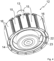
- Fig. 4 shows a perspective view of the rotor 12 with the output shaft 13 and with the carrier body 14, with a lower recess 22 being visible.
- a bearing element 23 is shown as an example, which serves to rotatably accommodate the output shaft 13.
- the carrier body 14 has receiving fields 15 on which the permanent magnets 16 are applied, with three receiving fields 15, for example, no permanent magnet 16 being shown.
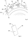
- Fig. 5 shows an enlarged view of the part of the carrier body 14 in the peripheral area of the removed permanent magnets 16 according to Figure 4 ,
- the recording fields 15, which are thus freely visible, are separated from one another by separating webs 19, which form part of the peripheral area 17 of the rotor 12, and the separating webs 19 extend parallel to the Axis of rotation of the rotor, i.e. in its height direction.
- Support strips 20 are formed on the side of the separating webs 19, on which the permanent magnets 16 rest and thus achieve a defined support.
- Trough areas 21 extend between the support strips 20, and if the permanent magnets 16 are arranged on the receiving fields 15, they lie laterally on the support strips 20 and are held by an adhesive which is in the gap thus formed between the permanent magnets 16 and the trough area 21 of the Recording fields 15 is located.
- a defined adhesive gap is achieved via the trough area 21 with a slightly concave curvature, so that an acrylate adhesive, in particular an anaerobic adhesive, can achieve a correspondingly high adhesive performance.
- Fig. 6 finally shows a single view of a permanent magnet 16, and a front surface 34 forms a curved outside which, when glued, points towards the stator, and a rear surface 35 preferably forms a flat surface which points towards the receiving field 15 and with the trough area 21 forms a cavity for the adhesive.
Landscapes
- Engineering & Computer Science (AREA)
- Power Engineering (AREA)
- Manufacturing & Machinery (AREA)
- Power-Operated Mechanisms For Wings (AREA)
- Connection Of Motors, Electrical Generators, Mechanical Devices, And The Like (AREA)
Claims (11)
- Entraînement de porte (100) destiné à être agencé sur ou en relation avec un système de porte, avec lequel au moins un élément battant du système de porte peut être déplacé, présentant une unité moteur (1) comportant un boîtier (10) dans lequel un stator (11) est logé au repos et dans lequel un rotor (12) est agencé de manière rotative dans le boîtier (10), qui présente un arbre de sortie (13), dans lequel l'arbre de sortie (13) peut être placé en liaison fonctionnelle d'entraînement avec l'élément battant, et dans lequel le rotor (12) présente un corps porteur (14) sur lequel sont formés des champs de réception (15) sur lesquels sont collés des aimants permanents (16), dans lequel en outre le rotor (12) présente un zone périphérique (17) qui forme avec les champs de réception (15) une forme polygonale et dans lequel le rotor (12) présente un axe de rotation (18), dans lequel des séparateurs (19) sont formés entre les champs de réception (15), qui font partie de la zone périphérique (17) et s'étendent parallèlement à l'axe de rotation (18), et dans lequel les champs de réception (15) présentent entre les séparateurs (19) une extension longitudinale s'étendant parallèlement à l'axe de rotation (18),
caractérisé, en ce que les champs de réception (15) sont formés sur leur bord longitudinal avec des bandes d'appui (20) latéralement adjacentes aux séparateurs (19), dans lequel les champs de réception (15) présentent une zone de goulotte (21) entre les bandes d'appui (20), de telle sorte que lors de l'agencement des aimants permanents (16) sur les champs de réception (15), un espace d'adhésif défini est formé pour recevoir de l'adhésif. - Entraînement de porte (100) selon la revendication 1, caractérisé, en ce que les aimants permanents (16) dépassent du corps porteur (14) du côté opposé à l'arbre de sortie (13).
- Entraînement de porte (100) selon la revendication 1 ou 2, caractérisé, en ce que le corps porteur (14) présente une forme en T par rapport à sa section transversale périphérique et/ou une forme en H par rapport à sa demi-section, grâce à quoi sont formés côté intérieur des évidements (22) dans lesquels des éléments de palier (23) sont insérés.
- Entraînement de porte (100) selon l'une des revendications précédentes, caractérisé, en ce que l'arbre de sortie (13) est conçu avec une section de logement de rotor (24) sur laquelle est appliqué le corps porteur (14) équipé des aimants permanents (16) et/ou dans lequel l'arbre de sortie (13) présente une première section de palier (25) et une seconde section de palier (26), sur chacune desquelles un élément de palier (23) est reçu, dans lequel la section de réception de rotor (24) est formée entre les sections de palier (25, 26).
- Entraînement de porte (100) selon l'une des revendications précédentes, caractérisé, en ce que le corps porteur (14) est conçu en un matériau métallique fritté ou un matériau moulé.
- Entraînement de porte (100) selon l'une des revendications précédentes, caractérisé, en ce que sur le corps porteur (14) équipé des aimants permanents (16), un corps de maintien en forme de film est appliqué.
- Entraînement de porte (100) selon la revendication 6, caractérisé, en ce que le corps de maintien en forme de film présente un tube isolant en film polyester et peut être rétréci sur le corps porteur (14) équipé des aimants permanents (16).
- Entraînement de porte (100) selon la revendication 6 ou 7, caractérisé, en ce que le corps de support en forme de film est formé d'un corps d'enroulement constitué d'un film de fibres de verre ou d'un tissu de fibres de verre.
- Entraînement de porte (100) selon l'une des revendications précédentes, caractérisé, en ce que l'arbre de sortie (13) s'étend par sections hors d'une face frontale (28) du boîtier (10), de sorte qu'une poulie à courroie (27) est appliquée sur cette section de l'arbre de sortie (1).
- Entraînement de porte (100) selon l'une des revendications précédentes, caractérisé, en ce que l'adhésif pour coller les aimants permanents (16) sur le corps porteur (14) du rotor (12) comprend une colle acrylate et/ou forme une colle anaérobie.
- Système de porte comportant un entraînement de porte (100) selon l'une des revendications précédentes, présentant au moins un élément de liaison destiné à être relié à un élément battant et/ou au moins un élément battant avec lequel l'entraînement de porte (100) est en liaison fonctionnelle d'entraînement.
Priority Applications (6)
| Application Number | Priority Date | Filing Date | Title |
|---|---|---|---|
| EP19214435.0A EP3835531B1 (fr) | 2019-12-09 | 2019-12-09 | Entrainement de porte doté d'une unité moteur d'encombrement réduit haute performance |
| ES19214435T ES2985214T3 (es) | 2019-12-09 | 2019-12-09 | Accionamiento de puerta con una unidad de motor de gran potencia, de pequeño tamaño |
| US17/782,862 US12113399B2 (en) | 2019-12-09 | 2020-12-03 | Door drive with a small high-performance motor unit |
| PCT/EP2020/084535 WO2021115930A1 (fr) | 2019-12-09 | 2020-12-03 | Entraînement de porte doté d'une petite unité moteur haute performance |
| CN202080084428.2A CN114787472B (zh) | 2019-12-09 | 2020-12-03 | 具有功率大的、小构造的马达单元的门驱动器 |
| AU2020403070A AU2020403070B2 (en) | 2019-12-09 | 2020-12-03 | Door drive with a small high-performance motor unit |
Applications Claiming Priority (1)
| Application Number | Priority Date | Filing Date | Title |
|---|---|---|---|
| EP19214435.0A EP3835531B1 (fr) | 2019-12-09 | 2019-12-09 | Entrainement de porte doté d'une unité moteur d'encombrement réduit haute performance |
Publications (3)
| Publication Number | Publication Date |
|---|---|
| EP3835531A1 EP3835531A1 (fr) | 2021-06-16 |
| EP3835531B1 true EP3835531B1 (fr) | 2024-03-27 |
| EP3835531C0 EP3835531C0 (fr) | 2024-03-27 |
Family
ID=68840909
Family Applications (1)
| Application Number | Title | Priority Date | Filing Date |
|---|---|---|---|
| EP19214435.0A Active EP3835531B1 (fr) | 2019-12-09 | 2019-12-09 | Entrainement de porte doté d'une unité moteur d'encombrement réduit haute performance |
Country Status (6)
| Country | Link |
|---|---|
| US (1) | US12113399B2 (fr) |
| EP (1) | EP3835531B1 (fr) |
| CN (1) | CN114787472B (fr) |
| AU (1) | AU2020403070B2 (fr) |
| ES (1) | ES2985214T3 (fr) |
| WO (1) | WO2021115930A1 (fr) |
Families Citing this family (2)
| Publication number | Priority date | Publication date | Assignee | Title |
|---|---|---|---|---|
| EP4485754A1 (fr) * | 2023-06-27 | 2025-01-01 | dormakaba Deutschland GmbH | Dispositif à aimant permanent, machine à flux axial et entraînement électromécanique |
| DE102024134065A1 (de) * | 2024-11-20 | 2026-05-21 | Robert Bosch Gesellschaft mit beschränkter Haftung | Rotor für eine elektronisch kommutierte Elektromaschine und Elektromaschine |
Family Cites Families (15)
| Publication number | Priority date | Publication date | Assignee | Title |
|---|---|---|---|---|
| US4594525A (en) * | 1983-06-27 | 1986-06-10 | General Electric Company | Rotatable assembly for a dynamoelectric machine |
| US5397951A (en) * | 1991-11-29 | 1995-03-14 | Fanuc Ltd. | Rotor for a synchronous rotary machine |
| DE502005010177D1 (de) * | 2005-07-29 | 2010-10-14 | Siemens Ag | Permanentmagnetrotor für eine bürstenlose elektrische Maschine |
| DE202006007139U1 (de) * | 2006-02-10 | 2006-10-26 | Gretsch-Unitas GmbH Baubeschläge | Betätigungsvorrichtung für Türen |
| DE102008046062A1 (de) | 2008-09-08 | 2010-03-11 | Dorma Gmbh + Co. Kg | Nachrüstsatz mit einer Antriebseinheit, insbesondere für eine automatische Schiebetür |
| DE102008047310A1 (de) * | 2008-09-16 | 2010-04-15 | Elau Gmbh | Elektromotor mit sichelförmigen Magnetprofilen |
| JP2010239800A (ja) * | 2009-03-31 | 2010-10-21 | Mitsubishi Electric Corp | 回転電機の回転子およびその製造方法 |
| EP2348612A1 (fr) * | 2010-01-20 | 2011-07-27 | Siemens Aktiengesellschaft | Pièce de composant magnétique pour ensemble de rotor |
| DK2555384T3 (en) * | 2011-08-01 | 2016-10-03 | Siemens Ag | Field structure of an electrical machine |
| JP5958502B2 (ja) * | 2013-12-06 | 2016-08-02 | 株式会社デンソー | 回転子およびそれを用いた回転電機 |
| DE102014115924A1 (de) * | 2014-10-31 | 2016-05-04 | Dorma Deutschland Gmbh | Türantrieb |
| DE102014115932A1 (de) | 2014-10-31 | 2016-05-04 | Dorma Deutschland Gmbh | Türantrieb |
| DE102014115931A1 (de) * | 2014-10-31 | 2016-05-04 | Dorma Deutschland Gmbh | Türantrieb |
| JP6464114B2 (ja) * | 2016-05-20 | 2019-02-06 | ファナック株式会社 | 回転電機の回転子構造および回転電機 |
| CN110212663B (zh) * | 2019-06-19 | 2025-03-28 | 宁波富佳实业股份有限公司 | 外转子无刷电机 |
-
2019
- 2019-12-09 EP EP19214435.0A patent/EP3835531B1/fr active Active
- 2019-12-09 ES ES19214435T patent/ES2985214T3/es active Active
-
2020
- 2020-12-03 CN CN202080084428.2A patent/CN114787472B/zh active Active
- 2020-12-03 WO PCT/EP2020/084535 patent/WO2021115930A1/fr not_active Ceased
- 2020-12-03 US US17/782,862 patent/US12113399B2/en active Active
- 2020-12-03 AU AU2020403070A patent/AU2020403070B2/en active Active
Also Published As
| Publication number | Publication date |
|---|---|
| WO2021115930A1 (fr) | 2021-06-17 |
| CN114787472A (zh) | 2022-07-22 |
| US20230017823A1 (en) | 2023-01-19 |
| US12113399B2 (en) | 2024-10-08 |
| AU2020403070A1 (en) | 2022-06-09 |
| EP3835531A1 (fr) | 2021-06-16 |
| ES2985214T3 (es) | 2024-11-04 |
| CN114787472B (zh) | 2025-08-19 |
| AU2020403070B2 (en) | 2026-03-05 |
| EP3835531C0 (fr) | 2024-03-27 |
Similar Documents
| Publication | Publication Date | Title |
|---|---|---|
| EP2398130B1 (fr) | Petit moteur électrique | |
| EP1657800B1 (fr) | Rotor à aimants permanents | |
| EP2299560B1 (fr) | Procédé d'introduction d'un rotor d'une machine synchrone dans le stator ou pour l'agencement d'un rotor autour d'un stator et son dispositif de montage correspondant | |
| EP2903136A1 (fr) | Tôle de rotor à réluctance dotée d'un évidement pour la réduction de la tension | |
| EP2157328B1 (fr) | Arrangement de coussinet pour une table de machine dotée d'une décharge magnétique | |
| EP3051668B1 (fr) | Segment de rotor et rotor d'une machine électrique | |
| WO2004042891A1 (fr) | Machine a aimant permanent a entrefer axial | |
| DE2037993A1 (de) | Gehäuse fur Motoren von geringer Leistungsfähigkeit, versehen mit von verform ten Flugein festgehaltenen Deckeln | |
| EP2704294A1 (fr) | Rotor d'une machine synchrone à excitation permanente | |
| DE102005042543A1 (de) | Permanenterregte Synchronmaschine | |
| WO2021115930A1 (fr) | Entraînement de porte doté d'une petite unité moteur haute performance | |
| EP3817195A1 (fr) | Rotor pour une machine électrique, procédé de fabrication associé et machine électrique permettant d'entrainer un véhicule | |
| DE202014011226U1 (de) | Elektromotor | |
| DE102011089985B4 (de) | Verfahren zur Herstellung eines Rotors einer Transversalflussmaschine | |
| EP3391511B1 (fr) | Rotor pour une machine synchrone excitee par un aimant permanent, tige d'espace interpolaire pour un tel rotor et procede de fabrication d'un tel rotor | |
| EP1563587B1 (fr) | Dispositif d'entrainement pour dispositifs de reglage de vehicules automobiles | |
| EP3835529B1 (fr) | Entraînement de porte doté d'une unité moteur, comportant un agencement palier avantageux permettant de loger un arbre de sortie | |
| WO2023104229A1 (fr) | Stator pour machine à flux axial | |
| DE102018104074A1 (de) | Rotor, Rotorwelle und elektrische Maschine | |
| EP3835534B1 (fr) | Entrainement de porte doté d'une unité moteur | |
| EP4089284B1 (fr) | Pompe à rotor noyé | |
| EP3835532B1 (fr) | Entrainement de porte doté d'une unité moteur d'une construction simple à densité d'intégration élevée | |
| EP1054758B1 (fr) | Machine de coupe transversale de bandes de materiau | |
| EP1928075A2 (fr) | Moteur électrique sans balais | |
| DE202005005694U1 (de) | Windenergieanlage |
Legal Events
| Date | Code | Title | Description |
|---|---|---|---|
| PUAI | Public reference made under article 153(3) epc to a published international application that has entered the european phase |
Free format text: ORIGINAL CODE: 0009012 |
|
| STAA | Information on the status of an ep patent application or granted ep patent |
Free format text: STATUS: THE APPLICATION HAS BEEN PUBLISHED |
|
| AK | Designated contracting states |
Kind code of ref document: A1 Designated state(s): AL AT BE BG CH CY CZ DE DK EE ES FI FR GB GR HR HU IE IS IT LI LT LU LV MC MK MT NL NO PL PT RO RS SE SI SK SM TR |
|
| STAA | Information on the status of an ep patent application or granted ep patent |
Free format text: STATUS: REQUEST FOR EXAMINATION WAS MADE |
|
| 17P | Request for examination filed |
Effective date: 20211216 |
|
| RBV | Designated contracting states (corrected) |
Designated state(s): AL AT BE BG CH CY CZ DE DK EE ES FI FR GB GR HR HU IE IS IT LI LT LU LV MC MK MT NL NO PL PT RO RS SE SI SK SM TR |
|
| RIC1 | Information provided on ipc code assigned before grant |
Ipc: E05F 15/643 20150101ALN20230831BHEP Ipc: E05F 15/632 20150101ALN20230831BHEP Ipc: H02K 15/03 20060101ALI20230831BHEP Ipc: H02K 1/278 20220101ALI20230831BHEP Ipc: E05F 15/603 20150101AFI20230831BHEP |
|
| RIC1 | Information provided on ipc code assigned before grant |
Ipc: E05F 15/643 20150101ALN20230925BHEP Ipc: E05F 15/632 20150101ALN20230925BHEP Ipc: H02K 15/03 20060101ALI20230925BHEP Ipc: H02K 1/278 20220101ALI20230925BHEP Ipc: E05F 15/603 20150101AFI20230925BHEP |
|
| GRAP | Despatch of communication of intention to grant a patent |
Free format text: ORIGINAL CODE: EPIDOSNIGR1 |
|
| STAA | Information on the status of an ep patent application or granted ep patent |
Free format text: STATUS: GRANT OF PATENT IS INTENDED |
|
| INTG | Intention to grant announced |
Effective date: 20231110 |
|
| GRAS | Grant fee paid |
Free format text: ORIGINAL CODE: EPIDOSNIGR3 |
|
| GRAA | (expected) grant |
Free format text: ORIGINAL CODE: 0009210 |
|
| STAA | Information on the status of an ep patent application or granted ep patent |
Free format text: STATUS: THE PATENT HAS BEEN GRANTED |
|
| AK | Designated contracting states |
Kind code of ref document: B1 Designated state(s): AL AT BE BG CH CY CZ DE DK EE ES FI FR GB GR HR HU IE IS IT LI LT LU LV MC MK MT NL NO PL PT RO RS SE SI SK SM TR |
|
| REG | Reference to a national code |
Ref country code: GB Ref legal event code: FG4D Free format text: NOT ENGLISH |
|
| REG | Reference to a national code |
Ref country code: CH Ref legal event code: EP |
|
| REG | Reference to a national code |
Ref country code: DE Ref legal event code: R096 Ref document number: 502019010885 Country of ref document: DE |
|
| REG | Reference to a national code |
Ref country code: IE Ref legal event code: FG4D Free format text: LANGUAGE OF EP DOCUMENT: GERMAN |
|
| U01 | Request for unitary effect filed |
Effective date: 20240417 |
|
| U07 | Unitary effect registered |
Designated state(s): AT BE BG DE DK EE FI FR IT LT LU LV MT NL PT SE SI Effective date: 20240424 |
|
| PG25 | Lapsed in a contracting state [announced via postgrant information from national office to epo] |
Ref country code: GR Free format text: LAPSE BECAUSE OF FAILURE TO SUBMIT A TRANSLATION OF THE DESCRIPTION OR TO PAY THE FEE WITHIN THE PRESCRIBED TIME-LIMIT Effective date: 20240628 |
|
| PG25 | Lapsed in a contracting state [announced via postgrant information from national office to epo] |
Ref country code: RS Free format text: LAPSE BECAUSE OF FAILURE TO SUBMIT A TRANSLATION OF THE DESCRIPTION OR TO PAY THE FEE WITHIN THE PRESCRIBED TIME-LIMIT Effective date: 20240627 Ref country code: HR Free format text: LAPSE BECAUSE OF FAILURE TO SUBMIT A TRANSLATION OF THE DESCRIPTION OR TO PAY THE FEE WITHIN THE PRESCRIBED TIME-LIMIT Effective date: 20240327 |
|
| PG25 | Lapsed in a contracting state [announced via postgrant information from national office to epo] |
Ref country code: RS Free format text: LAPSE BECAUSE OF FAILURE TO SUBMIT A TRANSLATION OF THE DESCRIPTION OR TO PAY THE FEE WITHIN THE PRESCRIBED TIME-LIMIT Effective date: 20240627 Ref country code: NO Free format text: LAPSE BECAUSE OF FAILURE TO SUBMIT A TRANSLATION OF THE DESCRIPTION OR TO PAY THE FEE WITHIN THE PRESCRIBED TIME-LIMIT Effective date: 20240627 Ref country code: HR Free format text: LAPSE BECAUSE OF FAILURE TO SUBMIT A TRANSLATION OF THE DESCRIPTION OR TO PAY THE FEE WITHIN THE PRESCRIBED TIME-LIMIT Effective date: 20240327 Ref country code: GR Free format text: LAPSE BECAUSE OF FAILURE TO SUBMIT A TRANSLATION OF THE DESCRIPTION OR TO PAY THE FEE WITHIN THE PRESCRIBED TIME-LIMIT Effective date: 20240628 |
|
| PG25 | Lapsed in a contracting state [announced via postgrant information from national office to epo] |
Ref country code: IS Free format text: LAPSE BECAUSE OF FAILURE TO SUBMIT A TRANSLATION OF THE DESCRIPTION OR TO PAY THE FEE WITHIN THE PRESCRIBED TIME-LIMIT Effective date: 20240727 |
|
| PG25 | Lapsed in a contracting state [announced via postgrant information from national office to epo] |
Ref country code: SM Free format text: LAPSE BECAUSE OF FAILURE TO SUBMIT A TRANSLATION OF THE DESCRIPTION OR TO PAY THE FEE WITHIN THE PRESCRIBED TIME-LIMIT Effective date: 20240327 |
|
| PG25 | Lapsed in a contracting state [announced via postgrant information from national office to epo] |
Ref country code: CZ Free format text: LAPSE BECAUSE OF FAILURE TO SUBMIT A TRANSLATION OF THE DESCRIPTION OR TO PAY THE FEE WITHIN THE PRESCRIBED TIME-LIMIT Effective date: 20240327 |
|
| PG25 | Lapsed in a contracting state [announced via postgrant information from national office to epo] |
Ref country code: PL Free format text: LAPSE BECAUSE OF FAILURE TO SUBMIT A TRANSLATION OF THE DESCRIPTION OR TO PAY THE FEE WITHIN THE PRESCRIBED TIME-LIMIT Effective date: 20240327 |
|
| PG25 | Lapsed in a contracting state [announced via postgrant information from national office to epo] |
Ref country code: SK Free format text: LAPSE BECAUSE OF FAILURE TO SUBMIT A TRANSLATION OF THE DESCRIPTION OR TO PAY THE FEE WITHIN THE PRESCRIBED TIME-LIMIT Effective date: 20240327 |
|
| PG25 | Lapsed in a contracting state [announced via postgrant information from national office to epo] |
Ref country code: SM Free format text: LAPSE BECAUSE OF FAILURE TO SUBMIT A TRANSLATION OF THE DESCRIPTION OR TO PAY THE FEE WITHIN THE PRESCRIBED TIME-LIMIT Effective date: 20240327 Ref country code: SK Free format text: LAPSE BECAUSE OF FAILURE TO SUBMIT A TRANSLATION OF THE DESCRIPTION OR TO PAY THE FEE WITHIN THE PRESCRIBED TIME-LIMIT Effective date: 20240327 Ref country code: RO Free format text: LAPSE BECAUSE OF FAILURE TO SUBMIT A TRANSLATION OF THE DESCRIPTION OR TO PAY THE FEE WITHIN THE PRESCRIBED TIME-LIMIT Effective date: 20240327 Ref country code: PL Free format text: LAPSE BECAUSE OF FAILURE TO SUBMIT A TRANSLATION OF THE DESCRIPTION OR TO PAY THE FEE WITHIN THE PRESCRIBED TIME-LIMIT Effective date: 20240327 Ref country code: IS Free format text: LAPSE BECAUSE OF FAILURE TO SUBMIT A TRANSLATION OF THE DESCRIPTION OR TO PAY THE FEE WITHIN THE PRESCRIBED TIME-LIMIT Effective date: 20240727 Ref country code: CZ Free format text: LAPSE BECAUSE OF FAILURE TO SUBMIT A TRANSLATION OF THE DESCRIPTION OR TO PAY THE FEE WITHIN THE PRESCRIBED TIME-LIMIT Effective date: 20240327 |
|
| REG | Reference to a national code |
Ref country code: ES Ref legal event code: FG2A Ref document number: 2985214 Country of ref document: ES Kind code of ref document: T3 Effective date: 20241104 |
|
| REG | Reference to a national code |
Ref country code: DE Ref legal event code: R097 Ref document number: 502019010885 Country of ref document: DE |
|
| U20 | Renewal fee for the european patent with unitary effect paid |
Year of fee payment: 6 Effective date: 20241227 |
|
| PLBE | No opposition filed within time limit |
Free format text: ORIGINAL CODE: 0009261 |
|
| STAA | Information on the status of an ep patent application or granted ep patent |
Free format text: STATUS: NO OPPOSITION FILED WITHIN TIME LIMIT |
|
| 26N | No opposition filed |
Effective date: 20250103 |
|
| PG25 | Lapsed in a contracting state [announced via postgrant information from national office to epo] |
Ref country code: MC Free format text: LAPSE BECAUSE OF FAILURE TO SUBMIT A TRANSLATION OF THE DESCRIPTION OR TO PAY THE FEE WITHIN THE PRESCRIBED TIME-LIMIT Effective date: 20240327 |
|
| PG25 | Lapsed in a contracting state [announced via postgrant information from national office to epo] |
Ref country code: IE Free format text: LAPSE BECAUSE OF NON-PAYMENT OF DUE FEES Effective date: 20241209 |
|
| REG | Reference to a national code |
Ref country code: CH Ref legal event code: U11 Free format text: ST27 STATUS EVENT CODE: U-0-0-U10-U11 (AS PROVIDED BY THE NATIONAL OFFICE) Effective date: 20260101 |
|
| PGFP | Annual fee paid to national office [announced via postgrant information from national office to epo] |
Ref country code: GB Payment date: 20251219 Year of fee payment: 7 |
|
| U20 | Renewal fee for the european patent with unitary effect paid |
Year of fee payment: 7 Effective date: 20251230 |
|
| PGFP | Annual fee paid to national office [announced via postgrant information from national office to epo] |
Ref country code: ES Payment date: 20260130 Year of fee payment: 7 |
|
| PGFP | Annual fee paid to national office [announced via postgrant information from national office to epo] |
Ref country code: CH Payment date: 20260101 Year of fee payment: 7 |