EP2397714A2 - Wellenkupplung - Google Patents
Wellenkupplung Download PDFInfo
- Publication number
- EP2397714A2 EP2397714A2 EP20110004280 EP11004280A EP2397714A2 EP 2397714 A2 EP2397714 A2 EP 2397714A2 EP 20110004280 EP20110004280 EP 20110004280 EP 11004280 A EP11004280 A EP 11004280A EP 2397714 A2 EP2397714 A2 EP 2397714A2
- Authority
- EP
- European Patent Office
- Prior art keywords
- shaft
- coupling
- coupling sleeve
- toothing
- teeth
- Prior art date
- Legal status (The legal status is an assumption and is not a legal conclusion. Google has not performed a legal analysis and makes no representation as to the accuracy of the status listed.)
- Granted
Links
- 230000008878 coupling Effects 0.000 title claims description 50
- 238000010168 coupling process Methods 0.000 title claims description 50
- 238000005859 coupling reaction Methods 0.000 title claims description 50
- 230000015572 biosynthetic process Effects 0.000 claims abstract 2
- 238000007373 indentation Methods 0.000 claims 1
- 229910000831 Steel Inorganic materials 0.000 abstract description 9
- 239000010959 steel Substances 0.000 abstract description 9
- 239000000463 material Substances 0.000 description 7
- 230000005540 biological transmission Effects 0.000 description 4
- 229910001018 Cast iron Inorganic materials 0.000 description 2
- 238000005266 casting Methods 0.000 description 2
- 238000004519 manufacturing process Methods 0.000 description 2
- 230000003313 weakening effect Effects 0.000 description 2
- 229910001060 Gray iron Inorganic materials 0.000 description 1
- 238000004364 calculation method Methods 0.000 description 1
- 238000010276 construction Methods 0.000 description 1
- 239000013013 elastic material Substances 0.000 description 1
- 230000008092 positive effect Effects 0.000 description 1
- 230000003068 static effect Effects 0.000 description 1
- 239000000725 suspension Substances 0.000 description 1
Images

Classifications
-
- F—MECHANICAL ENGINEERING; LIGHTING; HEATING; WEAPONS; BLASTING
- F16—ENGINEERING ELEMENTS AND UNITS; GENERAL MEASURES FOR PRODUCING AND MAINTAINING EFFECTIVE FUNCTIONING OF MACHINES OR INSTALLATIONS; THERMAL INSULATION IN GENERAL
- F16D—COUPLINGS FOR TRANSMITTING ROTATION; CLUTCHES; BRAKES
- F16D1/00—Couplings for rigidly connecting two coaxial shafts or other movable machine elements
- F16D1/02—Couplings for rigidly connecting two coaxial shafts or other movable machine elements for connecting two abutting shafts or the like
-
- F—MECHANICAL ENGINEERING; LIGHTING; HEATING; WEAPONS; BLASTING
- F16—ENGINEERING ELEMENTS AND UNITS; GENERAL MEASURES FOR PRODUCING AND MAINTAINING EFFECTIVE FUNCTIONING OF MACHINES OR INSTALLATIONS; THERMAL INSULATION IN GENERAL
- F16D—COUPLINGS FOR TRANSMITTING ROTATION; CLUTCHES; BRAKES
- F16D1/00—Couplings for rigidly connecting two coaxial shafts or other movable machine elements
- F16D1/10—Quick-acting couplings in which the parts are connected by simply bringing them together axially
-
- F—MECHANICAL ENGINEERING; LIGHTING; HEATING; WEAPONS; BLASTING
- F16—ENGINEERING ELEMENTS AND UNITS; GENERAL MEASURES FOR PRODUCING AND MAINTAINING EFFECTIVE FUNCTIONING OF MACHINES OR INSTALLATIONS; THERMAL INSULATION IN GENERAL
- F16D—COUPLINGS FOR TRANSMITTING ROTATION; CLUTCHES; BRAKES
- F16D3/00—Yielding couplings, i.e. with means permitting movement between the connected parts during the drive
- F16D3/16—Universal joints in which flexibility is produced by means of pivots or sliding or rolling connecting parts
- F16D3/18—Universal joints in which flexibility is produced by means of pivots or sliding or rolling connecting parts the coupling parts (1) having slidably-interengaging teeth
- F16D3/185—Universal joints in which flexibility is produced by means of pivots or sliding or rolling connecting parts the coupling parts (1) having slidably-interengaging teeth radial teeth connecting concentric inner and outer coupling parts
-
- F—MECHANICAL ENGINEERING; LIGHTING; HEATING; WEAPONS; BLASTING
- F16—ENGINEERING ELEMENTS AND UNITS; GENERAL MEASURES FOR PRODUCING AND MAINTAINING EFFECTIVE FUNCTIONING OF MACHINES OR INSTALLATIONS; THERMAL INSULATION IN GENERAL
- F16D—COUPLINGS FOR TRANSMITTING ROTATION; CLUTCHES; BRAKES
- F16D1/00—Couplings for rigidly connecting two coaxial shafts or other movable machine elements
- F16D1/06—Couplings for rigidly connecting two coaxial shafts or other movable machine elements for attachment of a member on a shaft or on a shaft-end
- F16D2001/062—Couplings for rigidly connecting two coaxial shafts or other movable machine elements for attachment of a member on a shaft or on a shaft-end characterised by adaptors where hub bores being larger than the shaft
-
- F—MECHANICAL ENGINEERING; LIGHTING; HEATING; WEAPONS; BLASTING
- F16—ENGINEERING ELEMENTS AND UNITS; GENERAL MEASURES FOR PRODUCING AND MAINTAINING EFFECTIVE FUNCTIONING OF MACHINES OR INSTALLATIONS; THERMAL INSULATION IN GENERAL
- F16D—COUPLINGS FOR TRANSMITTING ROTATION; CLUTCHES; BRAKES
- F16D1/00—Couplings for rigidly connecting two coaxial shafts or other movable machine elements
- F16D1/10—Quick-acting couplings in which the parts are connected by simply bringing them together axially
- F16D2001/103—Quick-acting couplings in which the parts are connected by simply bringing them together axially the torque is transmitted via splined connections
Definitions
- the invention relates to a coupling for two torque-wise interconnected shafts with a arranged between the ends of the shafts coupling sleeve.
- Object of the present invention is therefore to make the coupling very compact and space-saving.
- This object is achieved in that the ends of the two torque-wise connected to each other waves overlap to form an annular gap and the coupling sleeve is arranged in the annular gap.
- the invention has the advantage that no separate space must be provided for the coupling sleeve in the axial direction, so that a transmission with a corresponding coupling is very short executable.
- a corresponding gear housing is shorter and thus particularly weight-saving executable.
- the coupling sleeve has at its one end an inner and at its other end an external toothing, which cooperate with corresponding toothings on the shaft ends.
- Such gears are known to be very reliable and the production of such teeth is not a problem for a gear-producing operation.
- At least one of the teeth is provided on a toothed ring connected to the corresponding shaft end.
- Veriereungskranz can also consist of steel as the coupling sleeve.
- the particularly wear-prone joint toothing is a combination of steel / steel, which is very wear-resistant.
- the existing steel separate gear ring can then be pressed, for example, firmly in him receiving hollow shaft shaft end.
- press seats are again subject to special limitations, it is proposed, in particular, to connect the toothed ring in a rotationally fixed manner by means of a toothed seat with the shaft end receiving it.
- the coupling sleeve is fixed at its axial ends via bearing flanges respectively connected to the shaft ends in the axial direction.
- the end 1 of a shaft 2 This is to be connected torque-wise to the end 3 of a (not shown) second shaft.
- the end 1 of the shaft 2 is provided with a terminal external toothing 4.
- the end 3 of the second (not shown) shaft is hollow shaft-like and is provided at the end with an internal toothing 5.
- the hollow shaft-like end 3 engages over the end 1 of the shaft 2, so that there is an annular gap 6 therebetween.
- a coupling sleeve is arranged, which has at its one axial end an internal toothing 8, as well as at its opposite end in the axial direction of an external toothing.
- the internal toothing 8 of the coupling sleeve 7 corresponds to the external toothing 4 of the shaft 1 and the external toothing 9 of the coupling sleeve 7 corresponds to the internal toothing 5 of the hollow-shaft-like end 3 of the second (not shown) shaft.
- the external teeth of the corresponding pairings are crowned, so that over the coupling sleeve 7, an angular and / or radial offset can be compensated.
- the hollow shaft-like shaft end 3 may consist of a wear-prone material such as gray cast iron, therefore, the internal teeth 5, which meshes with the external teeth 9 of the coupling sleeve 7, not directly on the shaft end 3 but at one with the Shaft end 3 connected toothed ring 10.
- This toothed ring 10 is made of steel, so that between him and the coupling sleeve 7 is a combination of materials steel / steel, which is relatively resistant to wear.
- the toothed ring 10 is externally provided with a toothing 11 so that it is rotatably connected via a splined seat with the shaft end 3.
- abutment flanges 12, 13 are fastened correspondingly to the shaft ends 1 and 3, respectively, and make it possible to guide the forces occurring within the toothings between the shaft ends and the coupling sleeve and possibly also to short them.
- the coupling sleeve 7 is toroidal at its axial ends 14, 15.
- this toothed ring 10 is used in a rotationally fixed manner in the shaft end 3 via its toothed seat 11.
- a corresponding toothing 5 is therefore corrected during its manufacture. At a specific predetermined torque so that a corresponding deformation and congestion can be avoided.
- the toothing 5 on the toothed ring 10 is engaged on one side in the axial direction by a U-shaped notch 18.
- This incision 18 forms an intended weakening of the material below the toothing so that, given a torque load, the end region 16 of the toothing 5 defines yields and thus the tooth ends of the toothing 5 are correspondingly relieved at any desired load. - Thus, a corresponding toothing wear is more resistant.
Landscapes
- Engineering & Computer Science (AREA)
- General Engineering & Computer Science (AREA)
- Mechanical Engineering (AREA)
- Mechanical Operated Clutches (AREA)
- Gears, Cams (AREA)
Abstract
Description
- Die Erfindung betrifft eine Kupplung für zwei drehmomentmäßig miteinander zu verbindende Wellen mit einer zwischen den Enden der Wellen angeordneten Kupplungshülse.
- Zum Ausgleich von radialem und/oder winkligem Versatz von Wellen, die drehmomentmäßig verbunden werden sollen, werden oft Doppelgelenkkupplungen verwendet. Es ist dabei bekannt, die sich gegenüberliegenden Wellenenden mit Außenverzahnungen zu versehen und die die beiden Wellenenden verbindende Kuppelungshülse dann mit korrespondierenden Innenverzahnungen. Die Kupplungshülse wird dann auf den beiden sich gegenüberliegenden Wellenenden jeweils spielbehaftet axial fixiert, wobei zum Ausgleich der genannten Fluchtungsabweichungen üblicherweise die auf den Wellenenden vorhandenen Außenverzahnungen zweidimensional ballig ausgeführt werden.
- Es ist bei anderen Anwendungsfällen auch bekannt, wenigstens eine der Wellen als Hohlwelle auszuführen und dann die Kupplungshülse in diese Hohlwelle hineinlaufen zu lassen. Dabei ist dann das Hohlwellenende mit einer Innenverzahnung versehen und die Kupplungshülse trägt an dieser Stelle eine korrespondierende Außenverzahnung. Auch bei diesen Anwendungsfällen sind die genannten Außenverzahnungen zum Ausgleich der Fluchtungsabweichungen ballig ausgeführt.
- In den beschriebenen Kupplungen können erhebliche Axialkräfte entstehen, die u. a. abhängen vom Antriebsdrehmoment, vom Teilkreisdurchmesser der vorgesehenen Verzahnungen und/oder vom Reibbeiwert innerhalb der Verzahnung.
- Die diesbezüglich zur Anwendung kommenden Berechnungsverfahren zeigen in der Praxis gewisse Einschränkungen. So ist es nicht nachgewiesen, ob die Kräfte tatsächlich nur in ihrer errechneten maximalen Höhe auftreten. Auch musste festgestellt werden, dass die in den einzelnen Verzahnungen sich ergebenden Kräfte sich selbst bei einer symmetrischen Kupplungsgestaltung nicht gegenseitig aufheben. Vielmehr sind Fälle bekannt, in denen sich die Kräfte zu einander addieren.
- Dies bedeutet aber, dass die Wellenlagerungen nicht nur durch die bekannten und gut berechenbaren Betriebslasten beansprucht werden, sondern dass durch die ggf. vorgesehene Kupplung noch erheblich höhere Lasten auftreten können. Demgemäß müssen die Wellenlagerungen konstruktiv größer ausgeführt werden, was eine entsprechende Verteuerung der entsprechenden Getriebe mit sich bringt.
- Außerdem muss für die Kupplungshülse ein zusätzlicher Bauraum vorgesehen werden. Ein entsprechend ausgerüstetes Getriebe baut unter diesem Aspekt somit entsprechend länger. Demgemäß ist für dieses Getriebe also auch ein entsprechend größeres Gehäuse vorzusehen, das natürlich auch entsprechend schwerer ist.
- Hierdurch können sich bei besonderen Anwendungsfällen erhebliche Folgen ergeben: So ist ein spezielles Anwendungsbeispiel für eine erfindungsgemäße Kupplung der Anschluss eines Planetengetriebes in einer Windkraftanlage. Ein solches Getriebe hat Dimensionen, bei denen ein Gehäuse einen Durchmesser von ca. 3 m und mehr haben kann. Aufgrund der für die Kupplung vorzusehenden Gehäuseverlängerung resultiert hieraus ein zusätzliches Gewicht, das mehrere Tonnen betragen kann. Dies erschwert einerseits die Montage des Getriebes bei der Errichtung der Windkraftanlage und erhöht andererseits auch die dauernde statische Belastung des Mastes, an dem der Rotor sowie das mit diesem zusammengekoppelte Getriebe und der nachgeschaltete Generator aufgehängt werden. Aufgrund dieses erhöhten, zusätzlichen Gewichtes müssen dabei auch die das Getriebe und den Generator aufnehmende Gondel sowie die Aufhängung für diese stabiler und damit schwerer ausgeführt werden, was die Belastung z. B. für den Mast weiter verschärft.
- Aufgabe der vorliegenden Erfindung ist es daher, die Kupplung besonders kompakt und raumsparend zu gestalten.
- Diese Aufgabe wird erfindungsgemäß dadurch gelöst, dass die Enden der zwei drehmomentmäßig miteinander zu verbindenden Wellen sich unter Bildung eines Ringspaltes übergreifen und die Kupplungshülse in dem Ringspalt angeordnet ist.
- Die Erfindung hat den Vorteil, dass für die Kupplungshülse in Axialrichtung kein separater Bauraum vorgesehen werden muss, so dass ein Getriebe mit einer entsprechenden Kupplung sehr kurz ausführbar ist. Damit ist auch ein entsprechendes Getriebegehäuse kürzer und damit insbesondere gewichtssparend ausführbar.
- Bei einer besonders bevorzugten Ausführungsform hat die Kupplungshülse an ihrem einen Ende eine Innen- und an ihrem anderen Ende eine Außenverzahnung, die mit korrespondierenden Verzahnungen an den Wellenenden zusammenwirken.
- Derartige Verzahnungen sind bekanntermaßen sehr betriebssicher und die Herstellung derartiger Verzahnungen stellt für einen getriebeherstellenden Betrieb keine Probleme dar.
- Es wird vorgeschlagen, dass wenigstens eine der Verzahnungen an einem mit dem entsprechenden Wellenende verbundenen Verzahnungskranz vorgesehen ist.
- Hiermit ist insbesondere das Problem zu lösen, dass die o. g. Innen- bzw. Außenverzahnungen der Kupplungshülse und/oder oder die korrespondierenden Verzahnungen an den Wellenenden einem besonderen Verschleiß unterliegen: Wird beispielsweise eine der Wellen, deren Wellenenden drehmomentmäßig mit der anderen Welle verbunden werden soll, aus hier nicht näher diskutierten Gründen als Gussteil hergestellt, z. B. aus Grauguss, so hat diese einen erheblich geringeren Verschleißwiderstand als insbesondere die Kupplungshülse, die üblicherweise aus Stahl hergestellt wird. Um dies auszugleichen, müsste eigentlich die Verzahnung entsprechend vergrößert werden, was aber eine unerwünschte Vergrößerung des benötigten Bauraums zur Folge hätte und damit die wiederum oben bereits beschriebenen negativen Rückwirkungen auf die Größe, das Gewicht und die Kosten des Gehäuses.
- Der jetzt vorgesehene Verzahnungskranz kann dabei ebenfalls aus Stahl bestehen wie die Kupplungshülse. Damit ist die besonders verschleißgefährdete Gelenkverzahnung eine Kombination Stahl/Stahl, die sehr verschleißfest ist.
- Der aus Stahl bestehende separate Verzahnungskranz kann dann beispielsweise fest in das ihn aufnehmende hohlwellenartige Wellenende eingepresst werden.
- Da Presssitze aber wieder speziellen Begrenzungen unterliegen, wird insbesondere vorgeschlagen, den Verzahnungskranz mittels eines Verzahnungssitzes mit dem ihn aufnehmenden Wellenende drehfest zu verbinden.
- Insbesondere wird auf diese Weise verhindert, dass an dem eigentlichen Wellenmaterial, dass wie oben beschrieben das relativ empfindliche Gussmaterial sein kann, ein Verschleiß aufgrund von Relativbewegungen auftreten kann.
- Um den Verschleiß der Kupplungshülse weiter zu verringern, wird des Weiteren vorgeschlagen, diese an ihren axialen Enden torusförmig auszubilden. Hierdurch wird erreicht, dass die axialen Anlagen der Kupplungshülse eine Winkelbewegung der zu verbindenden Wellen ermöglichen durch ein Wälz-Gleiten unter Axiallast, das sehr verlustarm erfolgen kann. Die miteinander zu verbindenden Wellen können somit leicht gegeneinander bewegt werden.
- Insbesondere ist die Kupplungshülse an ihren axialen Enden über mit den Wellenenden jeweils verbundene Anlageflansche in Axialrichtung fixiert.
- Dies hat insbesondere den Vorteil, dass die innerhalb der Kupplung durch die Gelenkreibung entstehenden axialen Kräfte sich auf unterschiedlichste Weise, je nach Richtung der Axialkraft, kurzschließen können. Damit wird eine Entlastung der Wellenlager erreicht und diese können damit kleiner ausgelegt werden, was unter den oben diskutierten Aspekten positive Auswirkungen bezüglich einer kleineren Dimensionierung auch des Getriebegehäuses etc. mit sich bringt.
- Bei der Auslegung der Verzahnungen innerhalb der Kupplung ist es bekannt, dass sich diese insbesondere bei einem relativ elastischen Material wie beispielsweise Grauguss entsprechend dem Drehmomentaufbau verdrillt und somit die Endkanten der die Verzahnung bildenden Zähne insbesondere im Gussmaterial leicht überlastet werden können.
- Um dies zu kompensieren wird klassischerweise eine oder beide der miteinander korrespondierenden Verzahnungen bei der Bearbeitung korrigiert. Dies ist allerdings nur für ein betragsmäßig bestimmtes Drehmoment exakt ausführbar.
- Für eine besonders bevorzugte Ausführungsform wird daher vorgeschlagen, eine U-förmig ausgeprägte bewusste Materialschwächung unter der Verzahnung des Verzahnungskranzes vorzusehen.
- Hierdurch wird erreicht, dass der Endbereich der Verzahnung des Verzahnungskranzes drehmomentabhängig nachgibt und somit die Zahnenden bei den unterschiedlichsten Belastungen bedarfsgerecht entlastet werden.
- Weitere Vorteile und Merkmale der Erfindung ergeben sich aus der nachfolgenden Beschreibung eines Ausführungsbeispiels.
- Dabei zeigt:
- Figur 1
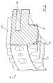
- Schnitt durch eine Doppelgelenkkupplung;
- Figur 2
- Schnitt durch einen Verzahnungskranz.
- In der
Figur 1 erkennt man das Ende 1 einer Welle 2. Dieses ist mit dem Ende 3 einer (nicht näher dargestellten) zweiten Welle drehmomentmäßig zu verbinden. Hierzu ist das Ende 1 der Welle 2 mit einer endständigen Außenverzahnung 4 versehen. Außerdem ist das Ende 3 der zweiten (nicht näher dargestellten) Welle hohlwellenartig ausgeführt und ist endständig mit einer Innenverzahnung 5 versehen. - Das hohlwellenartige Ende 3 übergreift das Ende 1 der Welle 2, so dass sich dazwischen ein Ringspalt 6 ergibt.
- In diesem Ringspalt 6 ist eine Kupplungshülse angeordnet, die an ihrem einen axialen Ende eine Innenverzahnung 8 aufweist, sowie an ihrem in Axialrichtung gegenüberliegenden anderen Ende eine Außenverzahnung 9.
- Die Innenverzahnung 8 der Kupplungshülse 7 korrespondiert mit der Außenverzahnung 4 der Welle 1 und die Außenverzahnung 9 der Kupplungshülse 7 korrespondiert mit der Innenverzahnung 5 des hohlwellenartigen Endes 3 der zweiten (nicht näher dargestellten) Welle.
- Jeweils die Außenverzahnungen der entsprechenden Paarungen sind ballig ausgeführt, so dass über die Kupplungshülse 7 ein winkliger und/oder radialer Versatz ausgeglichen werden kann.
- Dabei kommt es zu Relativbewegungen innerhalb der Verzahnung. Bei einem wie hier dargestellten Beispiel, bei dem das hohlwellenartigen Wellenende 3 aus einem verschleißanfälligen Material wie beispielsweise Grauguss bestehen kann, befindet sich deshalb die Innenverzahnung 5, die mit der Außenverzahnung 9 der Kupplungshülse 7 kämmt, nicht unmittelbar am Wellenende 3 sondern an einem mit dem Wellenende 3 verbundenen Verzahnungskranz 10. Dieser Verzahnungskranz 10 ist aus Stahl, so dass zwischen ihm und der Kupplungshülse 7 eine Materialkombination Stahl/Stahl vorliegt, die relativ verschleißfest ist.
- Um die von der Kupplungshülse 7 kommenden Drehmomente vom Verzahnungskranz 10 in das hohlwellenartige Wellenende 3 einzuleiten, ist der Verzahnungskranz 10 außen mit einer Verzahnung 11 versehen, so dass er über einem Verzahnungssitz drehfest mit dem Wellenende 3 verbunden ist.
- Um die Kupplungshülse 7 in ihrer axialen Position zu fixieren, ist sie über scheibenartige Anlageflansche 12, 13 gehalten. Diese Anlageflansche 12, 13 sind entsprechend an den Wellenenden 1 bzw. 3 befestigt und ermöglichen, die innerhalb der Verzahnungen auftretenden Kräfte zwischen der Wellenenden und der Kupplungshülse entstehend zu führen und ggf. auch kurzzuschließen.
- Um die bei der Verdrehung der Wellenenden auftretende winkelige Bewegung zwischen den Anlageflanschen 12, 13 und der Kupplungshülse 7 zu ermöglichen, ist die Kupplungshülse 7 an ihren axialen Enden 14, 15 torusförmig ausgebildet.
- In der
Figur 2 erkennt man den Verzahnungskranz 10 in einer perspektivischen, geschnittenen Ansicht. - Dieser Verzahnungskranz 10 wird wie gesagt über seinen Verzahnungssitz 11 verdrehfest in das Wellenende 3 eingesetzt.
- Es ist jetzt bekannt, dass bei Einleitung von Drehmomenten in die Innenverzahnung 5 diese sich entsprechend dem Drehmomentaufbau verdrillt und somit Endkanten 16, 17 zu einer Überlastung neigen.
- Klassischerweise wird eine entsprechende Verzahnung 5 deswegen bei ihrer Herstellung korrigiert. Bei einem speziellen vorgegebenen Drehmoment kann damit eine entsprechende Verformung und damit Überlastung vermieden werden.
- Bei der hier dargestellten Ausführungsform ist an dem Verzahnungskranz 10 aber die Verzahnung 5 einseitig in Axialrichtung durch einen U-förmigen Einschnitt 18 untergriffen. Dieser Einschnitt 18 bildet eine beabsichtigte Materialschwächung unterhalb der Verzahnung, so dass bei einer drehmomentmäßigen Belastung der Endbereich 16 der Verzahnung 5 definiert nachgibt und somit die Zahnenden der Verzahnung 5 bei jeder beliebigen Belastung korrespondierend entlastet werden. - Damit ist eine entsprechende Verzahnung verschleißfester.
Claims (7)
- Kupplung für zwei dremomentmäßig miteinander zu verbindende Wellen mit einer zwischen den Enden (1, 3) der Wellen angeordneten Kupplungshülse (7),
dadurch gekennzeichnet,
dass die Enden (1, 3) der Wellen sich unter Bildung eines Ringspaltes (6) übergreifen und die Kupplungshülse (7) in dem Ringspalt (6) angeordnet ist. - Kupplung gemäß Anspruch 1,
dadurch gekennzeichnet,
dass die Kupplungshülse (7) an ihrem einen axialen Ende eine Innenverzahnung (8) und an ihrem anderen axialen Ende eine Außenverzahnung (9) aufweist, die mit korrespondierenden Verzahnungen (4, 5) an den Wellenenden (1, 3) zusammenwirken. - Kupplung gemäß Anspruch 2,
dadurch gekennzeichnet,
dass wenigstens eine der korrespondierenden Verzahnungen (4, 5) an einem mit dem entsprechenden Wellende (3) verbundenen Verzahnungskranz (10) vorgesehen ist. - Kupplung gemäß Anspruch 3,
dadurch gekennzeichnet,
dass der Verzahnungskranz (10) mittels eines Verzahnungssitzes (11) mit dem entsprechenden Wellenende (3) drehfest verbunden ist. - Kupplung gemäß einem oder mehreren der vorhergehenden Ansprüche,
dadurch gekennzeichnet,
dass die Kupplungshülse (7) an ihren axialen Enden (14, 15) torusförmig ausgebildet ist. - Kupplung gemäß einem oder mehreren der vorhergehenden Ansprüche,
dadurch gekennzeichnet,
dass die Kupplungshülse (7) an ihren axialen Enden (14, 15) über mit den Wellenenden (1, 3) verbundenen Anlageflanschen (12, 13) fixiert ist. - Kupplung gemäß einem oder mehreren der vorhergehenden Ansprüche,
dadurch gekennzeichnet,
dass der Verzahnungskranz (10) mit einem die Verzahnung (5) einseitig in Axialrichtung untergreifenden Einschnitt (18) versehen ist.
Applications Claiming Priority (1)
| Application Number | Priority Date | Filing Date | Title |
|---|---|---|---|
| DE201010023780 DE102010023780A1 (de) | 2010-06-15 | 2010-06-15 | Doppelgelenkkupplung |
Publications (3)
| Publication Number | Publication Date |
|---|---|
| EP2397714A2 true EP2397714A2 (de) | 2011-12-21 |
| EP2397714A3 EP2397714A3 (de) | 2013-10-16 |
| EP2397714B1 EP2397714B1 (de) | 2015-11-04 |
Family
ID=44650550
Family Applications (1)
| Application Number | Title | Priority Date | Filing Date |
|---|---|---|---|
| EP11004280.1A Not-in-force EP2397714B1 (de) | 2010-06-15 | 2011-05-24 | Wellenkupplung |
Country Status (3)
| Country | Link |
|---|---|
| EP (1) | EP2397714B1 (de) |
| DE (1) | DE102010023780A1 (de) |
| ES (1) | ES2554860T3 (de) |
Family Cites Families (9)
| Publication number | Priority date | Publication date | Assignee | Title |
|---|---|---|---|---|
| GB1514345A (en) * | 1975-10-23 | 1978-06-14 | Allen Sons & Co Ltd W | Gear coupling |
| DE3822637A1 (de) * | 1988-07-05 | 1990-01-18 | Daimler Benz Ag | Elastische verdrehsichere wellen-nabenverbindung |
| CA2159158C (en) * | 1994-09-27 | 1999-01-26 | Masaki Tsunoda | System for outputting power from a crankshaft |
| US5993186A (en) * | 1997-08-29 | 1999-11-30 | General Electric Company | Single screw extruder |
| IT245258Y1 (it) * | 1998-10-02 | 2002-03-20 | Annovi E Reverberi S R L | Sistema per l'accoppiamento diretto di due alberi rotanti coassiali, e relativo dispositivo. |
| DE29822647U1 (de) * | 1998-12-22 | 1999-06-10 | IWD Ingenieur Werner Dill GmbH & Co.KG, 61462 Königstein | Hohlwelle mit Kupplungsbüchse |
| JP4256849B2 (ja) * | 2004-05-31 | 2009-04-22 | ゲイツ・ユニッタ・アジア株式会社 | カップリング |
| US20060046858A1 (en) * | 2004-08-26 | 2006-03-02 | Ronald Brissette | Driveshaft assembly with torque ring coupling |
| DE102007018464A1 (de) * | 2007-04-19 | 2008-10-23 | Robert Bosch Gmbh | Motorisch angetriebene Werkzeugmaschine |
-
2010
- 2010-06-15 DE DE201010023780 patent/DE102010023780A1/de not_active Withdrawn
-
2011
- 2011-05-24 EP EP11004280.1A patent/EP2397714B1/de not_active Not-in-force
- 2011-05-24 ES ES11004280.1T patent/ES2554860T3/es active Active
Non-Patent Citations (1)
| Title |
|---|
| None |
Also Published As
| Publication number | Publication date |
|---|---|
| DE102010023780A1 (de) | 2011-12-15 |
| EP2397714B1 (de) | 2015-11-04 |
| ES2554860T3 (es) | 2015-12-23 |
| EP2397714A3 (de) | 2013-10-16 |
Similar Documents
| Publication | Publication Date | Title |
|---|---|---|
| EP2132458B1 (de) | Koaxialgetriebe, insbesondere hohlwellengetriebe für die industrielle antriebstechnik | |
| EP1853436B1 (de) | Stirnverzahnung für eine antreibbare radnabe | |
| DE2444787C3 (de) | Elastische Wellenkupplung | |
| DE102011050814B3 (de) | Welle mit einem Lager | |
| EP2184514B1 (de) | Spannungswellengetriebe | |
| AT502091A1 (de) | Kupplungsflanschsystem für hohlwelle | |
| EP3227578B1 (de) | Gelenkwelle, insbesondere kreuzgelenkwelle | |
| DE2755131A1 (de) | Kupplung zum starren verbinden zweier gleichachsiger und zum uebertragen von drehmoment geeigneter maschinenteile | |
| EP2381132B1 (de) | Getriebe | |
| EP3143294B1 (de) | Vorrichtung zum sichern eines spannelements gegen ungewolltes lösen | |
| EP0025901A2 (de) | Elastische Kupplung | |
| DE102014204221B4 (de) | Ausgleichskupplung mit Distanzelement sowie Kupplungsanordnung | |
| EP2397714B1 (de) | Wellenkupplung | |
| EP2834083B1 (de) | Radnaben-drehgelenk-anordnung | |
| EP3405692B1 (de) | Getriebewelle, bauteilpaarung und verfahren zum betrieb einer getriebewelle | |
| EP3259492A1 (de) | Getriebeanordnung | |
| EP1475346B1 (de) | Hebezeug | |
| DE10349514B3 (de) | Axial ineinanderschiebbare Kraftfahrzeug-Antriebswelle | |
| DE202017101823U1 (de) | Tonnenkupplung, insbesondere für eine Seiltrommelgelenkverbindung eines Hubwerks | |
| DE2812783C2 (de) | Kupplung zum starren Verbinden zweier gleichachsiger Maschinenteile und Verwendung einer solchen Kupplung an einer Gelenkkupplung | |
| EP3274604B1 (de) | Elastische ausgleichskupplung mit formschlüssig ineinandergreifenden naben | |
| DE3119368A1 (de) | Elastische klauenkupplung | |
| DE20020455U1 (de) | Kupplung für die Verbindung zweier koaxialer Wellen | |
| DE10332184B4 (de) | Variatoranordnung für ein Getriebe | |
| DE102011003503B4 (de) | Torsionsschwingungsdämpfer, insbesondere für einen hydrodynamischen Drehmomentwandler |
Legal Events
| Date | Code | Title | Description |
|---|---|---|---|
| AK | Designated contracting states |
Kind code of ref document: A2 Designated state(s): AL AT BE BG CH CY CZ DE DK EE ES FI FR GB GR HR HU IE IS IT LI LT LU LV MC MK MT NL NO PL PT RO RS SE SI SK SM TR |
|
| AX | Request for extension of the european patent |
Extension state: BA ME |
|
| PUAI | Public reference made under article 153(3) epc to a published international application that has entered the european phase |
Free format text: ORIGINAL CODE: 0009012 |
|
| PUAL | Search report despatched |
Free format text: ORIGINAL CODE: 0009013 |
|
| AK | Designated contracting states |
Kind code of ref document: A3 Designated state(s): AL AT BE BG CH CY CZ DE DK EE ES FI FR GB GR HR HU IE IS IT LI LT LU LV MC MK MT NL NO PL PT RO RS SE SI SK SM TR |
|
| AX | Request for extension of the european patent |
Extension state: BA ME |
|
| RIC1 | Information provided on ipc code assigned before grant |
Ipc: F16D 1/02 20060101AFI20130909BHEP Ipc: F16D 3/18 20060101ALI20130909BHEP Ipc: F16D 1/10 20060101ALI20130909BHEP |
|
| 17P | Request for examination filed |
Effective date: 20140416 |
|
| RBV | Designated contracting states (corrected) |
Designated state(s): AL AT BE BG CH CY CZ DE DK EE ES FI FR GB GR HR HU IE IS IT LI LT LU LV MC MK MT NL NO PL PT RO RS SE SI SK SM TR |
|
| 17Q | First examination report despatched |
Effective date: 20141017 |
|
| REG | Reference to a national code |
Ref country code: DE Ref legal event code: R079 Ref document number: 502011008247 Country of ref document: DE Free format text: PREVIOUS MAIN CLASS: F16D0001020000 Ipc: F16D0001060000 |
|
| RIC1 | Information provided on ipc code assigned before grant |
Ipc: F16D 1/02 20060101ALI20150423BHEP Ipc: F16D 1/10 20060101ALI20150423BHEP Ipc: F16D 1/06 20060101AFI20150423BHEP Ipc: F16D 3/18 20060101ALI20150423BHEP |
|
| GRAP | Despatch of communication of intention to grant a patent |
Free format text: ORIGINAL CODE: EPIDOSNIGR1 |
|
| INTG | Intention to grant announced |
Effective date: 20150611 |
|
| GRAS | Grant fee paid |
Free format text: ORIGINAL CODE: EPIDOSNIGR3 |
|
| GRAA | (expected) grant |
Free format text: ORIGINAL CODE: 0009210 |
|
| AK | Designated contracting states |
Kind code of ref document: B1 Designated state(s): AL AT BE BG CH CY CZ DE DK EE ES FI FR GB GR HR HU IE IS IT LI LT LU LV MC MK MT NL NO PL PT RO RS SE SI SK SM TR |
|
| REG | Reference to a national code |
Ref country code: GB Ref legal event code: FG4D Free format text: NOT ENGLISH |
|
| RIN1 | Information on inventor provided before grant (corrected) |
Inventor name: SCHOENNENBECK, GERT Inventor name: GRIMBACHER, ROBERT Inventor name: EBING, FRANK |
|
| REG | Reference to a national code |
Ref country code: CH Ref legal event code: EP |
|
| REG | Reference to a national code |
Ref country code: AT Ref legal event code: REF Ref document number: 759422 Country of ref document: AT Kind code of ref document: T Effective date: 20151115 |
|
| REG | Reference to a national code |
Ref country code: IE Ref legal event code: FG4D Free format text: LANGUAGE OF EP DOCUMENT: GERMAN |
|
| REG | Reference to a national code |
Ref country code: DE Ref legal event code: R096 Ref document number: 502011008247 Country of ref document: DE |
|
| REG | Reference to a national code |
Ref country code: ES Ref legal event code: FG2A Ref document number: 2554860 Country of ref document: ES Kind code of ref document: T3 Effective date: 20151223 |
|
| REG | Reference to a national code |
Ref country code: NL Ref legal event code: MP Effective date: 20151104 |
|
| REG | Reference to a national code |
Ref country code: LT Ref legal event code: MG4D |
|
| PG25 | Lapsed in a contracting state [announced via postgrant information from national office to epo] |
Ref country code: HR Free format text: LAPSE BECAUSE OF FAILURE TO SUBMIT A TRANSLATION OF THE DESCRIPTION OR TO PAY THE FEE WITHIN THE PRESCRIBED TIME-LIMIT Effective date: 20151104 Ref country code: LT Free format text: LAPSE BECAUSE OF FAILURE TO SUBMIT A TRANSLATION OF THE DESCRIPTION OR TO PAY THE FEE WITHIN THE PRESCRIBED TIME-LIMIT Effective date: 20151104 Ref country code: NO Free format text: LAPSE BECAUSE OF FAILURE TO SUBMIT A TRANSLATION OF THE DESCRIPTION OR TO PAY THE FEE WITHIN THE PRESCRIBED TIME-LIMIT Effective date: 20160204 Ref country code: NL Free format text: LAPSE BECAUSE OF FAILURE TO SUBMIT A TRANSLATION OF THE DESCRIPTION OR TO PAY THE FEE WITHIN THE PRESCRIBED TIME-LIMIT Effective date: 20151104 Ref country code: IS Free format text: LAPSE BECAUSE OF FAILURE TO SUBMIT A TRANSLATION OF THE DESCRIPTION OR TO PAY THE FEE WITHIN THE PRESCRIBED TIME-LIMIT Effective date: 20160304 |
|
| REG | Reference to a national code |
Ref country code: FR Ref legal event code: PLFP Year of fee payment: 6 |
|
| PG25 | Lapsed in a contracting state [announced via postgrant information from national office to epo] |
Ref country code: PT Free format text: LAPSE BECAUSE OF FAILURE TO SUBMIT A TRANSLATION OF THE DESCRIPTION OR TO PAY THE FEE WITHIN THE PRESCRIBED TIME-LIMIT Effective date: 20160304 Ref country code: RS Free format text: LAPSE BECAUSE OF FAILURE TO SUBMIT A TRANSLATION OF THE DESCRIPTION OR TO PAY THE FEE WITHIN THE PRESCRIBED TIME-LIMIT Effective date: 20151104 Ref country code: PL Free format text: LAPSE BECAUSE OF FAILURE TO SUBMIT A TRANSLATION OF THE DESCRIPTION OR TO PAY THE FEE WITHIN THE PRESCRIBED TIME-LIMIT Effective date: 20151104 Ref country code: GR Free format text: LAPSE BECAUSE OF FAILURE TO SUBMIT A TRANSLATION OF THE DESCRIPTION OR TO PAY THE FEE WITHIN THE PRESCRIBED TIME-LIMIT Effective date: 20160205 Ref country code: LV Free format text: LAPSE BECAUSE OF FAILURE TO SUBMIT A TRANSLATION OF THE DESCRIPTION OR TO PAY THE FEE WITHIN THE PRESCRIBED TIME-LIMIT Effective date: 20151104 Ref country code: SE Free format text: LAPSE BECAUSE OF FAILURE TO SUBMIT A TRANSLATION OF THE DESCRIPTION OR TO PAY THE FEE WITHIN THE PRESCRIBED TIME-LIMIT Effective date: 20151104 |
|
| PG25 | Lapsed in a contracting state [announced via postgrant information from national office to epo] |
Ref country code: CZ Free format text: LAPSE BECAUSE OF FAILURE TO SUBMIT A TRANSLATION OF THE DESCRIPTION OR TO PAY THE FEE WITHIN THE PRESCRIBED TIME-LIMIT Effective date: 20151104 |
|
| PGFP | Annual fee paid to national office [announced via postgrant information from national office to epo] |
Ref country code: DE Payment date: 20160525 Year of fee payment: 6 Ref country code: ES Payment date: 20160523 Year of fee payment: 6 Ref country code: GB Payment date: 20160523 Year of fee payment: 6 Ref country code: FI Payment date: 20160519 Year of fee payment: 6 |
|
| REG | Reference to a national code |
Ref country code: DE Ref legal event code: R097 Ref document number: 502011008247 Country of ref document: DE |
|
| PG25 | Lapsed in a contracting state [announced via postgrant information from national office to epo] |
Ref country code: EE Free format text: LAPSE BECAUSE OF FAILURE TO SUBMIT A TRANSLATION OF THE DESCRIPTION OR TO PAY THE FEE WITHIN THE PRESCRIBED TIME-LIMIT Effective date: 20151104 Ref country code: SK Free format text: LAPSE BECAUSE OF FAILURE TO SUBMIT A TRANSLATION OF THE DESCRIPTION OR TO PAY THE FEE WITHIN THE PRESCRIBED TIME-LIMIT Effective date: 20151104 Ref country code: SM Free format text: LAPSE BECAUSE OF FAILURE TO SUBMIT A TRANSLATION OF THE DESCRIPTION OR TO PAY THE FEE WITHIN THE PRESCRIBED TIME-LIMIT Effective date: 20151104 Ref country code: RO Free format text: LAPSE BECAUSE OF FAILURE TO SUBMIT A TRANSLATION OF THE DESCRIPTION OR TO PAY THE FEE WITHIN THE PRESCRIBED TIME-LIMIT Effective date: 20151104 Ref country code: DK Free format text: LAPSE BECAUSE OF FAILURE TO SUBMIT A TRANSLATION OF THE DESCRIPTION OR TO PAY THE FEE WITHIN THE PRESCRIBED TIME-LIMIT Effective date: 20151104 |
|
| PGFP | Annual fee paid to national office [announced via postgrant information from national office to epo] |
Ref country code: FR Payment date: 20160523 Year of fee payment: 6 Ref country code: IT Payment date: 20160524 Year of fee payment: 6 Ref country code: BE Payment date: 20160523 Year of fee payment: 6 |
|
| PLBE | No opposition filed within time limit |
Free format text: ORIGINAL CODE: 0009261 |
|
| STAA | Information on the status of an ep patent application or granted ep patent |
Free format text: STATUS: NO OPPOSITION FILED WITHIN TIME LIMIT |
|
| 26N | No opposition filed |
Effective date: 20160805 |
|
| PG25 | Lapsed in a contracting state [announced via postgrant information from national office to epo] |
Ref country code: SI Free format text: LAPSE BECAUSE OF FAILURE TO SUBMIT A TRANSLATION OF THE DESCRIPTION OR TO PAY THE FEE WITHIN THE PRESCRIBED TIME-LIMIT Effective date: 20151104 |
|
| PG25 | Lapsed in a contracting state [announced via postgrant information from national office to epo] |
Ref country code: LU Free format text: LAPSE BECAUSE OF FAILURE TO SUBMIT A TRANSLATION OF THE DESCRIPTION OR TO PAY THE FEE WITHIN THE PRESCRIBED TIME-LIMIT Effective date: 20160524 |
|
| REG | Reference to a national code |
Ref country code: CH Ref legal event code: PL |
|
| PG25 | Lapsed in a contracting state [announced via postgrant information from national office to epo] |
Ref country code: CH Free format text: LAPSE BECAUSE OF NON-PAYMENT OF DUE FEES Effective date: 20160531 Ref country code: LI Free format text: LAPSE BECAUSE OF NON-PAYMENT OF DUE FEES Effective date: 20160531 |
|
| REG | Reference to a national code |
Ref country code: IE Ref legal event code: MM4A |
|
| PG25 | Lapsed in a contracting state [announced via postgrant information from national office to epo] |
Ref country code: IE Free format text: LAPSE BECAUSE OF NON-PAYMENT OF DUE FEES Effective date: 20160524 |
|
| REG | Reference to a national code |
Ref country code: AT Ref legal event code: MM01 Ref document number: 759422 Country of ref document: AT Kind code of ref document: T Effective date: 20160524 |
|
| PG25 | Lapsed in a contracting state [announced via postgrant information from national office to epo] |
Ref country code: AT Free format text: LAPSE BECAUSE OF NON-PAYMENT OF DUE FEES Effective date: 20160524 |
|
| REG | Reference to a national code |
Ref country code: DE Ref legal event code: R119 Ref document number: 502011008247 Country of ref document: DE |
|
| GBPC | Gb: european patent ceased through non-payment of renewal fee |
Effective date: 20170524 |
|
| PG25 | Lapsed in a contracting state [announced via postgrant information from national office to epo] |
Ref country code: FI Free format text: LAPSE BECAUSE OF NON-PAYMENT OF DUE FEES Effective date: 20170524 |
|
| REG | Reference to a national code |
Ref country code: FR Ref legal event code: ST Effective date: 20180131 |
|
| REG | Reference to a national code |
Ref country code: BE Ref legal event code: MM Effective date: 20170531 |
|
| PG25 | Lapsed in a contracting state [announced via postgrant information from national office to epo] |
Ref country code: DE Free format text: LAPSE BECAUSE OF NON-PAYMENT OF DUE FEES Effective date: 20171201 Ref country code: GB Free format text: LAPSE BECAUSE OF NON-PAYMENT OF DUE FEES Effective date: 20170524 |
|
| PG25 | Lapsed in a contracting state [announced via postgrant information from national office to epo] |
Ref country code: IT Free format text: LAPSE BECAUSE OF NON-PAYMENT OF DUE FEES Effective date: 20170524 Ref country code: FR Free format text: LAPSE BECAUSE OF NON-PAYMENT OF DUE FEES Effective date: 20170531 Ref country code: HU Free format text: LAPSE BECAUSE OF FAILURE TO SUBMIT A TRANSLATION OF THE DESCRIPTION OR TO PAY THE FEE WITHIN THE PRESCRIBED TIME-LIMIT; INVALID AB INITIO Effective date: 20110524 Ref country code: CY Free format text: LAPSE BECAUSE OF FAILURE TO SUBMIT A TRANSLATION OF THE DESCRIPTION OR TO PAY THE FEE WITHIN THE PRESCRIBED TIME-LIMIT Effective date: 20151104 |
|
| PG25 | Lapsed in a contracting state [announced via postgrant information from national office to epo] |
Ref country code: MT Free format text: LAPSE BECAUSE OF FAILURE TO SUBMIT A TRANSLATION OF THE DESCRIPTION OR TO PAY THE FEE WITHIN THE PRESCRIBED TIME-LIMIT Effective date: 20151104 Ref country code: TR Free format text: LAPSE BECAUSE OF FAILURE TO SUBMIT A TRANSLATION OF THE DESCRIPTION OR TO PAY THE FEE WITHIN THE PRESCRIBED TIME-LIMIT Effective date: 20151104 Ref country code: MC Free format text: LAPSE BECAUSE OF FAILURE TO SUBMIT A TRANSLATION OF THE DESCRIPTION OR TO PAY THE FEE WITHIN THE PRESCRIBED TIME-LIMIT Effective date: 20151104 Ref country code: MK Free format text: LAPSE BECAUSE OF FAILURE TO SUBMIT A TRANSLATION OF THE DESCRIPTION OR TO PAY THE FEE WITHIN THE PRESCRIBED TIME-LIMIT Effective date: 20151104 |
|
| REG | Reference to a national code |
Ref country code: ES Ref legal event code: FD2A Effective date: 20180705 |
|
| PG25 | Lapsed in a contracting state [announced via postgrant information from national office to epo] |
Ref country code: ES Free format text: LAPSE BECAUSE OF NON-PAYMENT OF DUE FEES Effective date: 20170525 Ref country code: BG Free format text: LAPSE BECAUSE OF FAILURE TO SUBMIT A TRANSLATION OF THE DESCRIPTION OR TO PAY THE FEE WITHIN THE PRESCRIBED TIME-LIMIT Effective date: 20151104 |
|
| PG25 | Lapsed in a contracting state [announced via postgrant information from national office to epo] |
Ref country code: BE Free format text: LAPSE BECAUSE OF NON-PAYMENT OF DUE FEES Effective date: 20170531 |
|
| PG25 | Lapsed in a contracting state [announced via postgrant information from national office to epo] |
Ref country code: AL Free format text: LAPSE BECAUSE OF FAILURE TO SUBMIT A TRANSLATION OF THE DESCRIPTION OR TO PAY THE FEE WITHIN THE PRESCRIBED TIME-LIMIT Effective date: 20151104 |