EP3274604B1 - Elastische ausgleichskupplung mit formschlüssig ineinandergreifenden naben - Google Patents
Elastische ausgleichskupplung mit formschlüssig ineinandergreifenden naben Download PDFInfo
- Publication number
- EP3274604B1 EP3274604B1 EP16706360.1A EP16706360A EP3274604B1 EP 3274604 B1 EP3274604 B1 EP 3274604B1 EP 16706360 A EP16706360 A EP 16706360A EP 3274604 B1 EP3274604 B1 EP 3274604B1
- Authority
- EP
- European Patent Office
- Prior art keywords
- hub
- compensating
- contour
- coupling according
- compensating coupling
- Prior art date
- Legal status (The legal status is an assumption and is not a legal conclusion. Google has not performed a legal analysis and makes no representation as to the accuracy of the status listed.)
- Active
Links
- 230000008878 coupling Effects 0.000 title claims description 69
- 238000010168 coupling process Methods 0.000 title claims description 69
- 238000005859 coupling reaction Methods 0.000 title claims description 69
- 230000005540 biological transmission Effects 0.000 claims description 22
- 238000012423 maintenance Methods 0.000 claims description 4
- 238000009434 installation Methods 0.000 description 3
- 238000010008 shearing Methods 0.000 description 3
- 230000007704 transition Effects 0.000 description 3
- 230000005489 elastic deformation Effects 0.000 description 2
- 238000005096 rolling process Methods 0.000 description 2
- 238000005452 bending Methods 0.000 description 1
- 210000000988 bone and bone Anatomy 0.000 description 1
- 238000002485 combustion reaction Methods 0.000 description 1
- 230000006835 compression Effects 0.000 description 1
- 238000007906 compression Methods 0.000 description 1
- 230000001419 dependent effect Effects 0.000 description 1
- 238000006073 displacement reaction Methods 0.000 description 1
- 239000013013 elastic material Substances 0.000 description 1
- 239000011796 hollow space material Substances 0.000 description 1
- 238000002955 isolation Methods 0.000 description 1
- 238000004519 manufacturing process Methods 0.000 description 1
- 239000002184 metal Substances 0.000 description 1
Images



Classifications
-
- F—MECHANICAL ENGINEERING; LIGHTING; HEATING; WEAPONS; BLASTING
- F16—ENGINEERING ELEMENTS AND UNITS; GENERAL MEASURES FOR PRODUCING AND MAINTAINING EFFECTIVE FUNCTIONING OF MACHINES OR INSTALLATIONS; THERMAL INSULATION IN GENERAL
- F16D—COUPLINGS FOR TRANSMITTING ROTATION; CLUTCHES; BRAKES
- F16D3/00—Yielding couplings, i.e. with means permitting movement between the connected parts during the drive
- F16D3/50—Yielding couplings, i.e. with means permitting movement between the connected parts during the drive with the coupling parts connected by one or more intermediate members
- F16D3/76—Yielding couplings, i.e. with means permitting movement between the connected parts during the drive with the coupling parts connected by one or more intermediate members shaped as an elastic ring centered on the axis, surrounding a portion of one coupling part and surrounded by a sleeve of the other coupling part
Definitions
- the present invention relates to a compensating coupling, in particular for a rail vehicle and there preferably for the drive-side use, and a drive train, in particular for a rail vehicle, according to the closer defined in the preamble of claims 1 and 19.
- Elastic, non-switchable torsional couplings are installed for the purpose of torque transmitting connection between two shaft connections. Their purpose is not only the transmission of torque in the vibration isolation and acoustic decoupling of the two waves from each other.
- a preferred application of elastic torsional couplings or elastic compensating couplings of the type mentioned are in particular rail vehicles.
- the first position commonly referred to as the "drive side" is that between the output shaft of the electric motor and the input shaft of the transmission. The speeds of the waves to be joined together are very high at this point and the available installation space is relatively scarce.
- the second position is between the output shaft of the transmission and the driven wheel shaft set. Here, the speeds are significantly lower and there is more installation space available.
- a torsionally elastic coupling for a first hub and a second hub, in particular an internal combustion engine known.
- the second hub has an external toothing and the first hub has a recess with internal toothing.
- the second hub engages in the recess of the first hub coaxial with this.
- a toothed belt is provided coaxially with the first hub in the recess, which has an external toothing and an internal toothing.
- the internal toothing of the first hub engages in the external toothing of the toothed belt and the external toothing of the second hub engages in the internal toothing of the toothed belt
- From the Scriptures US 4,667,530 A is another compensating coupling according to the preamble of claim 1 is known.
- the compensation coupling in particular for a rail vehicle and there preferably for the drive-side use, proposed having an inner hub for rotationally fixed connection to a first shaft and a hollow hub for rotationally fixed connection to a second shaft.
- the hollow hub surrounds the inner hub in the circumferential direction.
- the inner hub is thus arranged in the interior of the hollow hub.
- the hollow hub is radially spaced from the inner hub.
- the compensation coupling comprises an elastic compensation element. This is designed such that the two hubs are torsionally elastic, achsversatz- and / or beuinkelinkelaus settleend interconnected.
- the compensating element is arranged in the radial direction between the inner hub and the hollow hub.
- the compensation element surrounds the inner hub in the circumferential direction.
- the inner hub has an outer contour shaped in this way and the hollow hub has an inner contour corresponding to this outer contour such that the inner hub and the hollow hub intermesh positively in the circumferential direction for torque transmission.
- compensation element thus not exclusively shear stresses. Such shear stresses can very quickly lead to overstressing of the compensating element and as a result to damage.
- the compensating element Due to the positive engagement of the two hubs, the compensating element is advantageously compressed in torque transmission between the outer contour and the inner contour or elastically deformed by a pressure component.
- the compensation element is thus claimed at least partially to pressure.
- the shearing forces acting on the compensating element can advantageously be reduced, so that the service life of the compensating element can be increased.
- the maintenance intervals of the compensating coupling can be made more generous. Also, this reduces the maintenance costs of the compensating coupling.
- the two hubs i. the inner hub and the hollow hub, engage in such a way that the compensation element during torque transmission between the inner contour and the outer contour is compressible and / or at least partially on pressure claimed.
- the service life of the compensating element can thereby be increased, since pressure loads can be better compensated by the compensating element in comparison with shearing loads.
- the outer contour of the inner hub has at least one outer contact portion, in which the compensating element bears against the inner hub. Additionally or alternatively, it is also advantageous if the inner contour of the hollow hub has at least one inner contact portion, in which the compensating element bears against the hollow hub. In this way, in particular by means of positive locking, the torque can be transmitted indirectly via the elastic compensation element between the two hubs.
- the outer contact section and / or the inner contact section are convexly curved.
- the compensation element is arranged between the two hubs such that it conforms to the convexly curved outer contact section and / or inner contact section of the respective hub.
- the at least one outer contact section and inner contact section are offset from one another in the circumferential direction.
- the outer contact portion and the inner contact portion are thus at least partially in different or mutually offset angular intervals.
- the compensating element abuts the outer contact section at a first angular interval and at the inner contact section at a second angular interval offset thereto.
- the compensation element can be braced in the radial direction between the two hubs.
- a uniform loading of the compensation element can thus be effected, so that local overloading of the compensation element can be avoided.
- the inner contact portion of the hollow hub and the outer contact portion of the inner hub have a common overlap region.
- the overlapping area extends both in the outer contour and in the inner contour following in the circumferential direction of the compensating coupling.
- the compensation element bears against both the inner contour of the hollow hub and the outer contour of the inner hub.
- the compensation element is thus pressed in the overlap region between the outer contour of the inner hub and the inner contour of the hollow hub.
- the compensation element is at least partially subjected to pressure.
- the overlapping area extends substantially radially of the compensating coupling, the shearing forces in the compensating element can be substantially reduced to zero.
- the overlap area thus serves to torsionally elastic transmission of the torque between the two hubs in pressure-loaded compensating element.
- the outer contour has at least one Ausgriffsabrough in which the compensating element of the inner hub, in particular in the radial direction, is spaced.
- the inner contour of the hollow hub has at least one Ausgriffsabrough in which the compensating element of the hollow hub, in particular in the radial direction, is spaced.
- the compensation element is thus in the region of the Ausgriffsabête only on one of the two contours.
- the compensation element is spaced.
- the compensating element can be held, for example, to tension so that it can not slip out of the intermediate hollow space between the outer contour and the inner contour.
- the at least one Ausgriffsabsacrificing the outer contour and / or the at least one Ausgriffsabrough the inner contour is concavely curved.
- a flowing transition between the Ausgriffsabsacrificing and each adjacent thereto contact portion, ie in particular the outer contact portion and / or the inner contact portion be formed.
- the Ausgriffsabrough but also be formed angular.
- the Ausgriffsabterrorism the outer contour and / or the Ausgriffsabrough the inner contour in the radial direction of the contact portion i. the outer contact portion and / or the inner contact portion, which is arranged opposite each other hub.
- the outer contact portion of the inner hub of the Ausgriffsabrough the hollow hub disposed opposite.
- the inner contact section of the hollow hub is arranged opposite the corresponding access section of the inner hub, in particular in the radial direction.
- At least one inner cavity is formed between the inner hub and the compensating element and / or at least one outer cavity is formed between the hollow hub and the compensating element.
- the compensating element is also located on only one of its two sides on one of the two hubs. As a result, the compensating element between the two hubs can be braced or held on tension.
- the Ausgriffsabrisk the outer contour and / or the inner cavity are formed in the circumferential direction between two outer contact portions of the inner hub. Additionally or alternatively, it is also advantageous if the Ausgriffsab mustard the inner contour and / or the outer cavity are formed in the circumferential direction between two inner contact portions of the hollow hub. As a result, when viewed in the circumferential direction, the compensating element is alternately in contact with the inner contour and / or the outer contour.
- the compensation element can thus be kept at tension.
- the inner hub preferably has a plurality of outer contact portions and Ausgriffsabbalde alternately. Likewise, the hollow hub alternately on a plurality of inner contact portions and Ausgriffsabête.
- the at least one inner contact section of the hollow hub and the at least one outer contact section of the inner hub are spaced apart in the circumferential direction. In this case, they would therefore have no overlap area. Instead, a transition region is preferably formed between these two, in which the compensating element bears against neither the inner hub nor the hollow hub. As a result, the torsional elasticity of the compensating coupling can be increased.
- the outer contour of the inner hub is composed over its entire circumference, preferably alternately, of a plurality of outer contact sections and pull-out sections.
- the inner contour of the hollow hub over its entire circumference, preferably alternately, composed of a plurality of inner contact portions and Ausgriffsabitesen.
- the outer contact sections, inner contact sections and / or Ausgriffsabitese are formed as arc and / or circular segments.
- the shape of the outer contour and / or the inner contour is a Circulo polygon, in particular a Circulo triangle, Circulo quadrangle or Circulo pentagon.
- a circular polygon essentially corresponds to a polygon, the corners being convex in the case of the outer contour and concavely rounded in the case of the inner contour.
- the sides of the polygon are bent, in particular in the case of the outer contour concave and / or convex in the case of the inner contour.
- the outer contact portion of the inner hub and / or the inner contact portion of the hollow hub in the radial direction are adjustable or displaceable. Alternatively or additionally, it is further advantageous in this case if the curvature is variable.
- the compensating element If the compensating element is worn, it must be replaced. In order to make the maintenance or replacement of the compensation element simple, it is advantageous if the inner hub and / or the hollow hub are formed in several parts and / or divisible.
- the compensation element for axially centering on the inner hub and / or on the hollow hub has a circumferentially extending groove and / or a circumferentially extending web. This advantageously engages positively in a circumferentially extending centering web and / or in a circumferentially extending centering of the outer contact portion and / or the inner contact portion. In this way it can be avoided that the compensation element slips down in the axial direction of the inner hub and / or the hollow hub.
- the compensating element is divisible in a closure region and / or the closure region is spaced apart from the outer contour and / or the inner contour. Accordingly, the closure region is preferably arranged in the transition region between the outer contact section and the inner contact section.
- the compensating element comprises at least one, in particular reinforced, toothed belt.
- the toothed belt preferably has over its radially outer circumference and / or radially inner circumference of a toothing on.
- the toothed belt preferably has positive, frictional and / or materially attached to the toothing, in particular spherical, engagement elements.
- the outer contour and / or inner contour would have corresponding recesses into which the engagement elements engage in a form-fitting manner.
- the compensation element comprises a toothed with the inner hub inner toothed belt, an external toothed belt toothed with the hollow hub and / or arranged between these two and / or interlocked with this intermediate element.
- the intermediate element is preferably inelastic. Furthermore, this preferably consists of a metal. Furthermore, the intermediate element is flexible, so that it can adapt to the inner contour and / or outer contour.
- the deflection angles to be compensated are shared between the two toothed belts, whereby a greater tolerance compensation is made possible.
- the compensating coupling has a centering element.
- This preferably centers the inner hub in the hollow hub.
- the centering element is preferably a sliding bearing with at least one spherical sliding surface.
- the centering element may be an axially displaceable rolling bearing.
- the roller bearing may be, for example, a spherical roller bearing whose outer ring or inner ring are mounted axially displaceable in the other part of the hub.
- a drive train in particular for a rail vehicle, with a drive, in particular an electric motor, a transmission, a drivable wheel set and a torsionally elastic compensation coupling.
- the torsionally elastic compensating coupling is arranged on the drive side between the drive and the transmission or on the output side between the transmission and the Radwellensatz.
- the balancing clutch is according to the previous description formed, wherein said features may be present individually or in any combination.
- the compensating coupling 1 is preferably provided for use in a rail vehicle.
- the compensating coupling 1 is installed in the drive train, which essentially comprises a drive, a gearbox and a wheel shaft set that can be driven by it, on the drive side.
- the compensating coupling 1 can in this case between the drive and the transmission to be installed on the drive side to connect the drive shaft of the drive and the input shaft of the transmission torsionally elastic, achsversatzaus Eisenend and / or beuinkelinkelaus Eisenend each other.
- the compensating coupling is part of an elastic double torsion coupling.
- Such a double-torsional coupling is for example in Fig. 5 illustrated in which two, described in detail below, compensating couplings are coupled together via a connecting pipe arranged therebetween.
- the compensating coupling 1 comprises an inner hub 2, which can be connected to a first shaft, not shown here.
- the inner hub 2 is enclosed by a hollow hub 3 of the compensating coupling 1.
- a second shaft also not shown here can be rotatably connected.
- the hollow hub 3 encloses the inner hub 2 in the circumferential direction.
- the inner hub 2 is thus arranged in the interior of the hollow hub 3.
- the compensating coupling 1 further comprises a compensating element 4.
- the compensating element 4 is arranged between the two hubs 2, 3. It is thus located in the gap between the inner hub 2 and the hollow hub 3.
- the compensating element 4 is formed elastically.
- the compensating coupling 1 becomes torsionally elastic, so that rotational nonuniformities of the transmitted torque and optionally resulting vibrations are damped.
- the compensating coupling 1 preferably the inner contour 6 and the outer contour 5, a deviating from an ordinary circular shape non-circular shape.
- the torques between the inner hub 2 and the hollow hub 3 is not transmitted exclusively via shear forces acting on the compensating element 4.
- shear forces can namely from the compensation element 4 are compensated worse than compressive forces, so that the compensation element 4 has a relatively short life in a circular compensating coupling 1.
- the present compensating coupling 1 has an outer contour 5.
- the hollow hub 3 has an inner contour 6. Both the outer contour 5 and the inner contour 6 are formed out of round. They therefore have a deviating from a circular shape contour.
- the outer contour 5 of the inner hub 2 and the inner contour 6 of the hollow hub 3 are shaped such that the inner hub 2 and the hollow hub 3 engage in a form-fitting manner in the circumferential direction. As a result, 4 torques between the two hubs 2, 3 could thus be transmitted even without a compensating element arranged therebetween. Due to the form-fitting intermeshing hubs 2, 3, the compensation element 4 is pressed or compressed during torque transmission between the inner contour 6 of the hollow hub 3 and the outer contour 5 of the inner hub 2.
- the compensation element 4 is advantageously at least partially acted upon by a pressure component. Since compressive forces cause less stress in the elastic material of the compensating element 4 in comparison to shear forces, the service life of the compensating element 4 can thereby be increased. Furthermore, a torque transmission between inner hub 2 and hollow hub 3 can be ensured even with damaged or torn compensation element 4 due to the positive engagement.
- the compensation element 4 is not over its entire circumference on the outer contour 5 of the inner hub 2 and on the inner contour 6 of the hollow hub 3 at. Instead, the outer contour 5 has at least one outer contact section 7 and the inner contour 6 has at least one inner contact section 8.
- the compensating element 4 rests with a radially inner side on the outer contact section 7 of the inner hub 2 and with a radially outer side on the inner contact section 8 of the hollow hub 3.
- the outer contact portion 7 and the inner contact portion 8 are curved opposite to each other. Both the outer contact portion 7 and the inner contact portion 8 are curved convexly according to the present embodiment, so that the compensation element 4 rests against this over its entire length. Furthermore goes out Fig. 2 show that the outer contact portion 7 and the inner contact portion 8 are arranged to each other at different angular intervals. The two contact portions 7, 8 are thus arranged offset from each other in the circumferential direction of the compensating coupling 1.
- the two contact portions 7, 8 overlap in the circumferential direction.
- the inner contact portion 8 and the outer contact portion 7 have a common overlapping area 9.
- the compensating element 4 abuts the outer contact section 7 both on its radially outer side on the inner contact section 8 and on its radially inner side.
- the compensating element 4 lies on only one side, namely either on the outer contour 5 or on the inner contour 6. This is ensured by Ausgriffsabroughe 10, 11. Accordingly, the outer contour 5 of the inner hub 2 has at least one Ausgriffsabrough 10, which adjoins the outer contact portion 7 in the circumferential direction of the inner hub 2.
- the Ausgriffsabites 10 of the inner hub 2 is disposed opposite the inner contact portion 8 of the hollow hub 3.
- the compensation element 4 is located in this area exclusively on the hollow hub 3, namely in the inner contact portion 8, on. From the inner hub 2, the compensation element 4 is spaced in this area. Between the compensation element 4 and the inner hub 2 thus an inner cavity 12 is formed.
- the hollow hub 3 also includes at least one Ausgriffsabrough 11.
- the Ausgriffsabrough 11 of the hollow hub 3 connects in the circumferential direction of the inner contact portion 8 at.
- the Ausgriffsabrough 11 of the hollow hub 3 is the outer contact portion 7 of the inner hub 2, in particular in the radial direction, arranged opposite one another.
- the compensation element 4 is also in this area exclusively on one of the two hubs 2, 3 at. Accordingly, the compensation element 4 is in this section at its radially inner side in the outer contact portion 7 on the inner hub 2, whereas it has on its radially outer side to the Ausgriffsabrough 11 of the hollow hub 3 at a distance. Between the hollow hub 3, in particular its Ausgriffsabêt 11, and the compensating element 4, an outer cavity 13 is thus formed.
- the compensating element 4 conforms to the outer contact section 7 of the inner hub 2 and flows smoothly, substantially tangentially, over the inner contact section 8 of the hollow hub 3.
- the two Ausgriffsabitese 10, 11 of the inner hub 2 and the hollow hub 3 are concavely curved in the present case. Alternatively, these could also have no curved but an angular shape. By means of the curved concave shape, however, the outer contour 5 or the inner contour 6 can be produced more cost-effectively.
- the outer contact portion 7 is more curved compared to the inner contact portion 8.
- the Ausgriffsabrough 10 of the inner hub 2 in comparison to the Ausgriffsabrough 11 of the hollow hub 3 is more curved.
- the outer contact portion 7 and the inner contact portion 8 do not overlap, but preferably directly adjacent to each other or spaced from each other are. As a result, accordingly, a corresponding overlapping region 9 would be formed during the elastic deformation of the compensating element during the torque transmission.
- the compensation element 4 is held in the circumferential direction to tension.
- the compensating element 4 does not shift with respect to the two hubs 2, 3.
- the outer contact portion 7 and / or the inner contact portion 8 are radially inwardly and / or radially outwardly movable.
- the curvature of the outer contact portion 7 and / or the inner contact portion 8 is variable.
- the compensation element 4 is formed as a toothed belt. He therefore has an internal toothing 14 and an external toothing 15. Furthermore, the inner hub 2 has on its outer contour 5, at least in the region of the outer contact section 7, an inner hub toothing 16. Likewise, the hollow hub 3 on its inner contour 6 has a hollow hub toothing 17. This is according to FIG. 2 formed at least in the inner contact portion 8.
- the inner hub teeth 16 and the hollow hub teeth 17 do not engage with each other, but have a distance from each other. Between the tooth tips of the opposite teeth thus a distance or gap is formed.
- this radial gap between inner hub teeth 16 and hollow hub teeth 17 which is preferably designed as a toothed belt compensation element 4 is arranged.
- the compensating element 4 engages with its external toothing 16 in the hollow hub toothing 17.
- the compensation element 4 engages with its internal toothing 14 in the inner hub toothing 16.
- the inner cavity 12 and / or the outer cavity 13 favor, inter alia, the compensation larger flexion angle. Accordingly, the inner cavity 12 allows and / or the outer cavity 13 a stronger tilting of the two hubs 2, 3 to each other. This may additionally or alternatively be facilitated if the outer contact section 7 according to the in Fig. 3 illustrated axial section is formed crowned. Additionally or alternatively, according to Fig. 3 Also, the inner contact portion 8 may be formed spherical. Here, however, the inner contact portion 8 preferably has a concave bale shape adapted to the convex bale shape of the outer contact portion 7.
- the compensating element 4 and the outer contact section 7 have a groove 18 extending in the circumferential direction and a web 19 engaging therein in a form-fitting manner.
- the web 19 is arranged on the radial inner side of the compensating element 4 and engages in the groove 18 formed on the outer contour 5. It goes without saying that the web 19 can also be formed in the inner hub 2 and the groove 18 in the compensating element 4 as well. Additionally or alternatively, a corresponding axial centering in an analogous manner between the compensation element 4 and the inner contact portion 8 of the hollow hub 3 may be formed.
- the features described above are arranged individually or in any combination alternately over the circumference.
- the Circulo triangle formed outer contour 5 and inner contour 6 on three correspondingly formed areas.
- the compensating coupling 1 has three outer contact sections 7, three inner contact sections 8 and in each case three Ausgriffsabête 10, 11.
- the compensating coupling 1 according to this exemplary embodiment has six overlapping regions 9. For reasons of clarity, however, only one of these sections or areas is provided with a reference numeral.
- the compensating coupling 1 only two of the above Sections and only four overlap areas 9 has.
- the inner hub 2 could therefore essentially have a bone shape.
- the hollow hub 3 could also be formed as an oval or ellipse.
- the compensating clutch 1 according to Fig. 4b and 4c but also have more than three such sections. Accordingly, the outer contour 5 and / or the inner contour 6 according to Fig. 4b as Circulo triangle or according to Fig. 4c be designed as Circulo pentagon.
- FIGS. 4a . 4b and 4c different embodiments of a Circulo polygon 20 are shown.
- a Circulo polygon is characterized by the fact that its circumference consists of several segments of a circle. Alternatively or additionally, all or individual segments may also be designed as arc segments, in particular ellipsoidal segments. Furthermore, subsections of the Circulo polygon can also be designed as straight lines. Like from the FIGS. 4a . 4b and 4c As can be seen, the circular polygons according to the present embodiment result from sub-segments of radially inner circles c1 to c5 and radially outer circles h1 to h5.
- Fig. 5 shows a resilient double torsion coupling 21.
- This comprises two compensating couplings 22, 23, which may be formed according to the foregoing description.
- the two compensating couplings 22, 23 are connected to each other via a connecting tube 24.
- the connecting tube 24 is connected to the two inner hubs 2 of the respective compensating coupling 22, 23.
- a centering element 25 on. This centering element 25 centers the inner hub 2 in the hollow hub 3.
- Such a centering element 25 can be provided if no radial offset between the two hubs 2, 3 has to be compensated.
- the centering can be done via a designed as a sliding bearing centering element 25.
- a sliding bearing centering element 25 At least one sliding surface 26 of the centering element 25 spherically formed.
- the centering element 25 may also be a roller bearing, for example a spherical roller bearing.
- the outer ring or the inner ring of the rolling bearing can be mounted axially displaceable in the other part of the hub 2, 3.
Landscapes
- Engineering & Computer Science (AREA)
- General Engineering & Computer Science (AREA)
- Mechanical Engineering (AREA)
- Mechanical Operated Clutches (AREA)
- Rolling Contact Bearings (AREA)
Description
- Die vorliegende Erfindung betrifft eine Ausgleichskupplung, insbesondere für ein Schienenfahrzeug und dort vorzugsweise zum antriebsseitigen Einsatz, sowie einen Antriebsstrang, insbesondere für ein Schienenfahrzeug, gemäß der im Oberbegriff der Patentansprüche 1 und 19 näher definierten Art.
- Elastische, nicht schaltbare Torsionskupplungen werden zum Zwecke der Drehmomenten übertragenden Verbindung zwischen zwei Wellenanschlüssen verbaut. Ihr Sinn besteht neben der Drehmomentübertragung in der Schwingungsisolierung und akustischen Abkoppelung der beiden Wellen voneinander. Ein bevorzugtes Einsatzgebiet von elastischen Torsionskupplungen bzw. elastischen Ausgleichskupplungen der eingangs genannten Art sind insbesondere Schienenfahrzeuge. Dort werden im Wesentlichen zwei unterschiedliche Einbaupositionen unterschieden. Die erste Position, die üblicherweise als "antriebsseitig" bezeichnet wird, ist die zwischen der Ausgangswelle des Elektromotors und der Eingangswelle des Getriebes. Die Drehzahlen der miteinander zu verbindenden Wellen sind an dieser Stelle sehr hoch und der zur Verfügung stehende Einbauraum ist verhältnismäßig knapp. Die zweite Position ist die zwischen der Ausgangswelle des Getriebes und dem angetriebenen Radwellensatz. Hier sind die Drehzahlen erheblich niedriger und es steht mehr Einbauraum zur Verfügung.
- Aus der
DE 103 25 740 A1 ist eine torsionselastische Kupplung für eine erste Nabe und eine zweite Nabe, insbesondere einer Brennkraftmaschine, bekannt. Hierbei weist die zweite Nabe eine Außenverzahnung und die erste Nabe eine Ausnehmung mit Innenverzahnung auf. Die zweite Nabe greift in die Ausnehmung der ersten Nabe koaxial zu dieser ein. Des Weiteren ist in der Ausnehmung ein Zahnriemen koaxial zur ersten Nabe vorgesehen, welcher eine Außenverzahnung und eine Innenverzahnung aufweist. Die Innenverzahnung der ersten Nabe greift in die Außenverzahnung des Zahnriemens und die Außenverzahnung der zweiten Nabe greift in die Innenverzahnung des
Aus der SchriftUS 4 667 530 A ist eine weitere Ausgleichkupplung gemäß Oberbegriff von Anspruch 1 bekannt. - Die der Erfindung zu Grunde liegende Aufgabe wird durch die Merkmale der Patentansprüche 1 und 19 gelöst. Weitere vorteilhafte Ausgestaltungen ergeben sich aus den Unteransprüchen und den Zeichnungen.
- Es wird eine Ausgleichskupplung, insbesondere für ein Schienenfahrzeug und dort vorzugsweise zum antriebsseitigen Einsatz, vorgeschlagen, die eine Innennabe zum drehfesten Verbinden mit einer ersten Welle und einer Hohlnabe zum drehfesten Verbinden mit einer zweiten Welle aufweist. Die Hohlnabe umschließt die Innennabe in Umfangsrichtung. Die Innennabe ist somit im Inneren der Hohlnabe angeordnet. Des Weiteren ist die Hohlnabe von der Innennabe radial beabstandet. Ferner umfasst die Ausgleichskupplung ein elastisches Ausgleichselement. Dieses ist derart ausgebildet, dass die beiden Naben torsionselastisch, achsversatz- und/oder beugewinkelausgleichend miteinander verbunden sind. Das Ausgleichselement ist in Radialrichtung zwischen der Innennabe und der Hohlnabe angeordnet. Des Weiteren umschließt das Ausgleichselement die Innennabe in Umfangsrichtung. Die Innennabe weist bei einer axialen Draufsicht eine derart geformte Außenkontur und die Hohlnabe eine derart mit dieser Außenkontur korrespondierende Innenkontur auf, dass die Innennabe und die Hohlnabe zur Drehmomentübertragung in Umfangsrichtung formschlüssig ineinandergreifen. Vorteilhafterweise wirken auf das zwischen den beiden Naben angeordnete Ausgleichselement somit nicht ausschließlich Scherspannungen. Derartige Scherspannungen können sehr schnell zu einer Überbeanspruchung des Ausgleichselements und infolgedessen zu einer Beschädigung führen. Durch das formschlüssige ineinandergreifen der beiden Naben wird das Ausgleichselement vorteilhafterweise bei Drehmomentübertragung zwischen der Außenkontur und der Innenkontur verpresst bzw. durch eine Druckkomponente elastisch verformt. Das Ausgleichselement wird somit zumindest teilweise auf Druck beansprucht. Hierdurch können vorteilhafterweise die auf das Ausgleichselement einwirkenden Scherkräfte reduziert werden, so dass die Lebensdauer des Ausgleichselements erhöht werden kann. Infolgedessen können die Wartungsintervalle der Ausgleichskupplung großzügiger gewählt werden. Auch werden hierdurch die Instandhaltungskosten der Ausgleichskupplung reduziert.
- Vorteilhaft ist es, wenn die beiden Naben, d.h. die Innennabe und die Hohlnabe, derart ineinandergreifen, dass das Ausgleichselement bei Drehmomentübertragung zwischen der Innenkontur und der Außenkontur verpressbar und/oder zumindest teilweise auf Druck beanspruchbar ist. Wie bereits vorstehend erwähnt, kann hierdurch die Lebensdauer des Ausgleichselementes erhöht werden, da Druckbelastungen im Vergleich zu Scherbelastungen besser vom Ausgleichselement kompensiert werden können.
- In einer vorteilhaften Weiterbildung der Erfindung weist die Außenkontur der Innennabe zumindest einen Außenkontaktabschnitt auf, in dem das Ausgleichselement an der Innennabe anliegt. Zusätzlich oder alternativ ist es ferner vorteilhaft, wenn die Innenkontur der Hohlnabe zumindest einen Innenkontaktabschnitt aufweist, in dem das Ausgleichselement an der Hohlnabe anliegt. Hierdurch kann, insbesondere mittels Formschluss, das Drehmoment mittelbar über das elastische Ausgleichselement zwischen den beiden Naben übertragen werden.
- Um das Ausgleichselement in Umfangsrichtung über ein möglichst großes Winkelintervall gleichmäßig belasten zu können, ist es vorteilhaft, wenn der Außenkontaktabschnitt und/oder der Innenkontaktabschnitt konvex gekrümmt sind. Hierdurch ist das Ausgleichselement derart zwischen den beiden Naben angeordnet, dass es sich an den konvex gekrümmten Außenkontaktabschnitt und/oder Innenkontaktabschnitt der jeweiligen Nabe anschmiegt.
- Des Weiteren ist es vorteilhaft, wenn der zumindest eine Außenkontaktabschnitt und Innenkontaktabschnitt zueinander in Umfangsrichtung versetzt angeordnet sind. Der Außenkontaktabschnitt und der Innenkontaktabschnitt befinden sich somit zumindest teilweise in unterschiedlichen bzw. zueinander versetzten Winkelintervallen. Infolgedessen liegt das Ausgleichselement in einem ersten Winkelintervall an dem Außenkontaktabschnitt und in einem zweiten dazu versetzten Winkelintervall am Innenkontakt-abschnitt an. Hierdurch kann das Ausgleichselement in Radialrichtung zwischen den beiden Naben verspannt werden. Des Weiteren kann somit eine gleichmäßige Belastung des Ausgleichselementes bewirkt werden, so dass lokale Überbelastungen des Ausgleichselementes vermieden werden.
- Zur torsionselastischen Übertragung des Drehmomentes ist es vorteilhaft, wenn der Innenkontaktabschnitt der Hohlnabe und der Außenkontaktabschnitt der Innennabe einen gemeinsamen Überlappungsbereich aufweisen. Der Überlappungsbereich erstreckt sich sowohl der Außenkontur als auch der Innenkontur folgend in Umfangsrichtung der Ausgleichskupplung. In dem Überlappungsbereich liegt das Ausgleichselement sowohl an der Innenkontur der Hohlnabe als auch an der Außenkontur der Innennabe an. Bei Drehmomentübertragung wird das Ausgleichselement somit im Überlappungsbereich zwischen der Außenkontur der Innennabe und der Innenkontur der Hohlnabe verpresst. Hierbei wird das Ausgleichselement zumindest teilweise auf Druck beansprucht. Wenn sich der Überlappungsbereich im Wesentlichen in Radialrichtung der Ausgleichskupplung erstreckt, können die Scherkräfte im Ausgleichselement im Wesentlichen auf Null reduziert werden. Der Überlappungsbereich dient somit zur torsionselastischen Übertragung des Drehmoments zwischen den beiden Naben bei auf Druck belastetem Ausgleichselement.
- Erfindungsgemäß ist es, wenn die Außenkontur zumindest einen Ausgriffsabschnitt aufweist, in dem das Ausgleichselement von der Innennabe, insbesondere in Radialrichtung, beabstandet ist. Zusätzlich oder alternativ ist es auch vorteilhaft, wenn die Innenkontur der Hohlnabe zumindest einen Ausgriffsabschnitt aufweist, in dem das Ausgleichselement von der Hohlnabe, insbesondere in Radialrichtung, beabstandet ist. Durch die Ausgriffsabschnitte liegt das Ausgleichselement somit im Bereich der Ausgriffsabschnitte lediglich an einer der beiden Konturen an. Von der mit dem Ausgriffsabschnitt ausgebildeten Kontur, d. h. der Außenkontur und/oder Innenkontur, ist das Ausgleichselement beabstandet. Hierdurch kann das Ausgleichselement beispielsweise auf Spannung gehalten werden, so dass dieses nicht aus dem Zwischenhohlraum zwischen der Außenkontur und der Innenkontur herausrutschen kann.
- Aus fertigungstechnischen Gründen ist es vorteilhaft, wenn der zumindest eine Ausgriffsabschnitt der Außenkontur und/oder der zumindest eine Ausgriffsabschnitt der Innenkontur konkav gekrümmt ist. Hierdurch kann vorteilhafterweise ein fließender Übergang zwischen dem Ausgriffsabschnitt und dem jeweils dazu benachbarten Kontaktabschnitt, d.h. insbesondere dem Außenkontaktabschnitt und/oder dem Innenkontaktabschnitt, ausgebildet werden. Alternativ oder zusätzlich kann der Ausgriffsabschnitt aber auch eckig ausgebildet sein.
- Diesbezüglich ist es ebenso vorteilhaft, wenn der Ausgriffsabschnitt der Außenkontur und/oder der Ausgriffsabschnitt der Innenkontur in Radialrichtung dem Kontaktabschnitt, d.h. dem Außenkontaktabschnitt und/oder dem Innenkontaktabschnitt, der jeweils anderen Nabe gegenüberliegend angeordnet ist. Somit ist beispielsweise dem Außenkontaktabschnitt der Innennabe der Ausgriffsabschnitt der Hohlnabe gegenüberliegend angeordnet. Zusätzlich oder alternativ ist ferner der Innenkontaktabschnitt der Hohlnabe dem entsprechenden Ausgriffsabschnitt der Innennabe, insbesondere in Radialrichtung, gegenüberliegend angeordnet.
- Um größere Beugewinkel zwischen den Naben ausgleichen zu können, ist es vorteilhaft, wenn zwischen der Innennabe und dem Ausgleichselement zumindest ein Innenhohlraum und/oder zwischen der Hohlnabe und dem Ausgleichselement zumindest ein Außenhohlraum ausgebildet ist. Mittels des Innenhohlraumes und/oder Außenhohlraumes liegt das Ausgleichselement ferner lediglich an einer seiner beiden Seiten an einer der beiden Naben an. Infolgedessen kann das Ausgleichselement zwischen den beiden Naben verspannt bzw. auf Spannung gehalten werden.
- Vorteilhaft ist es auch, wenn der Ausgriffsabschnitt der Außenkontur und/oder der Innenhohlraum in Umfangsrichtung zwischen zwei Außenkontaktabschnitten der Innennabe ausgebildet sind. Zusätzlich oder alternativ ist es ferner vorteilhaft, wenn der Ausgriffsabschnitt der Innenkontur und/oder der Außenhohlraum in Umfangsrichtung zwischen zwei Innenkontaktabschnitten der Hohlnabe ausgebildet sind. Hierdurch ist das Ausgleichselement in Umfangsrichtung betrachtet jeweils abwechselnd mit der Innenkontur und/oder der Außenkontur in Kontakt. Vorteilhafterweise kann das Ausgleichselement somit auf Spannung gehalten werden. Die Innennabe weist vorzugsweise alternierend mehrere Außenkontaktabschnitte und Ausgriffsabschnitte auf. Ebenso weist die Hohlnabe alternierend mehrere Innenkontaktabschnitte und Ausgriffsabschnitte auf.
- In einer vorteilhaften Weiterbildung der Erfindung ist der zumindest eine Innenkontaktabschnitt der Hohlnabe und der zumindest eine Außenkontaktabschnitt der Innennabe in Umfangsrichtung voneinander beabstandet. In diesem Fall würden diese folglich keinen Überlappungsbereich aufweisen. Stattdessen ist zwischen diesen beiden vorzugsweise ein Übergangsbereich ausgebildet, in dem das Ausgleichselement weder an der Innennabe noch an der Hohlnabe anliegt. Hierdurch kann die Torsionselastizität der Ausgleichskupplung erhöht werden.
- Um größere Beugewinkel ausgleichen zu können, ist es vorteilhaft, wenn sich die Außenkontur der Innennabe über ihren gesamten Umfang hinweg, vorzugsweise abwechselnd, aus mehreren Außenkontaktabschnitten und Ausgriffsabschnitten zusammensetzt. Vorzugsweise gehen die jeweils benachbart zueinander angeordneten Außenkontaktabschnitte und Ausgriffsabschnitte tangential ineinander über. Diesbezüglich ist es ferner vorteilhaft, wenn die Innenkontur der Hohlnabe über ihren gesamten Umfang hinweg, vorzugsweise abwechselnd, aus mehreren Innenkontaktabschnitten und Ausgriffsabschnitten zusammengesetzt ist. Auch diesbezüglich ist es vorteilhaft, wenn zueinander benachbarte Innenkontaktabschnitte und Ausgriffsabschnitte tangential ineinander übergehen.
- Um eine im Wesentlichen homogene Belastung des Ausgleichselementes zu begünstigen, ist es vorteilhaft, wenn die Außenkontaktabschnitte, Innenkontaktabschnitte und/oder Ausgriffsabschnitte als Bogen-und/oder Kreissegmente ausgebildet sind. Diesbezüglich ist es insbesondere vorteilhaft, wenn die Form der Außenkontur und/oder der Innenkontur ein Circulo-Polygon, insbesondere ein Circulo-Dreieck, Circulo-Viereck oder Circulo-Fünfeck, ist. Ein Circulo-Polygon entspricht im Wesentlichen einem Polygon, wobei die Ecken im Falle der Außenkontur konvex und im Falle der Innen-kontur konkav abgerundet sind. Zusätzlich oder alternativ sind die Seiten des Polygons gebogen, insbesondere im Falle der Außenkontur konkav und/oder im Falle der Innenkontur konvex.
- Um ein Verschieben des Ausgleichselementes vermeiden zu können, ist es vorteilhaft, wenn dieses in Umfangsrichtung auf Spannung gehalten wird. Zum Spannen des Ausgleichselementes ist es vorteilhaft, wenn der Außenkontaktabschnitt der Innennabe und/oder der Innenkontaktabschnitt der Hohlnabe in Radialrichtung verstellbar bzw. verschiebbar sind. Alternativ oder zusätzlich ist es diesbezüglich ferner vorteilhaft, wenn deren Krümmung veränderbar ist.
- Wenn das Ausgleichselement verschlissen ist, muss dieses ausgetauscht werden. Um die Wartung oder den Austausch des Ausgleichselementes einfach zu gestalten, ist es vorteilhaft, wenn die Innennabe und/oder die Hohlnabe mehrteilig und/oder teilbar ausgebildet sind.
- Insbesondere beim Ausgleich von Beugewinkel kann es passieren, dass das Ausgleichselement von der Innennabe und/oder von der Hohlnabe rutscht. Um dies zu vermeiden, ist es vorteilhaft, wenn der Außenkontaktabschnitt und/oder der Innenkontaktabschnitt zur Zentrierung des Ausgleichselementes, zur Entlastung seiner Randbereiche und/oder zur Ermöglichung größerer Beugewinkel im Axialschnitt bzw. Längsschnitt ballige ausgebildet ist.
- Zusätzlich oder alternativ ist es ferner vorteilhaft, wenn das Ausgleichselement zur axialen Zentrierung auf der Innennabe und/oder auf der Hohlnabe eine sich in Umfangsrichtung erstreckende Nut und/oder einen sich in Umfangsrichtung erstreckenden Steg aufweist. Dieser greift vorteilhafterweise formschlüssig in einen sich in Umfangsrichtung erstreckenden Zentriersteg und/oder in eine sich in Umfangsrichtung erstreckende Zentriernut des Außenkontaktabschnitts und/oder des Innenkontaktabschnitts ein. Hierdurch kann vermieden werden, dass das Ausgleichselement in Axialrichtung von der Innennabe und/oder der Hohlnabe herunterrutscht.
- Um den Austausch des Ausgleichselementes erleichtern zu können, ist es vorteilhaft, wenn das Ausgleichselement in einem Verschlussbereich teilbar ist und/oder der Verschlussbereich zur Außenkontur und/oder zur Innenkontur beabstandet ist. Demnach ist der Verschlussbereich vorzugsweise im Übergangsbereich zwischen dem Außenkontaktabschnitt und Innenkontaktabschnitt angeordnet.
- Vorteilhaft ist es, wenn das Ausgleichselement zumindest einen, insbesondere armierten, Zahnriemen umfasst. Der Zahnriemen weist vorzugsweise über seinen radial äußeren Umfang und/oder radial inneren Umfang hinweg eine Verzahnung auf. Des Weiteren ist es vorteilhaft, wenn der Zahnriemen vorzugsweise formschlüssig, kraftschlüssig und/oder stoffschlüssig an dessen Verzahnung befestigte, insbesondere sphärische, Eingriffselemente aufweist. In diesem Fall würde die Außenkontur und/oder Innenkontur entsprechende Ausnehmungen aufweisen, in welche die Eingriffselemente formschlüssig eingreifen.
- Auch ist es vorteilhaft, wenn das Ausgleichselement einen mit der Innennabe verzahnten Innenzahnriemen, einen mit der Hohlnabe verzahnten Außenzahnriemen und/oder ein zwischen diesen beiden angeordnetes und/oder mit diesen verzahntes Zwischenelement umfasst. Das Zwischenelement ist vorzugsweise unelastisch. Des Weiteren besteht dieses vorzugsweise aus einem Metall. Ferner ist das Zwischenelement flexibel, so dass es sich an die Innenkontur und/oder Außenkontur anpassen kann. Bei einem aus einem Innenzahnriemen, Außenzahnriemen und einem Zwischenelement ausgebildeten Ausgleichselement teilen sich die auszugleichenden Beugewinkel auf die beiden Zahnriemen auf, wodurch ein größerer Toleranzausgleich ermöglicht wird.
- Auch ist es vorteilhaft, wenn die Ausgleichskupplung ein Zentrierelement aufweist. Dieses zentriert vorzugsweise die Innennabe in der Hohlnabe. Das Zentrierelement ist vorzugsweise ein Gleitlager mit zumindest einer sphärischen Gleitfläche. Zusätzlich oder alternativ kann das Zentrierelement ein axial verschiebbares Wälzlager sein. Demnach kann das Wälzlager beispielsweise ein Pendelrollenlager sein, deren Außenring oder Innenring axialverschieblich im jeweils anderen Teil der Nabe gelagert sind.
- Vorgeschlagen wird ferner ein Antriebsstrang, insbesondere für ein Schienenfahrzeug, mit einem Antrieb, insbesondere einem Elektromotor, einem Getriebe, einem antreibbaren Radwellensatz und einer torsionselastischen Ausgleichskupplung. Die torsionselastische Ausgleichskupplung ist antriebsseitig zwischen dem Antrieb und dem Getriebe oder abtriebsseitig zwischen dem Getriebe und dem Radwellensatz angeordnet. Die Ausgleichskupplung ist gemäß der vorangegangenen Beschreibung ausgebildet, wobei die genannten Merkmale einzeln oder in beliebiger Kombination vorhanden sein können.
- Nachfolgend ist die Erfindung anhand von Zeichnungen näher erläutert. Es zeigen:
-
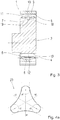
Fig. 1 eine perspektivische Ansicht einer Ausgleichskupplung gemäß einem ersten Ausführungsbeispiel, bei dem eine Außenkontur einer Innennabe und eine Innenkontur einer Hohlnabe jeweils als formschlüssig ineinandergreifende Circulo-Dreiecke ausgebildet sind, -
Fig. 2 eine axiale Draufsicht der Ausgleichskupplung gemäß dem inFig. 1 dargestellten Ausführungsbeispiel, -
Fig. 3 einen Längsschnitt durch die Ausgleichskupplung gemäß dem inFig. 1 dargestellten Ausführungsbeispiel, -
Fig. 4a eine schematische Darstellung einer als Circulo-Dreieck ausgebildeten Außenkontur und/oder Innenkontur, -
Figur 4b eine schematische Darstellung einer als Circulo-Viereck ausgebildeten Außenkontur und/oder Innenkontur, -
Fig. 4c eine schematische Darstellung einer als Circulo-Fünfeck ausgebildeten Außenkontur und/oder Innenkontur und -
Fig. 5 eine elastische Doppel-Torsionskupplung mit einer ersten und zweiten Ausgleichskupplung, die über ein Verbindungsrohr miteinander verbunden sind. - In den
Figuren 1, 2 und3 ist ein erstes Ausführungsbeispiel einer Ausgleichskupplung 1 dargestellt. Die Ausgleichskupplung 1 ist vorzugsweise für den Einsatz in einem Schienenfahrzeug vorgesehen. Hier wird sie im Antriebsstrang, der im Wesentlichen einen Antrieb, ein Getriebe und einen darüber antreibbaren Radwellensatz umfasst, antriebsseitig verbaut. Die Ausgleichskupplung 1 kann hierbei zwischen dem Antrieb und dem Getriebe antriebsseitig verbaut sein, um die Antriebswelle des Antriebs und die Eingangswelle des Getriebes torsionselastisch, achsversatzausgleichend und/oder beugewinkelausgleichend miteinander zu verbinden. Ebenso ist es denkbar, dass die Ausgleichskupplung Bestandteil einer elastischen Doppel-Torsionskupplung ist. Eine derartige Doppel-Torsionskupplung ist beispielsweise inFig. 5 dargestellt, bei der zwei, nachstehend im Detail beschriebene, Ausgleichskupplungen, über ein dazwischen angeordnetes Verbindungsrohr miteinander gekoppelt sind. - Insbesondere gemäß der in
Fig. 1 dargestellten perspektivischen Ansicht sowie der inFig. 2 dargestellten axialen Draufsicht umfasst die Ausgleichskupplung 1 eine Innennabe 2, die mit einer hier nicht dargestellten ersten Welle verbunden werden kann. Die Innennabe 2 ist von einer Hohlnabe 3 der Ausgleichskupplung 1 umschlossen. Mit der Hohlnabe 3 kann eine hier ebenfalls nicht dargestellte zweite Welle drehfest verbunden werden. Die Hohlnabe 3 umschließt die Innennabe 2 in Umfangsrichtung. Die Innennabe 2 ist somit im Innenraum der Hohlnabe 3 angeordnet. - Des Weiteren ist die Hohlnabe 3 von der Innennabe 2 beabstandet, so dass zwischen diesen beiden ein Spalt ausgebildet ist. Zur Ausbildung einer Torsionselastizität umfasst die Ausgleichskupplung 1 ferner ein Ausgleichselement 4. Das Ausgleichselement 4 ist zwischen den beiden Naben 2, 3 angeordnet. Es befindet sich somit im Spalt zwischen der Innennabe 2 und der Hohlnabe 3. Das Ausgleichselement 4 ist elastisch ausgebildet. Durch diese elastisch federnde Wirkung des Ausgleichselementes 4 wird die Ausgleichskupplung 1 torsionselastisch, so dass Drehungleichförmigkeiten des übertragenen Drehmomentes und daraus gegebenenfalls resultierende Schwingungen gedämpft werden.
- Wie insbesondere gemäß
Fig. 1 und Fig. 2 ersichtlich ist, weist die Ausgleichskupplung 1, vorzugsweise die Innenkontur 6 und die Außenkontur 5, eine von einer gewöhnlichen kreisrunden Form abweichende unrunde Form auf. Hierdurch kann vermieden werden, dass die Drehmomente zwischen der Innennabe 2 und der Hohlnabe 3 nicht ausschließlich über auf das Ausgleichselement 4 einwirkende Scherkräfte übertragen wird. Derartige Scherkräfte können nämlich von dem Ausgleichselement 4 schlechter kompensiert werden als Druckkräften, so dass das Ausgleichselement 4 bei einer kreisrunden Ausgleichskupplung 1 eine relativ geringe Lebensdauer hat. - Im Gegensatz dazu weist die vorliegende Ausgleichskupplung 1 eine Außenkontur 5 auf. Die Hohlnabe 3 weist eine Innenkontur 6 auf. Sowohl die Außenkontur 5 als auch die Innenkontur 6 sind unrund ausgebildet. Sie weisen demnach eine von einer kreisrunden Form abweichende Kontur auf. Die Außenkontur 5 der Innennabe 2 und die Innenkontur 6 der Hohlnabe 3 sind derart geformt, dass die Innennabe 2 und die Hohlnabe 3 in Umfangsrichtung formschlüssig ineinandergreifen. Hierdurch könnte somit auch ohne ein dazwischen angeordnetes Ausgleichselement 4 Drehmomente zwischen den beiden Naben 2, 3 übertragen werden. Aufgrund der formschlüssig ineinandergreifenden Naben 2, 3 wird das Ausgleichselement 4 bei Drehmomentübertragung zwischen der Innenkontur 6 der Hohlnabe 3 und der Außenkontur 5 der Innennabe 2 verpresst bzw. zusammengedrückt. Hierdurch wird das Ausgleichselement 4 vorteilhafterweise zumindest teilweise mit einer Druckkomponente beaufschlagt. Da Druckkräften im Vergleich zu Scherkräften geringeren Stress im elastischen Material des Ausgleichselementes 4 hervorrufen, kann hierdurch die Lebensdauer des Ausgleichselementes 4 erhöht werden. Des Weiteren kann selbst bei beschädigtem oder gerissenem Ausgleichselement 4 aufgrund des formschlüssigen Ineinandergreifens eine Drehmomentübertragung zwischen Innennabe 2 und Hohlnabe 3 sichergestellt werden.
- Wie insbesondere aus
Fig. 2 hervorgeht liegt das Ausgleichselement 4 nicht über seinen gesamten Umfang hinweg an der Außenkontur 5 der Innennabe 2 und an der Innenkontur 6 der Hohlnabe 3 an. Stattdessen weist die Außenkontur 5 zumindest einen Außenkontaktabschnitt 7 und die Innenkontur 6 zumindest einen Innenkontaktabschnitt 8 auf. Das Ausgleichselement 4 liegt hierbei mit einer radial inneren Seite am Außenkontaktabschnitt 7 der Innennabe 2 und mit einer radial äußeren Seite am Innenkontaktabschnitt 8 der Hohlnabe 3 an. - Der Außenkontaktabschnitt 7 und der Innenkontaktabschnitt 8 sind zueinander entgegengesetzt gekrümmt. Sowohl der Außenkontaktabschnitt 7 als auch der Innenkontaktabschnitt 8 sind gemäß dem vorliegenden Ausführungsbeispiel konvex gekrümmt, so dass das Ausgleichselement 4 an dieser über ihre gesamte Länge anliegt. Des Weiteren geht aus
Fig. 2 hervor, dass der Außenkontaktabschnitt 7 und der Innenkontaktabschnitt 8 zueinander in unterschiedlichen Winkelintervallen angeordnet sind. Die beiden Kontaktabschnitte 7, 8 sind somit in Umfangsrichtung der Ausgleichskupplung 1 zueinander versetzt angeordnet. - Gemäß dem vorliegenden Ausführungsbeispiel überlappen sich die beiden Kontaktabschnitte 7, 8 in Umfangsrichtung. Infolgedessen weist der Innenkontaktabschnitt 8 und der Außenkontaktabschnitt 7 einen gemeinsamen Überlappungsbereich 9 auf. In diesem Überlappungsbereich 9 liegt das Ausgleichselement 4 sowohl an seiner radial äußeren Seite an dem Innenkontaktabschnitt 8 als auch an seiner radial inneren Seite an dem Außenkontaktabschnitt 7 an.
- In den übrigen Bereichen liegt das Ausgleichselement 4 jeweils nur an einer Seite, nämlich entweder an der Außenkontur 5 oder an der Innenkontur 6 an. Dies wird durch Ausgriffsabschnitte 10, 11 sichergestellt. Demnach weist die Außenkontur 5 der Innennabe 2 zumindest einen Ausgriffsabschnitt 10 auf, der sich in Umfangsrichtung der Innennabe 2 an den Außenkontaktabschnitt 7 anschließt. Der Ausgriffsabschnitt 10 der Innennabe 2 ist dem Innenkontaktabschnitt 8 der Hohlnabe 3 gegenüberliegend angeordnet. Infolgedessen liegt das Ausgleichselement 4 in diesem Bereich ausschließlich an der Hohlnabe 3, nämlich im Innenkontaktabschnitt 8, an. Von der Innennabe 2 ist das Ausgleichselement 4 in diesem Bereich beabstandet. Zwischen dem Ausgleichselement 4 und der Innennabe 2 ist somit ein Innenhohlraum 12 ausgebildet.
- In analoger Weise umfasst die Hohlnabe 3 auch zumindest einen Ausgriffsabschnitt 11. Der Ausgriffsabschnitt 11 der Hohlnabe 3 schließt sich in Umfangsrichtung an den Innenkontaktabschnitt 8 an. Der Ausgriffsabschnitt 11 der Hohlnabe 3 ist dem Außenkontaktabschnitt 7 der Innennabe 2, insbesondere in Radialrichtung, gegenüberliegend angeordnet. Infolgedessen liegt das Ausgleichselement 4 auch in diesem Bereich ausschließlich an einer der beiden Naben 2, 3 an. Demnach liegt das Ausgleichselement 4 in diesem Abschnitt an seiner radial inneren Seite im Außenkontaktabschnitt 7 an der Innennabe 2 an, wohingegen es auf seiner radial äußeren Seite zum Ausgriffsabschnitt 11 der Hohlnabe 3 einen Abstand aufweist. Zwischen der Hohlnabe 3, insbesondere ihrem Ausgriffsabschnitt 11, und dem Ausgleichselement 4 ist somit ein Außenhohlraum 13 ausgebildet.
- Das Ausgleichselement 4 schmiegt sich an den Außenkontaktabschnitt 7 der Innennabe 2 an und geht fließend, im Wesentlichen tangential, auf den Innenkontaktabschnitt 8 der Hohlnabe 3 über.
- Die beiden Ausgriffsabschnitte 10, 11 der Innennabe 2 bzw. der Hohlnabe 3 sind vorliegend konkav gekrümmt. Alternativ könnten diese aber auch keine gebogene sondern eine eckige Form aufweisen. Mittels der gebogenen Konkavform kann jedoch die Außenkontur 5 bzw. die Innenkontur 6 kostengünstiger hergestellt werden.
- Der Außenkontaktabschnitt 7 ist im Vergleich zum Innenkontaktabschnitt 8 stärker gekrümmt. Ebenso ist auch der Ausgriffsabschnitt 10 der Innennabe 2 im Vergleich zum Ausgriffsabschnitt 11 der Hohlnabe 3 stärker gekrümmt.
- Gemäß
Fig. 2 wird infolgedessen bei einer Relativverdrehung der Innennabe 2 gegenüber der Hohlnabe 3 entgegen den Uhrzeigersinn aufgrund des formschlüssigen Ineinandergreifens der beiden Naben 2, 3 das Ausgleichselement 4 zwischen einem Teilbereich des Außenkontaktabschnitts 7 und einen Teilbereich des Innenkontaktabschnitts 8 elastisch zusammengedrückt. Wie bereits vorstehend erwähnt, können hierdurch die auf das Ausgleichselement 4 einwirkenden Scherkräfte reduziert und die Druckkräfte erhöht werden. Gemäß dem vorliegenden Ausführungsbeispiel erfolgt dieses Zusammendrücken des Ausgleichselementes 4 im Wesentlichen im Überlappungsbereich 9. Hierdurch kann die Ausgleichskupplung 1 torsionselastisch ausgebildet werden, so dass Drehungleichförmigkeiten übertragenen Drehmoments kompensiert werden können. - In einem hier nicht dargestellten Ausführungsbeispiel ist es ebenso auch denkbar, dass der Außenkontaktabschnitt 7 und der Innenkontaktabschnitt 8 nicht überlappen, sondern vorzugsweise unmittelbar aneinander angrenzen oder voneinander beabstandet sind. Hierdurch würde demnach erst beim elastischen Verformen des Ausgleichselementes während der Drehmomentübertragung ein entsprechender Überlappungsbereich 9 ausgebildet werden.
- Gemäß
Fig. 2 ist das Ausgleichselement 4 in Umfangsrichtung auf Spannung gehalten. Somit kann sichergestellt werden, dass sich das Ausgleichselement 4 gegenüber den beiden Naben 2, 3 nicht verschiebt. Um die Spannung des Ausgleichselementes 4 einstellen zu können, ist es vorteilhaft, wenn der Außenkontaktabschnitt 7 und/oder der Innenkontaktabschnitt 8 radial nach innen und/oder radial nach außen bewegbar sind. Alternativ ist es ebenso auch denkbar, dass die Krümmung des Außenkontaktabschnitts 7 und/oder des Innenkontaktabschnitts 8 veränderbar ist. - Gemäß dem vorliegenden Ausführungsbeispiel ist das Ausgleichselement 4 als Zahnriemen ausgebildet. Er weist demnach eine Innenverzahnung 14 und eine Außenverzahnung 15 auf. Des Weiteren weist die Innennabe 2 an ihrer Außenkontur 5 zumindest im Bereich des Außenkontaktabschnitts 7 eine Innennabenverzahnung 16 auf. Ebenso weist die Hohlnabe 3 an ihrer Innenkontur 6 eine Hohlnabenverzahnung 17 auf. Diese ist gemäß
Figur 2 zumindest im Innenkontaktabschnitt 8 ausgebildet. - Die Innennabenverzahnung 16 und die Hohlnabenverzahnung 17 greifen nicht ineinander, sondern weisen zueinander einen Abstand auf. Zwischen den Zahnköpfen der gegenüberliegenden Verzahnungen ist somit ein Abstand bzw. Spalt ausgebildet. In diesem radialen Spalt zwischen Innennabenverzahnung 16 und Hohlnabenverzahnung 17 ist das vorzugsweise als Zahnriemen ausgebildete Ausgleichselement 4 angeordnet. Im Bereich des Innenkontaktabschnitts 8 greift das Ausgleichselement 4 mit seiner Außenverzahnung 16 in die Hohlnabenverzahnung 17 ein. Im Außenkontaktabschnitt 7 greift das Ausgleichselement 4 mit seiner Innenverzahnung 14 in die Innennabenverzahnung 16. Hierdurch kann ein Verrutschen des Zahnriemens bzw. des Ausgleichselementes 4 in Umfangsrichtung vermieden werden.
- Der Innenhohlraum 12 und/oder der Außenhohlraum 13 begünstigen unter anderem den Ausgleich größere Beugewinkel. Demnach erlaubt der Innenhohlraum 12 und/oder der Außenhohlraum 13 ein stärkeres Verkippen der beiden Naben 2, 3 zueinander. Dies kann zusätzlich oder alternativ dadurch begünstigt werden, wenn der Außenkontaktabschnitt 7 gemäß dem in
Fig. 3 dargestellten Axialschnitt ballig ausgebildet ist. Zusätzlich oder alternativ kann gemäßFig. 3 auch der Innenkontaktabschnitt 8 ballig ausgebildet sein. Hierbei weist der Innenkontaktabschnitt 8 jedoch vorzugsweise eine an die konvexe Ballenform des Außenkontaktabschnitts 7 angepasste konkave Ballenform auf. - Um ein seitliches Abrutschen des Ausgleichselementes 4 von der Innennabe 2 und/oder von der Hohlnabe 3 vermeiden zu können, ist es vorteilhaft, wenn das Ausgleichselement 4 und der Außenkontaktabschnitt 7 eine sich in Umfangsrichtung erstreckende Nut 18 sowie einen darin formschlüssig eingreifenden Steg 19 aufweisen. Gemäß dem vorliegenden Ausführungsbeispiel ist der Steg 19 an der radialen Innenseite des Ausgleichselementes 4 angeordnet und greift in die an der Außenkontur 5 ausgebildete Nut 18 ein. Es versteht sich von selbst, dass der Steg 19 ebenso auch in der Innennabe 2 und die Nut 18 im Ausgleichselement 4 ausgebildet sein können. Zusätzlich oder alternativ kann eine entsprechende axiale Zentrierung in analoger Weise zwischen dem Ausgleichselement 4 und dem Innenkontaktabschnitt 8 der Hohlnabe 3 ausgebildet sein.
- Wie aus dem insbesondere in
Fig. 2 dargestellten Ausführungsbeispiel hervorgeht, sind die vorstehend beschriebenen Merkmale einzeln oder in beliebiger Kombination alternierend über den Umfang hinweg angeordnet. So weisen die als Circulo-Dreieck ausgebildete Außenkontur 5 sowie Innenkontur 6 drei entsprechend ausgebildete Bereiche auf. Infolgedessen weist die Ausgleichskupplung 1 drei Außenkontaktabschnitte 7, drei Innenkontaktabschnitte 8 und jeweils drei Ausgriffsabschnitte 10, 11 auf. Des Weiteren weist die Ausgleichskupplung 1 gemäß diesem Ausführungsbeispiel sechs Überlappungsbereiche 9 auf. Aus Gründen der Übersichtlichkeit ist jedoch jeweils nur einer dieser Abschnitte bzw. Bereiche mit einem Bezugszeichen versehen. - In einem hier nicht dargestellten alternativen Ausführungsbeispiel ist es aber auch ebenso denkbar, dass die Ausgleichskupplung 1 jeweils nur zwei der vorstehend genannten Abschnitte sowie nur vier Überlappungsbereiche 9 aufweist. Die Innennabe 2 könnte demnach im Wesentlichen eine Knochenform aufweisen. Die Hohlnabe 3 könnte ferner als Oval oder Ellipse ausgebildet sein.
- Alternativ könnte die Ausgleichskupplung 1 gemäß
Fig. 4b und 4c aber auch ebenso mehr als drei derartige Abschnitte aufweisen. Demnach könnte die Außenkontur 5 und/oder die Innenkontur 6 gemäßFig. 4b als Circulo-Dreieck oder gemäßFig. 4c als Circulo-Fünfeck ausgebildet sein. - In den
Figuren 4a ,4b und 4c sind unterschiedliche Ausführungsformen eines Circulo-Polygons 20 dargestellt. Ein Circulo-Polygon zeichnet sich dadurch aus, dass sich sein Umfang aus mehreren Kreissegmenten zusammensetzt. Alternativ oder zusätzlich können alle oder einzelne Segmente aber auch als Bogensegmente, insbesondere Ellipsoid-Segmente, ausgebildet sein. Des Weiteren können auch Teilabschnitte des Circulo-Polygons als Geraden ausgebildet sein. Wie aus denFiguren 4a ,4b und 4c hervorgeht, resultieren die Circulo-Polygone gemäß dem vorliegenden Ausführungsbeispiel aus Teilsegmenten von radial inneren Kreisen c1 bis c5 und radial äußeren Kreisen h1 bis h5. -
Fig. 5 zeigt eine elastische Doppel-Torsionskupplung 21. Diese umfasst zwei Ausgleichskupplungen 22, 23, die gemäß der vorangegangenen Beschreibung ausgebildet sein können. Hierbei können die vorstehend genannten Merkmale einzelnen oder in beliebiger Kombination vorhanden sein. Die beiden Ausgleichskupplungen 22, 23 sind über ein Verbindungsrohr 24 miteinander verbunden. Das Verbindungsrohr 24 ist vorliegend mit den beiden Innennaben 2 der jeweiligen Ausgleichskupplung 22, 23 verbunden. Um eine Unwucht durch elastische Verformung zu vermeiden, weist zumindest eine der beiden Ausgleichskupplungen 22, 23, gemäß dem vorliegenden Ausführungsbeispiele beide, ein Zentrierelement 25 auf. Dieses Zentrierelement 25 zentriert die Innennabe 2 in der Hohlnabe 3. Ein derartiges Zentrierelement 25 kann vorgesehen werden, wenn kein Radialversatz zwischen den beiden Naben 2, 3 ausgeglichen werden muss. Die Zentrierung kann über ein als Gleitlager ausgebildetes Zentrierelement 25 erfolgen. Hierbei ist mindestens eine Gleitfläche 26 des Zentrierelementes 25 sphärisch ausgebildet. Alternativ kann das Zentrierelement 25 aber auch ein Wälzlager, z.B. ein Pendelrollenlager, sein. Hierbei kann der Außenring oder der Innenring des Wälzlager axial verschieblich im jeweils anderen Teil der Nabe 2, 3 gelagert sein. - Die vorliegende Erfindung ist nicht auf die dargestellten und beschriebenen Ausführungsbeispiele beschränkt. Abwandlungen im Rahmen der Patentansprüche sind ebenso möglich wie eine Kombination der Merkmale, auch wenn diese in unterschiedlichen Ausführungsbeispielen dargestellt und beschrieben sind.
-
- 1
- Ausgleichskupplung
- 2
- Innennabe
- 3
- Hohlnabe
- 4
- Ausgleichselement
- 5
- Außenkontur
- 6
- Innenkontur
- 7
- Außenkontaktabschnitt
- 8
- Innenkontaktabschnitt
- 9
- Überlappungsbereich
- 10
- Ausgriffsabschnitt der Innennabe
- 11
- Ausgriffsabschnitt der Hohlnabe
- 12
- Innenhohlraum
- 13
- Außenhohlraum
- 14
- Innenverzahnung
- 15
- Außenverzahnung
- 16
- Innennabenverzahnung
- 17
- Hohlnabenverzahnung
- 18
- Nut
- 19
- Steg
- 20
- Circulo-Polygon
- 21
- Doppel-Torsionskupplung
- 22
- erste Ausgleichskupplung
- 23
- zweite Ausgleichskupplung
- 24
- Verbindungsrohr
- 25
- Zentrierelement
- 26
- Gleitfläche
Claims (19)
- Ausgleichskupplung für ein Schienenfahrzeug und dort zum antriebsseitigen Einsatz, mit einer Innennabe (2) zum drehfesten Verbinden mit einer ersten Welle, mit einer Hohlnabe (3) zur drehfesten Verbindung mit einer zweiten Welle, die die Innennabe (2) in Umfangsrichtung umschließt und von dieser beabstandet ist, und mit einem elastischen Ausgleichselement (4) zum torsionselastischen, achsversatz ausgleichenden und/oder beugewinkelausgleichenden Verbinden der beiden Naben, das zwischen diesen beiden Naben angeordnet ist und die Innennabe (2) in Umfangsrichtung umschließt, wobei die Innennabe (2) eine derart geformte Außenkontur (5) und die Hohlnabe (3) eine derart mit dieser korrespondierende Innenkontur (6) aufweisen, dass die beiden Naben zur Drehmomentübertragung in Umfangsrichtung formschlüssig ineinandergreifen, dadurch gekennzeichnet, dass die Außenkontur (5) und Innenkontur (6) jeweils zumindest einen Ausgriffsabschnitt (10, 11) aufweisen, in dem das Ausgleichselement (4) von der jeweiligen Nabe beabstandet ist.
- Ausgleichskupplung nach dem vorherigen Anspruch, dadurch gekennzeichnet, dass die beiden Naben derart ineinandergreifen, dass das Ausgleichselement (4) bei Drehmomentübertragung zwischen der Innenkontur (6) und der Außenkontur (5) verpressbar und zumindest teilweise auf Druck beanspruchbar ist.
- Ausgleichskupplung nach einem oder mehreren der vorherigen Ansprüche, dadurch gekennzeichnet, dass die Außenkontur (5) zumindest einen Außenkontaktabschnitt (7) und die Innenkontur (6) zumindest einen Innenkontaktabschnitt (8) aufweist, in dem das Ausgleichselement (4) an der jeweiligen Nabe anliegt.
- Ausgleichskupplung nach Anspruch 3, dadurch gekennzeichnet, dass der Außenkontaktabschnitt (7) und der Innenkontaktabschnitt (8) konvex gekrümmt und diese zueinander in Umfangsrichtung versetzt angeordnet sind.
- Ausgleichskupplung nach einem der Anspruch 3 bis 4, dadurch gekennzeichnet, dass der Innenkontaktabschnitt (8) und der Außenkontaktabschnitt (7) einen gemeinsamen Überlappungsbereich (9) aufweisen.
- Ausgleichskupplung nach einem der vorherigen Ansprüche, dadurch gekennzeichnet, dass der Ausgriffsabschnitt (10, 11) der Außenkontur (5) und/oder der Innenkontur (6) konkav gekrümmt und/oder in Radialrichtung dem Kontaktabschnitt der jeweils anderen Nabe gegenüberliegend angeordnet ist.
- Ausgleichskupplung nach einem oder mehreren der vorherigen Ansprüche, dadurch gekennzeichnet, dass zwischen der Innennabe (2) und dem Ausgleichselement (4) zumindest ein Innenhohlraum und/oder zwischen der Hohlnabe (3) und dem Ausgleichselement (4) zumindest ein Außenhohlraum (13) ausgebildet ist.
- Ausgleichskupplung nach einem der vorherigen Ansprüche, dadurch gekennzeichnet, dass der Ausgriffsabschnitt (10) der Außenkontur (5) und der Innenhohlraum (12) in Umfangsrichtung zwischen zwei Außenkontaktabschnitten (7) ausgebildet ist und dass der Ausgriffsabschnitt (11) der Innenkontur (6) und der Außenhohlraum (13) in Umfangsrichtung zwischen zwei Innenkontaktabschnitten (8) ausgebildet ist.
- Ausgleichskupplung nach einem der Ansprüche 3 bis 8, dadurch gekennzeichnet, dass sich die Außenkontur (5) und/oder die Innenkontur (6) über ihren gesamten Umfang hinweg, vorzugsweise abwechselnd, aus mehreren Außenkontakt-, Innenkontakt- und/oder Ausgriffsabschnitten zusammensetzen, die ineinander übergehen.
- Ausgleichskupplung nach einem oder mehreren der vorherigen Ansprüche, dadurch gekennzeichnet, dass die Außenkontakt-, Innenkontakt- und/oder Ausgriffsabschnitte als Kreissegmente ausgebildet sind und/oder die Form der Außenkontur (5) und/oder der Innenkontur (6) ein Circulo-Polygon, insbesondere ein Circulo-Dreieck, Circulo-Viereck und/oder Circulo-Fünfeck, ist.
- Ausgleichskupplung nach einem der Ansprüche 3 bis 10, dadurch gekennzeichnet, dass der Außenkontaktabschnitt (7) der Innennabe (2) und/oder der Innenkontaktabschnitt (8) der Hohlnabe (3) zum Spannen des Ausgleichselements (4) in Radialrichtung verstellbar ist.
- Ausgleichskupplung nach einem oder mehreren der vorherigen Ansprüche, dadurch gekennzeichnet, dass die Innennabe (2) und/oder die Hohlnabe (3) zur Wartung oder zum Austausch des Ausgleichselement (4)s mehrteilig und/oder teilbar ausgebildet ist.
- Ausgleichskupplung nach einem der Ansprüche 3 bis 12, dadurch gekennzeichnet, dass der Außenkontaktabschnitt (7) und/oder der Innenkontaktabschnitt (8) im Axialschnitt ballig ausgebildet sind.
- Ausgleichskupplung nach einem der Ansprüche 3 bis 14, dadurch gekennzeichnet, dass das Ausgleichselement (4) zur axialen Zentrierung eine sich in Umfangsrichtung erstreckende Nut und/oder einen Steg aufweist, der formschlüssig in einen sich in Umfangsrichtung erstreckenden Zentriersteg und/oder eine Zentriernut des Außenkontaktabschnitts (7) und/oder des Innenkontaktabschnitts (8) eingreift.
- Ausgleichskupplung nach einem oder mehreren der vorherigen Ansprüche, dadurch gekennzeichnet, dass das Ausgleichselement (4) in einem Verschlussbereich teilbar ist und der Verschlussbereich zur Außenkontur (5) und/oder zur Innenkontur (6) beabstandet ist.
- Ausgleichskupplung nach einem oder mehreren der vorherigen Ansprüche, dadurch gekennzeichnet, dass das Ausgleichselement (4) zumindest einen, insbesondere armierten, Zahnriemen umfasst, der formschlüssig, kraftschlüssig und/oder stoffschlüssig an dessen Verzahnung befestigte Eingriffselemente aufweist, und dass der Außenkontaktabschnitt (7) und/oder der Innenkontaktabschnitt (8) eine Verzahnung aufweisen.
- Ausgleichskupplung nach einem oder mehreren der vorherigen Ansprüche, dadurch gekennzeichnet, dass das Ausgleichselement (4) einen mit der Innennabe (2) verzahnten Innenzahnriemen, einen mit der Hohlnabe (3) verzahnten Außenzahnriemen und ein zwischen diesen beiden angeordnetes oder mit diesen verzahntes Zwischenelement umfasst, wobei das Zwischenelement unelastisch ist.
- Ausgleichskupplung nach einem oder mehreren der vorherigen Ansprüche, dadurch gekennzeichnet, dass die Ausgleichskupplung ein Zentrierelement aufweist, das die Innennabe (2) in der Hohlnabe (3) zentriert, wobei das Zentrierelement ein Gleitlager mit zumindest einer sphärischen Gleitfläche oder ein axial verschiebbares Wälzlager ist.
- Antriebsstrang, insbesondere für ein Schienenfahrzeug, mit einem Antrieb, insbesondere einem Elektromotor, einem Getriebe, einem antreibbaren Radwellensatz und einer torsionselastischen Ausgleichskupplung, die antriebsseitig zwischen dem Antrieb und dem Getriebe oder abtriebsseitig zwischen dem Getriebe und dem Radwellensatz angeordnet ist, dadurch gekennzeichnet, dass die Ausgleichskupplung nach einem oder mehreren der vorherigen Ansprüche ausgebildet ist.
Applications Claiming Priority (2)
| Application Number | Priority Date | Filing Date | Title |
|---|---|---|---|
| DE102015205501.9A DE102015205501A1 (de) | 2015-03-26 | 2015-03-26 | Elastische Ausgleichskupplung mit formschlüssig ineinandergreifenden Naben |
| PCT/EP2016/054040 WO2016150645A1 (de) | 2015-03-26 | 2016-02-26 | Elastische ausgleichskupplung mit formschlüssig ineinandergreifenden naben |
Publications (2)
| Publication Number | Publication Date |
|---|---|
| EP3274604A1 EP3274604A1 (de) | 2018-01-31 |
| EP3274604B1 true EP3274604B1 (de) | 2019-08-28 |
Family
ID=55436104
Family Applications (1)
| Application Number | Title | Priority Date | Filing Date |
|---|---|---|---|
| EP16706360.1A Active EP3274604B1 (de) | 2015-03-26 | 2016-02-26 | Elastische ausgleichskupplung mit formschlüssig ineinandergreifenden naben |
Country Status (4)
| Country | Link |
|---|---|
| EP (1) | EP3274604B1 (de) |
| CN (1) | CN107407341B (de) |
| DE (1) | DE102015205501A1 (de) |
| WO (1) | WO2016150645A1 (de) |
Families Citing this family (1)
| Publication number | Priority date | Publication date | Assignee | Title |
|---|---|---|---|---|
| DE102018122977B4 (de) * | 2018-09-19 | 2026-02-12 | Muhr Und Bender Kg | Wellenanordnung |
Family Cites Families (10)
| Publication number | Priority date | Publication date | Assignee | Title |
|---|---|---|---|---|
| US2948129A (en) * | 1958-06-23 | 1960-08-09 | Schwitzer Corp | Elliptical vibration damper |
| DE2053326A1 (de) * | 1970-10-30 | 1972-05-04 | Daimler-Benz Ag, 7000 Stuttgart | Gelenk zum elastischen Kuppeln zweier Wellenteile |
| BE800771A (fr) * | 1973-06-12 | 1973-10-01 | Kupplungstechnik Gmbh | Manchon d'accouplement a torsion elastique |
| AT384405B (de) * | 1985-07-22 | 1987-11-10 | Supervis Ets | Laengenveraenderbare lenkspindel fuer lenkvorrichtungen bei kraftfahrzeugen |
| DE10325740A1 (de) | 2003-06-06 | 2004-12-23 | Volkswagen Ag | Torsionselastische Kupplung für zwei Naben |
| KR100708876B1 (ko) * | 2005-10-10 | 2007-04-18 | 주식회사 만도 | 조향장치의 슬립 조인트 |
| DE102008016798B4 (de) * | 2008-04-02 | 2015-12-10 | Schaeffler Technologies AG & Co. KG | Wälzlager sowie Lenkgetriebe mit einem derartigen Wälzlager |
| WO2009153417A1 (fr) * | 2008-06-20 | 2009-12-23 | Zf Systemes De Direction Nacam, S.A.S. | Dispositif d'accouplement à billes à maintien articulé de deux arbres coulissants |
| CN103982559B (zh) * | 2008-06-20 | 2017-05-10 | 采埃孚转向机系统纳凯姆联合股份公司 | 用于两个滑动轴的带有铰链连接的球联接装置 |
| DE102011008396A1 (de) * | 2011-01-12 | 2012-07-12 | SGF SüDDEUTSCHE GELENKSCHEIBENFABRIK GMBH & CO. KG | Kupplung zum dämpfenden Verbinden zweier Wellenabschnitte insbesondere einer Lenkwelle, sowie Lenkwelle und Verfahren zu Herstellung einer entsprechenden Kupplung |
-
2015
- 2015-03-26 DE DE102015205501.9A patent/DE102015205501A1/de not_active Withdrawn
-
2016
- 2016-02-26 CN CN201680014887.7A patent/CN107407341B/zh not_active Expired - Fee Related
- 2016-02-26 EP EP16706360.1A patent/EP3274604B1/de active Active
- 2016-02-26 WO PCT/EP2016/054040 patent/WO2016150645A1/de not_active Ceased
Non-Patent Citations (1)
| Title |
|---|
| None * |
Also Published As
| Publication number | Publication date |
|---|---|
| DE102015205501A1 (de) | 2016-09-29 |
| WO2016150645A1 (de) | 2016-09-29 |
| CN107407341B (zh) | 2019-10-22 |
| EP3274604A1 (de) | 2018-01-31 |
| CN107407341A (zh) | 2017-11-28 |
Similar Documents
| Publication | Publication Date | Title |
|---|---|---|
| EP2132458B1 (de) | Koaxialgetriebe, insbesondere hohlwellengetriebe für die industrielle antriebstechnik | |
| EP2758684B1 (de) | Kupplung mit kupplungsring auf zwei kupplungsteilen und zugehöriger kupplungsring | |
| DE102011008396A1 (de) | Kupplung zum dämpfenden Verbinden zweier Wellenabschnitte insbesondere einer Lenkwelle, sowie Lenkwelle und Verfahren zu Herstellung einer entsprechenden Kupplung | |
| DE102007007362A1 (de) | Verstellmechanismus | |
| AT520740B1 (de) | Zahnrad | |
| EP2924308A1 (de) | Elastische doppel-torsionskupplung | |
| WO2017041802A1 (de) | Getriebe mit elastischem zahnrad | |
| EP0785370B1 (de) | Kreuzgelenkanordnung für eine Gelenkwelle | |
| EP0499163B1 (de) | Getriebekomponente mit Keilverzahnung | |
| EP2427667A2 (de) | Gleichlaufgelenk und gelenkwelle | |
| DE102016110389A1 (de) | Elektromotor mit Schwingungsentkopplungsanordnung zur drehfesten Verbindung hin zum Getriebe | |
| EP2500595A1 (de) | Wellenkupplung | |
| EP3274604B1 (de) | Elastische ausgleichskupplung mit formschlüssig ineinandergreifenden naben | |
| EP2148106B1 (de) | Drehmomentübertragungseinrichtung | |
| DE102014204221B4 (de) | Ausgleichskupplung mit Distanzelement sowie Kupplungsanordnung | |
| DE4228488A1 (de) | Elastische Wellenkupplung | |
| EP1691095B1 (de) | Axiale Isolierung für ein kardanisches Kreuzgelenk | |
| EP4045806B1 (de) | Kupplung | |
| EP1382870B1 (de) | Elastische Kupplung | |
| EP1723345B1 (de) | Kreuzgelenkanordnung | |
| DE202017101823U1 (de) | Tonnenkupplung, insbesondere für eine Seiltrommelgelenkverbindung eines Hubwerks | |
| DE102011088327A1 (de) | Kreuzgelenkwelle | |
| DE202010003324U1 (de) | Sechsrund-Profil zur Übertragung eines Drehmomentes | |
| DE970740C (de) | Elastische Wellenkupplung | |
| EP1530685B1 (de) | Anschlusselement zur verbindung von gelenkspindeln mit anschlussaggregaten, insbesondere trefferhalterung mit konischer zentrierung |
Legal Events
| Date | Code | Title | Description |
|---|---|---|---|
| STAA | Information on the status of an ep patent application or granted ep patent |
Free format text: STATUS: THE INTERNATIONAL PUBLICATION HAS BEEN MADE |
|
| PUAI | Public reference made under article 153(3) epc to a published international application that has entered the european phase |
Free format text: ORIGINAL CODE: 0009012 |
|
| STAA | Information on the status of an ep patent application or granted ep patent |
Free format text: STATUS: REQUEST FOR EXAMINATION WAS MADE |
|
| 17P | Request for examination filed |
Effective date: 20170814 |
|
| AK | Designated contracting states |
Kind code of ref document: A1 Designated state(s): AL AT BE BG CH CY CZ DE DK EE ES FI FR GB GR HR HU IE IS IT LI LT LU LV MC MK MT NL NO PL PT RO RS SE SI SK SM TR |
|
| AX | Request for extension of the european patent |
Extension state: BA ME |
|
| DAV | Request for validation of the european patent (deleted) | ||
| DAX | Request for extension of the european patent (deleted) | ||
| GRAP | Despatch of communication of intention to grant a patent |
Free format text: ORIGINAL CODE: EPIDOSNIGR1 |
|
| STAA | Information on the status of an ep patent application or granted ep patent |
Free format text: STATUS: GRANT OF PATENT IS INTENDED |
|
| INTG | Intention to grant announced |
Effective date: 20181221 |
|
| GRAJ | Information related to disapproval of communication of intention to grant by the applicant or resumption of examination proceedings by the epo deleted |
Free format text: ORIGINAL CODE: EPIDOSDIGR1 |
|
| STAA | Information on the status of an ep patent application or granted ep patent |
Free format text: STATUS: REQUEST FOR EXAMINATION WAS MADE |
|
| INTC | Intention to grant announced (deleted) | ||
| GRAP | Despatch of communication of intention to grant a patent |
Free format text: ORIGINAL CODE: EPIDOSNIGR1 |
|
| STAA | Information on the status of an ep patent application or granted ep patent |
Free format text: STATUS: GRANT OF PATENT IS INTENDED |
|
| INTG | Intention to grant announced |
Effective date: 20190319 |
|
| GRAS | Grant fee paid |
Free format text: ORIGINAL CODE: EPIDOSNIGR3 |
|
| GRAA | (expected) grant |
Free format text: ORIGINAL CODE: 0009210 |
|
| STAA | Information on the status of an ep patent application or granted ep patent |
Free format text: STATUS: THE PATENT HAS BEEN GRANTED |
|
| AK | Designated contracting states |
Kind code of ref document: B1 Designated state(s): AL AT BE BG CH CY CZ DE DK EE ES FI FR GB GR HR HU IE IS IT LI LT LU LV MC MK MT NL NO PL PT RO RS SE SI SK SM TR |
|
| REG | Reference to a national code |
Ref country code: GB Ref legal event code: FG4D Free format text: NOT ENGLISH |
|
| REG | Reference to a national code |
Ref country code: CH Ref legal event code: EP |
|
| REG | Reference to a national code |
Ref country code: DE Ref legal event code: R096 Ref document number: 502016006293 Country of ref document: DE |
|
| REG | Reference to a national code |
Ref country code: AT Ref legal event code: REF Ref document number: 1172781 Country of ref document: AT Kind code of ref document: T Effective date: 20190915 |
|
| REG | Reference to a national code |
Ref country code: IE Ref legal event code: FG4D Free format text: LANGUAGE OF EP DOCUMENT: GERMAN |
|
| REG | Reference to a national code |
Ref country code: NL Ref legal event code: MP Effective date: 20190828 |
|
| REG | Reference to a national code |
Ref country code: LT Ref legal event code: MG4D |
|
| PG25 | Lapsed in a contracting state [announced via postgrant information from national office to epo] |
Ref country code: PT Free format text: LAPSE BECAUSE OF FAILURE TO SUBMIT A TRANSLATION OF THE DESCRIPTION OR TO PAY THE FEE WITHIN THE PRESCRIBED TIME-LIMIT Effective date: 20191230 Ref country code: FI Free format text: LAPSE BECAUSE OF FAILURE TO SUBMIT A TRANSLATION OF THE DESCRIPTION OR TO PAY THE FEE WITHIN THE PRESCRIBED TIME-LIMIT Effective date: 20190828 Ref country code: NO Free format text: LAPSE BECAUSE OF FAILURE TO SUBMIT A TRANSLATION OF THE DESCRIPTION OR TO PAY THE FEE WITHIN THE PRESCRIBED TIME-LIMIT Effective date: 20191128 Ref country code: SE Free format text: LAPSE BECAUSE OF FAILURE TO SUBMIT A TRANSLATION OF THE DESCRIPTION OR TO PAY THE FEE WITHIN THE PRESCRIBED TIME-LIMIT Effective date: 20190828 Ref country code: HR Free format text: LAPSE BECAUSE OF FAILURE TO SUBMIT A TRANSLATION OF THE DESCRIPTION OR TO PAY THE FEE WITHIN THE PRESCRIBED TIME-LIMIT Effective date: 20190828 Ref country code: LT Free format text: LAPSE BECAUSE OF FAILURE TO SUBMIT A TRANSLATION OF THE DESCRIPTION OR TO PAY THE FEE WITHIN THE PRESCRIBED TIME-LIMIT Effective date: 20190828 Ref country code: NL Free format text: LAPSE BECAUSE OF FAILURE TO SUBMIT A TRANSLATION OF THE DESCRIPTION OR TO PAY THE FEE WITHIN THE PRESCRIBED TIME-LIMIT Effective date: 20190828 Ref country code: BG Free format text: LAPSE BECAUSE OF FAILURE TO SUBMIT A TRANSLATION OF THE DESCRIPTION OR TO PAY THE FEE WITHIN THE PRESCRIBED TIME-LIMIT Effective date: 20191128 |
|
| PG25 | Lapsed in a contracting state [announced via postgrant information from national office to epo] |
Ref country code: LV Free format text: LAPSE BECAUSE OF FAILURE TO SUBMIT A TRANSLATION OF THE DESCRIPTION OR TO PAY THE FEE WITHIN THE PRESCRIBED TIME-LIMIT Effective date: 20190828 Ref country code: AL Free format text: LAPSE BECAUSE OF FAILURE TO SUBMIT A TRANSLATION OF THE DESCRIPTION OR TO PAY THE FEE WITHIN THE PRESCRIBED TIME-LIMIT Effective date: 20190828 Ref country code: GR Free format text: LAPSE BECAUSE OF FAILURE TO SUBMIT A TRANSLATION OF THE DESCRIPTION OR TO PAY THE FEE WITHIN THE PRESCRIBED TIME-LIMIT Effective date: 20191129 Ref country code: ES Free format text: LAPSE BECAUSE OF FAILURE TO SUBMIT A TRANSLATION OF THE DESCRIPTION OR TO PAY THE FEE WITHIN THE PRESCRIBED TIME-LIMIT Effective date: 20190828 Ref country code: IS Free format text: LAPSE BECAUSE OF FAILURE TO SUBMIT A TRANSLATION OF THE DESCRIPTION OR TO PAY THE FEE WITHIN THE PRESCRIBED TIME-LIMIT Effective date: 20191228 Ref country code: RS Free format text: LAPSE BECAUSE OF FAILURE TO SUBMIT A TRANSLATION OF THE DESCRIPTION OR TO PAY THE FEE WITHIN THE PRESCRIBED TIME-LIMIT Effective date: 20190828 |
|
| PG25 | Lapsed in a contracting state [announced via postgrant information from national office to epo] |
Ref country code: TR Free format text: LAPSE BECAUSE OF FAILURE TO SUBMIT A TRANSLATION OF THE DESCRIPTION OR TO PAY THE FEE WITHIN THE PRESCRIBED TIME-LIMIT Effective date: 20190828 |
|
| PG25 | Lapsed in a contracting state [announced via postgrant information from national office to epo] |
Ref country code: RO Free format text: LAPSE BECAUSE OF FAILURE TO SUBMIT A TRANSLATION OF THE DESCRIPTION OR TO PAY THE FEE WITHIN THE PRESCRIBED TIME-LIMIT Effective date: 20190828 Ref country code: PL Free format text: LAPSE BECAUSE OF FAILURE TO SUBMIT A TRANSLATION OF THE DESCRIPTION OR TO PAY THE FEE WITHIN THE PRESCRIBED TIME-LIMIT Effective date: 20190828 Ref country code: IT Free format text: LAPSE BECAUSE OF FAILURE TO SUBMIT A TRANSLATION OF THE DESCRIPTION OR TO PAY THE FEE WITHIN THE PRESCRIBED TIME-LIMIT Effective date: 20190828 Ref country code: DK Free format text: LAPSE BECAUSE OF FAILURE TO SUBMIT A TRANSLATION OF THE DESCRIPTION OR TO PAY THE FEE WITHIN THE PRESCRIBED TIME-LIMIT Effective date: 20190828 Ref country code: EE Free format text: LAPSE BECAUSE OF FAILURE TO SUBMIT A TRANSLATION OF THE DESCRIPTION OR TO PAY THE FEE WITHIN THE PRESCRIBED TIME-LIMIT Effective date: 20190828 |
|
| PG25 | Lapsed in a contracting state [announced via postgrant information from national office to epo] |
Ref country code: SK Free format text: LAPSE BECAUSE OF FAILURE TO SUBMIT A TRANSLATION OF THE DESCRIPTION OR TO PAY THE FEE WITHIN THE PRESCRIBED TIME-LIMIT Effective date: 20190828 Ref country code: CZ Free format text: LAPSE BECAUSE OF FAILURE TO SUBMIT A TRANSLATION OF THE DESCRIPTION OR TO PAY THE FEE WITHIN THE PRESCRIBED TIME-LIMIT Effective date: 20190828 Ref country code: SM Free format text: LAPSE BECAUSE OF FAILURE TO SUBMIT A TRANSLATION OF THE DESCRIPTION OR TO PAY THE FEE WITHIN THE PRESCRIBED TIME-LIMIT Effective date: 20190828 Ref country code: IS Free format text: LAPSE BECAUSE OF FAILURE TO SUBMIT A TRANSLATION OF THE DESCRIPTION OR TO PAY THE FEE WITHIN THE PRESCRIBED TIME-LIMIT Effective date: 20200224 |
|
| REG | Reference to a national code |
Ref country code: DE Ref legal event code: R097 Ref document number: 502016006293 Country of ref document: DE |
|
| PLBE | No opposition filed within time limit |
Free format text: ORIGINAL CODE: 0009261 |
|
| STAA | Information on the status of an ep patent application or granted ep patent |
Free format text: STATUS: NO OPPOSITION FILED WITHIN TIME LIMIT |
|
| PG2D | Information on lapse in contracting state deleted |
Ref country code: IS |
|
| 26N | No opposition filed |
Effective date: 20200603 |
|
| PG25 | Lapsed in a contracting state [announced via postgrant information from national office to epo] |
Ref country code: SI Free format text: LAPSE BECAUSE OF FAILURE TO SUBMIT A TRANSLATION OF THE DESCRIPTION OR TO PAY THE FEE WITHIN THE PRESCRIBED TIME-LIMIT Effective date: 20190828 |
|
| REG | Reference to a national code |
Ref country code: DE Ref legal event code: R119 Ref document number: 502016006293 Country of ref document: DE |
|
| REG | Reference to a national code |
Ref country code: CH Ref legal event code: PL |
|
| GBPC | Gb: european patent ceased through non-payment of renewal fee |
Effective date: 20200226 |
|
| REG | Reference to a national code |
Ref country code: BE Ref legal event code: MM Effective date: 20200229 |
|
| PG25 | Lapsed in a contracting state [announced via postgrant information from national office to epo] |
Ref country code: MC Free format text: LAPSE BECAUSE OF FAILURE TO SUBMIT A TRANSLATION OF THE DESCRIPTION OR TO PAY THE FEE WITHIN THE PRESCRIBED TIME-LIMIT Effective date: 20190828 Ref country code: LU Free format text: LAPSE BECAUSE OF NON-PAYMENT OF DUE FEES Effective date: 20200226 |
|
| PG25 | Lapsed in a contracting state [announced via postgrant information from national office to epo] |
Ref country code: CH Free format text: LAPSE BECAUSE OF NON-PAYMENT OF DUE FEES Effective date: 20200229 Ref country code: LI Free format text: LAPSE BECAUSE OF NON-PAYMENT OF DUE FEES Effective date: 20200229 |
|
| PG25 | Lapsed in a contracting state [announced via postgrant information from national office to epo] |
Ref country code: DE Free format text: LAPSE BECAUSE OF NON-PAYMENT OF DUE FEES Effective date: 20200901 Ref country code: IE Free format text: LAPSE BECAUSE OF NON-PAYMENT OF DUE FEES Effective date: 20200226 Ref country code: FR Free format text: LAPSE BECAUSE OF NON-PAYMENT OF DUE FEES Effective date: 20200229 Ref country code: GB Free format text: LAPSE BECAUSE OF NON-PAYMENT OF DUE FEES Effective date: 20200226 |
|
| PG25 | Lapsed in a contracting state [announced via postgrant information from national office to epo] |
Ref country code: BE Free format text: LAPSE BECAUSE OF NON-PAYMENT OF DUE FEES Effective date: 20200229 |
|
| REG | Reference to a national code |
Ref country code: AT Ref legal event code: MM01 Ref document number: 1172781 Country of ref document: AT Kind code of ref document: T Effective date: 20210226 |
|
| PG25 | Lapsed in a contracting state [announced via postgrant information from national office to epo] |
Ref country code: AT Free format text: LAPSE BECAUSE OF NON-PAYMENT OF DUE FEES Effective date: 20210226 |
|
| PG25 | Lapsed in a contracting state [announced via postgrant information from national office to epo] |
Ref country code: MT Free format text: LAPSE BECAUSE OF FAILURE TO SUBMIT A TRANSLATION OF THE DESCRIPTION OR TO PAY THE FEE WITHIN THE PRESCRIBED TIME-LIMIT Effective date: 20190828 Ref country code: CY Free format text: LAPSE BECAUSE OF FAILURE TO SUBMIT A TRANSLATION OF THE DESCRIPTION OR TO PAY THE FEE WITHIN THE PRESCRIBED TIME-LIMIT Effective date: 20190828 |
|
| PG25 | Lapsed in a contracting state [announced via postgrant information from national office to epo] |
Ref country code: MK Free format text: LAPSE BECAUSE OF FAILURE TO SUBMIT A TRANSLATION OF THE DESCRIPTION OR TO PAY THE FEE WITHIN THE PRESCRIBED TIME-LIMIT Effective date: 20190828 |