EP3278024B1 - Brûleur à gaz avec couvercle de brûleur - Google Patents
Brûleur à gaz avec couvercle de brûleur Download PDFInfo
- Publication number
- EP3278024B1 EP3278024B1 EP16708456.5A EP16708456A EP3278024B1 EP 3278024 B1 EP3278024 B1 EP 3278024B1 EP 16708456 A EP16708456 A EP 16708456A EP 3278024 B1 EP3278024 B1 EP 3278024B1
- Authority
- EP
- European Patent Office
- Prior art keywords
- gas
- gas distribution
- burner
- segment
- section
- Prior art date
- Legal status (The legal status is an assumption and is not a legal conclusion. Google has not performed a legal analysis and makes no representation as to the accuracy of the status listed.)
- Active
Links
Images




Classifications
-
- F—MECHANICAL ENGINEERING; LIGHTING; HEATING; WEAPONS; BLASTING
- F24—HEATING; RANGES; VENTILATING
- F24C—DOMESTIC STOVES OR RANGES ; DETAILS OF DOMESTIC STOVES OR RANGES, OF GENERAL APPLICATION
- F24C3/00—Stoves or ranges for gaseous fuels
- F24C3/08—Arrangement or mounting of burners
- F24C3/082—Arrangement or mounting of burners on stoves
-
- F—MECHANICAL ENGINEERING; LIGHTING; HEATING; WEAPONS; BLASTING
- F23—COMBUSTION APPARATUS; COMBUSTION PROCESSES
- F23D—BURNERS
- F23D14/00—Burners for combustion of a gas, e.g. of a gas stored under pressure as a liquid
- F23D14/02—Premix gas burners, i.e. in which gaseous fuel is mixed with combustion air upstream of the combustion zone
- F23D14/04—Premix gas burners, i.e. in which gaseous fuel is mixed with combustion air upstream of the combustion zone induction type, e.g. Bunsen burner
- F23D14/06—Premix gas burners, i.e. in which gaseous fuel is mixed with combustion air upstream of the combustion zone induction type, e.g. Bunsen burner with radial outlets at the burner head
-
- F—MECHANICAL ENGINEERING; LIGHTING; HEATING; WEAPONS; BLASTING
- F23—COMBUSTION APPARATUS; COMBUSTION PROCESSES
- F23D—BURNERS
- F23D14/00—Burners for combustion of a gas, e.g. of a gas stored under pressure as a liquid
- F23D14/02—Premix gas burners, i.e. in which gaseous fuel is mixed with combustion air upstream of the combustion zone
- F23D14/04—Premix gas burners, i.e. in which gaseous fuel is mixed with combustion air upstream of the combustion zone induction type, e.g. Bunsen burner
- F23D14/06—Premix gas burners, i.e. in which gaseous fuel is mixed with combustion air upstream of the combustion zone induction type, e.g. Bunsen burner with radial outlets at the burner head
- F23D14/065—Premix gas burners, i.e. in which gaseous fuel is mixed with combustion air upstream of the combustion zone induction type, e.g. Bunsen burner with radial outlets at the burner head with injector axis inclined to the burner head axis
-
- F—MECHANICAL ENGINEERING; LIGHTING; HEATING; WEAPONS; BLASTING
- F23—COMBUSTION APPARATUS; COMBUSTION PROCESSES
- F23D—BURNERS
- F23D14/00—Burners for combustion of a gas, e.g. of a gas stored under pressure as a liquid
- F23D14/20—Non-premix gas burners, i.e. in which gaseous fuel is mixed with combustion air on arrival at the combustion zone
-
- F—MECHANICAL ENGINEERING; LIGHTING; HEATING; WEAPONS; BLASTING
- F23—COMBUSTION APPARATUS; COMBUSTION PROCESSES
- F23D—BURNERS
- F23D14/00—Burners for combustion of a gas, e.g. of a gas stored under pressure as a liquid
- F23D14/46—Details
- F23D14/48—Nozzles
- F23D14/58—Nozzles characterised by the shape or arrangement of the outlet or outlets from the nozzle, e.g. of annular configuration
-
- F—MECHANICAL ENGINEERING; LIGHTING; HEATING; WEAPONS; BLASTING
- F24—HEATING; RANGES; VENTILATING
- F24C—DOMESTIC STOVES OR RANGES ; DETAILS OF DOMESTIC STOVES OR RANGES, OF GENERAL APPLICATION
- F24C3/00—Stoves or ranges for gaseous fuels
- F24C3/08—Arrangement or mounting of burners
-
- F—MECHANICAL ENGINEERING; LIGHTING; HEATING; WEAPONS; BLASTING
- F23—COMBUSTION APPARATUS; COMBUSTION PROCESSES
- F23D—BURNERS
- F23D2900/00—Special features of, or arrangements for burners using fluid fuels or solid fuels suspended in a carrier gas
- F23D2900/14—Special features of gas burners
- F23D2900/14062—Special features of gas burners for cooking ranges having multiple flame rings
-
- F—MECHANICAL ENGINEERING; LIGHTING; HEATING; WEAPONS; BLASTING
- F23—COMBUSTION APPARATUS; COMBUSTION PROCESSES
- F23D—BURNERS
- F23D2900/00—Special features of, or arrangements for burners using fluid fuels or solid fuels suspended in a carrier gas
- F23D2900/14—Special features of gas burners
- F23D2900/14063—Special features of gas burners for cooking ranges having one flame ring fed by multiple venturis
Definitions
- the present invention relates to a gas burner for a Marshsgarmeld.
- Gas burners for household cooking appliances comprise a burner lower part, which can be fastened to a hob plate and a burner cover which can be placed on the burner lower part. Between the burner base and the burner cover a mixing space is provided, in which fuel gas mixes with primary air.
- the burner cap has radially arranged gas distribution channels, which are adapted to distribute the fuel gas / air mixture evenly.
- the US 5,690,483 A describes a gas burner with a burner lower part, a burner cover and an intermediate piece arranged between the burner base and the burner cover. At the burner lower part and the intermediate piece in each case semicircular gas distribution channels are provided, which form circular gas outlet openings in an assembly of the burner lower part and the intermediate piece.
- the US 6,095,802 A shows a gas burner with a burner base and a burner cap, which is placed on the burner base. At the burner lower part and the burner cover each semi-circular gas distribution channels are provided, which form circular gas outlet openings in an assembly of the burner base and the burner cover.
- the FR 461 634 A describes a gas burner with multiple burner rings, which are arranged one above the other. There are provided T-shaped gas outlet openings.
- an object of the present invention is to provide an improved burner cap for a gas burner.
- the burner cap comprises a disc-shaped base portion and one with the
- the gas distributor section includes first gas distribution channels extending radially from an inner surface of the gas distribution section toward an outer edge of the base section, each first gas distribution channel extending through the gas distribution section and having a T-shaped cross-sectional geometry extending in the direction of the first gas distribution channel Base section is pioneeringly open, wherein a T-shaped gas outlet opening is defined by each first gas distribution channel and an upper edge of the burner lower part, wherein the gas distributor section comprises second gas distribution channels, which extend radially from the inner surface of the gas distributor portion in the direction of the outer edge of the base portion, wherein each second Gas distributor passage extends through the gas distributor portion and has a semicircular cross-sectional geometry, which is pioneering open in the direction of the base portion t, wherein a gas outlet opening is defined by each second gas distribution channel and the upper edge of the burner lower part,
- the T-shaped cross-sectional geometry of the gas distribution channels makes it possible to reduce the height of the burner cap in comparison to known rectangular gas distribution channels. This can make the gas burner flatter.
- a flat construction of the gas burner is particularly advantageous in gas stoves with gas burners arranged on a glass ceramic plate.
- the T-shaped cross-sectional geometry leads to an improved efficiency compared to known burner caps with rectangular gas distribution channels. Due to the T-shaped cross-sectional geometry, the air / fuel gas mixture flows out particularly evenly. This reduces the carbon monoxide and soot emissions.
- the gas distribution channels are preferably inclined and arranged in the direction of the base portion of the burner cover upwards. The thus achievable flame angle improves the efficiency of the gas burner again.
- the base portion is preferably circular.
- the base section and the gas distributor section are formed in one piece of material.
- the T-shaped cross-sectional geometry has a horizontal portion and a vertical portion, wherein the horizontal portion is directionally open in the direction of the base portion.
- the open side of the T-shaped cross-sectional geometry is closed when placing the burner cover on a burner lower part in the transmitted sense by an upper edge of the burner lower part, so that a T-shaped gas outlet opening is defined by each gas distribution channel and the upper edge.
- a mixing space available by the fuel mixes with primary air.
- the gas distributor section serves for the uniform distribution of the fuel gas / air mixture.
- the horizontal section is 1.5 times to 6 times, preferably 2 times to 5 times, more preferably 2.5 times to 4 times as wide as the vertical section.
- the gas distribution channels can be milled into the gas distributor section.
- the gas distribution channels can be introduced into the gas distributor section with the aid of a primary shaping method, such as die casting.
- the vertical section extends 1.5 times to 6 times, preferably 2 times to 5 times, more preferably 2.5 times to 4 times as deeply into the gas distributor section as the horizontal section.
- the first gas distribution channel passes through the gas distributor section over its entire thickness.
- the first gas distributor ducts are distributed uniformly over a circumference of the gas distributor section.
- the first gas distribution channels preferably run obliquely in the direction of the outer edge of the base section, starting from the inner surface of the gas distributor section.
- the inner surface of the gas distributor section is inclined at an angle to the base section.
- the fuel gas / air mixture can flow into the gas distribution channels in a particularly simple manner.
- the inner surface is inclined at an angle of 40 ° to 45 ° relative to the central portion of the base portion.
- the burner cover has an annular groove which runs around the gas distributor section.
- the annular groove may, for example, have a quarter-circle-shaped cross-sectional geometry.
- the vertical portion of the T-shaped gas outlet channels preferably opens into the annular groove. As a result, the outflow velocity of the air / fuel gas mixture is modified.
- the burner cover has positioning elements for positioning the burner cover on a burner lower part of the gas burner, the positioning elements extending out of the gas distributor section in the direction away from the base section.
- the positioning elements extend out of an upper side of the gas distributor section.
- receiving sections for receiving the positioning elements are provided in the burner lower part.
- the positioning elements are wedge-shaped.
- the positioning elements may be frusto-conical.
- an upper side of the gas distributor section is inclined in the direction of the outer edge of the base section.
- the outer portion of the base portion is inclined in the direction of the outer edge.
- the upper side can be arranged parallel to the outer section his.
- the top is inclined at an angle of 10 ° to 15 °.
- the gas distribution channels are preferably positioned parallel to the top.
- the burner cap has second gas distribution channels extending radially from the inner surface of the gas distribution section toward the outer edge of the base section, each second gas distribution channel extending through the gas distribution section and having a semi-circular cross-sectional geometry that is directionally open in the direction of the base section.
- a respective gas outlet opening of the second gas distribution channels is defined by the semicircular cross-sectional geometry and the upper edge of the burner lower part.
- the invention is a Ausströmquerrough the second gas distribution channels smaller than a Ausströmquerrough the first gas distribution channels.
- each second gas distribution channel extends through a web of the gas distributor section provided between two first gas distribution channels.
- adjacent to the web side walls of the two first gas distribution channels are made rounded.
- the second gas distribution channels are distributed uniformly over a circumference of the gas distribution section and positioned in pairs opposite each other.
- second gas distribution channels are provided.
- a second gas distribution channel is arranged adjacent to an ignition element of the gas burner.
- the Marshsgarillon can be for example a gas stove or a gas hob.
- burner cap and / or of the gas burner also include not explicitly mentioned combinations of features or embodiments described above or below with regard to the exemplary embodiments.
- the expert will also add individual aspects as improvements or additions to the respective basic shape of the burner cover and / or the gas burner.
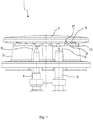
- the Fig. 1 shows a schematic side view of an embodiment of a gas burner 1 for a Marshsgar réelle.
- the Swsgar réelle can, for example, a Gas stove or a gas hob.
- the gas burner 1 comprises a burner lower part 2, which may be attached to a hob plate of the Swsgar réelles.
- the burner base 2 is made for example of an aluminum or magnesium material.
- the burner lower part 2 may be an aluminum die-cast component.
- the gas burner 1 further comprises an ignition element 3 for igniting a fuel gas / air mixture and a thermocouple 4 for flame monitoring.
- thermocouple 4 is connected to a gas shut-off valve of the gas burner 1, that when extinguishing a burner flame of the gas burner 1, the gas shut-off valve interrupts the gas flow to the gas burner 1.
- the ignition element 3 and the thermocouple 4 can be accommodated in receiving sections 5, 6 of the burner base 2.
- the gas burner 1 further comprises a burner cap 7, which is placed on the burner base 2.
- the burner cover 7 can be lifted off the burner lower part 2.
- the burner cover 7 has first gas distribution channels 8, which are provided in a gas distributor section 9 of the burner cover 7.
- the burner cover 7 may be made of an aluminum or ferrous material.
- the gas distributor section 9 rests on an upper edge 10 of the burner lower part 2. Gas outlet openings 11 of the gas burner 1 are defined by the first gas distribution channels 8 and the upper edge 10 of the burner base 2.
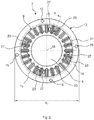
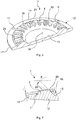
- the Fig. 2 shows an embodiment of a burner cap 7 in a plan view.
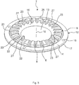
- the Fig. 3 shows the burner cap 7 according to the Fig. 2 in a perspective view.
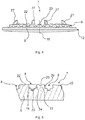
- the Fig. 4 shows the burner cap 7 according to the Fig. 2 in a side view.
- the Fig. 5 shows an enlarged sectional view of the burner cap 7 according to the Fig. 4
- the Fig. 6 shows a schematic sectional view of the burner cap 7 according to the Fig. 2 and the Fig. 7 shows an enlarged sectional view of the burner cap 7 according to the Fig. 6 ,
- the following is on the Fig. 2 to 7 simultaneously referred to.
- the burner cover 7 has a disk-shaped base portion 12.
- the disc-shaped base portion 12 preferably has a circular geometry.
- Connected to the base section 12 is the annular gas distributor section 9.
- the annular gas distributor section 9 runs around a disk-shaped central section 13 of the base section 12.
- the outer circumference is a annular outer portion 14 of the base portion 12 is provided.
- Blind holes 15 may be provided on the outer section 14. As the Fig. 2 shows four blind holes 15 may be provided, which are arranged in pairs opposite one another.
- the outer portion 14 and the gas distributor portion 9 are arranged concentrically with each other.
- the gas distributor section 9 comprises the first gas distribution channels 8.
- the number of the first gas distribution channels 8 is arbitrary. As the Fig. 2 and 3 For example, twenty-four first gas distribution channels 8 may be provided.
- the first gas distribution channels 8 extend radially from an inner surface 16 (FIG. Fig. 3 In particular, the first gas distribution channels 8 extend in the direction of the outer section 14 of the base section 12.
- the burner cover 7 has a central or symmetrical axis 18. Each first gas distribution channel 8 extends completely through the gas distributor section 9.
- each first gas distribution channel 8 has a T-shaped cross-sectional geometry which is open in the direction away from the base section 12.
- the first gas distribution channel 8 is open in the direction of the upper edge 10 of the burner base 2. That is, the first gas distribution channel 8 is in the transferred sense by the upper edge 10 of the burner base 2 to a T-shaped gas outlet opening 11 (FIG. Fig. 1 ) completed.
- the T-shaped cross-sectional geometry of each first gas distribution channel 8 has a horizontal portion 19 and a vertical portion 20. The horizontal portion 19 is open directionally away from the base portion 12.
- the horizontal portion 19 is 1.5 times to 6 times, preferably 2 times to 5 times, more preferably 2.5 times to 4 times as wide as the vertical portion 20.
- the vertical portion 20 extends preferably 1.5 times to 6 times, more preferably 2 times to 5 times, more preferably 2.5 times to 4 times as deep into the gas distributor section 9 as the horizontal section 19.
- the first gas distribution channels 8 are uniform over a circumference u 9 ( Fig. 2 ) of the gas distributor section 9 distributed.
- the inner surface 16 of the gas distribution section 9 is like the Fig. 7 shows, inclined to the base portion 12 and in particular obliquely inclined to the central portion 13 of the base portion 12.
- the first gas distribution channels 8 are inclined in the direction of the outer edge 17 of the base portion 12.
- the burner cap 7 also has an annular groove on 21 ( Fig. 6, 7 ), which completely orbits around the gas distributor section 9.
- the annular groove 21 is preferably formed in a quarter-circle.
- As the Fig. 6 shows the vertical portions 20 of the first gas distribution channels 8 in the annular groove 21.
- the horizontal portions 19 of the first gas distribution channels 8 are positioned so that they are arranged above the annular groove 21.
- the first gas distribution channels 8 are formed by webs 22 (FIG. Fig. 5 ) separated from each other.
- the burner cover 7 further comprises second gas distribution channels 23 which extend radially from the inner surface 16 of the gas distributor section 9 in the direction of the outer edge 17 of the base portion 12.
- Each second gas distribution channel 23 extends completely through the gas distributor section 9 and has a semicircular cross-sectional geometry open in the direction away from the base section 12.
- a gas outlet opening of the second gas distribution channels 23 is defined by the open semicircular geometry of the second gas distribution channels 23 and the upper edge 10 of the burner base 2.
- Each second gas distribution channel 23 extends through a web 22 of the gas distributor section 9 provided between two first gas distribution channels 8.
- the number of second gas distribution channels 23 is preferably less than the number of first gas distribution channels 8.
- four second gas distribution channels 23 are provided.
- the second gas distribution channels 23 are preferably distributed uniformly over the circumference u 9 of the gas distributor section 9. In particular, two second gas distribution channels 23 are positioned opposite each other.
- a second gas distribution channel 23 with respect to a horizontally disposed first gas distribution channel 8 may be arranged rotated by an angle ⁇ .
- the angle ⁇ can be 22.5 °, for example.
- every second gas distribution channel 23 between two first gas distribution channels 8 is arranged.
- the second gas distribution channel 23 facing side walls 24, 25 of two first gas distribution channel 8 formed rounded.
- each second gas distribution channel 23 is inclined by an angle ⁇ relative to the inner surface 16 of the gas distributor section 9.
- the angle ⁇ can be for example 20 °.
- a depth t of the second gas distribution channel 23 is 0.5 mm, for example.
- the burner cap 7 has, such as the Fig. 6 shows, further positioning elements 27 for positioning the burner cover 7 on the burner lower part 2 of the gas burner 1.
- the positioning elements 27 extend out of the gas distributor section 9 in the direction away from the base section 12.
- An upper side 28 of the gas distributor section 9 is inclined in the direction of the outer edge 17 of the base section 12.
- the gas distribution channels 8, 23 are positioned parallel to the upper side 28 and also extend obliquely from the middle section 13 in the direction of the outer section 14 to the outer section 14.
- the positioning elements 27 are arranged on the inclined top 28, the positioning elements 27 are arranged.
- the positioning elements 27 are in particular wedge-shaped and inclined in the direction of the outer edge 17 of the base portion 12. Due to the wedge-shaped geometry of the positioning elements 27, centering of the burner cover 7 on the burner base 2 can be achieved.
- receiving portions for receiving the positioning elements 27 are provided in the burner lower part 2 .
- the positioning elements 27 are distributed uniformly over the circumference u 9 of the gas distributor section 9 and positioned in pairs opposite one another. As the Fig. 2 and 3 show, the positioning elements 27 are preferably arranged on webs 22 of the gas distributor section 9, which are arranged adjacent to a web 22 with a second gas distribution channel 23.
- the burner cover 7 or the burner base section 12 has an outer diameter d 7 (FIG. Fig. 2 ) on.
- d 7 FIG. Fig. 2
- the first gas distribution channels 8 define the gas volume flow for the normal use of the gas burner 1.
- a particularly stable burner flame is achieved by the T-shaped cross-sectional geometry of the first gas distribution channels 8.
- the T-shaped Geometry of the first gas distribution channels 8 allows a particularly uniform outflow of the air / fuel gas mixture.
- the burner cap 7 can be positioned in a correct position relative to the burner lower part 2.
- a second gas distribution channel 23 can be positioned on an ignition element 3.
- the height of the burner cover 7 and thus the height of the gas burner 1 can be reduced.
- the efficiency of the gas burner 1 is increased.
- the height of the vessel carrier can be reduced, wherein the gas hob can be made with a lower height. Because the gas distribution channels 8, 23 extend obliquely in the direction of the outer edge 17 of the base section 12 starting from the inner surface 16 of the gas distributor section 9, an optimized burner flame angle can be achieved. The partial extinction of the burner flame is prevented to keep carbon monoxide emissions low.
- the Fig. 8 shows a schematic side view of another embodiment of a gas burner 1.
- the Fig. 9 shows a schematic plan view of an embodiment of a burner cap 7 for the gas burner 1 according to the Fig. 8
- the Fig. 10 shows the burner cap 7 in a perspective view.
- the Fig. 11 shows the burner cap 7 in a schematic sectional view. The following is on the 8 to 11 simultaneously referred to.
- the gas burner 1 has a burner lower part 2 and a burner cover 7.
- the gas burner 1 according to the Fig. 8 differs from the gas burner 1 according to the Fig. 1 , in that it has a higher rated power.
- the burner cap 7 has a larger diameter d 7 than the burner cap 7 according to the Fig. 2 .
- the number of first gas distribution channels 8 can be the number of the first Gas distribution channels 8 of the burner cap 7 according to the Fig. 2 correspond.
- Second gas distribution channels 23 are in the Fig. 9 to 11 not shown.
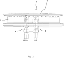
- the Fig. 12 shows a schematic side view of another embodiment of a gas burner 1.
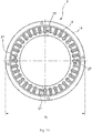
- the Fig. 13 shows a schematic plan view of an embodiment of a burner cap 7 for the gas burner 1 according to the Fig. 12
- the Fig. 14 shows the burner cap 7 in a perspective view.
- the Fig. 15 shows the burner cap 7 in a schematic sectional view. The following is on the Fig. 12 to 15 simultaneously referred to.
- the gas burner 1 according to the Fig. 12 differs from the gas burner 1 according to the Fig. 8 in that it has a higher rated power.
- the gas burner 1 has a burner lower part 2 and a burner cover 7.
- the diameter d 7 of the burner cap 7 according to the Fig. 13 is greater than the diameter d 7 of the burner cap 7 according to the Fig. 9 ,
- the burner cap 7 according to the Fig. 13 has a higher number of first gas distribution channels 8.
- the burner cover 7 differs from the burner cover 7 according to the Fig. 2 in that the positioning elements 27 are not wedge-shaped but frustoconical in shape.
- the relative position of the ignition element 3 relative to a second gas distribution channel 23 is exactly defined.
- the ignition is thereby improved.
- the gas burner 1 can be dimensioned flatter with the same or better efficiency.
- the gas burner 1 can be easily covered with a vessel carrier or Garrost.
- the geometry of the gas distribution channels 8, 23 thus makes it possible to reduce the height of the gas burner 1 with improved efficiency. Characterized in that the gas distribution channels 8, 23 extend obliquely upward in the direction of the outer portion 14 of the base portion 12, an improved burner flame angle can be achieved. This also improves the efficiency of the gas burner 1.
- the diameter d 7 of the burner cap 7 can be increased. The increased diameter d7 improves the flame distribution and the flame stability.
Landscapes
- Engineering & Computer Science (AREA)
- Chemical & Material Sciences (AREA)
- Combustion & Propulsion (AREA)
- Mechanical Engineering (AREA)
- General Engineering & Computer Science (AREA)
- Gas Burners (AREA)
- Baking, Grill, Roasting (AREA)
Claims (13)
- Brûleur à gaz (1) destiné à un appareil ménager de cuisson, muni d'une partie inférieure de brûleur (2) et d'un chapeau de brûleur (7) déposé sur la partie inférieure de brûleur (2) et présentant une section base discoïde (12) et une section répartiteur de gaz annulaire (9) reliée à la section base (12), dans lequel la section répartiteur de gaz (9) comporte des premiers canaux de répartiteur de gaz (8) qui s'étendent de manière radiale à partir d'une surface intérieure (16) de la section répartiteur de gaz (9) en direction d'un bord extérieur (17) de la section base (12), dans lequel chaque premier canal de répartiteur de gaz (8) s'étend à travers la section répartiteur de gaz (9) et présente une géométrie transversale en forme de T qui est ouverte en direction de la section base (12),
dans lequel la section répartiteur de gaz (9) comprend deux canaux de répartiteur de gaz (23) qui s'étendent de manière radiale à partir de la surface intérieure (16) de la section répartiteur de gaz (9) en direction du bord extérieur (17) de la section base (12), dans lequel chaque deuxième canal de répartiteur de gaz (23) s'étend à travers la section répartiteur de gaz (9) et présente une géométrie transversale de forme semi-circulaire qui est ouverte en direction de la section base (12), dans lequel une ouverture de sortie de gaz est définie à travers chaque deuxième canal de répartiteur de gaz (23) et le bord supérieur (10) de la partie inférieure de brûleur (2),
caractérisé en ce qu'une ouverture de sortie de gaz (11) en forme de T est définie à travers chaque premier canal de répartiteur de gaz (8) et un bord supérieur (10) de la partie inférieure de brûleur (2), et
une section transversale d'écoulement des deuxièmes canaux de répartiteur de gaz (23) est inférieure à une section transversale d'écoulement des premiers canaux de répartiteur de gaz (8). - Brûleur à gaz selon la revendication 1, caractérisé en ce que la géométrie transversale en forme de T présente une section horizontale (19) et une section verticale (20) et la section horizontale (19) est ouverte en direction de la section base (12).
- Brûleur à gaz selon la revendication 2, caractérisé en ce que la section horizontale (19) est 1,5 fois à 6 fois, de manière préférée 2 fois à 5 fois, de manière particulièrement préférée 2,5 fois à 4 fois plus large que la section verticale (20).
- Brûleur à gaz selon la revendication 2 ou 3, caractérisé en ce que la section verticale (20) s'étend 1,5 fois à 6 fois, de manière préférée 2 fois à 5 fois, de manière particulièrement préférée 2,5 fois à 4 fois plus profondément dans la section répartiteur de gaz (9) que la section horizontale (19).
- Brûleur à gaz selon l'une quelconque des revendications 1 à 4, caractérisé en ce que les premiers canaux de répartiteur de gaz (8) sont agencés répartis de manière régulière sur un pourtour (Ug) de la section répartiteur de gaz (9).
- Brûleur à gaz selon l'une quelconque des revendications 1 à 5, caractérisé en ce que la surface intérieure (16) de la section répartiteur de gaz (9) est inclinée en diagonale par rapport à la section base(12).
- Brûleur à gaz selon l'une quelconque des revendications 1 à 6, caractérisé par une rainure annulaire (21) qui fait le tour de la section répartiteur de gaz (9).
- Brûleur à gaz selon l'une quelconque des revendications 1 à 7, caractérisé par des éléments de positionnement (27) destinés au positionnement du chapeau de brûleur (7) sur une partie inférieure (2) du brûleur à gaz (1) et en ce que les éléments de positionnement (27) s'étendent à partir de la section répartiteur de gaz (9) en direction de la section base (12).
- Brûleur à gaz selon la revendication 8, caractérisé en ce que les éléments de positionnement (27) sont agencés répartis de manière régulière sur un pourtour (U9) de la section répartiteur de gaz (9) et sont positionnés les uns en face des autres par paire.
- Brûleur à gaz selon la revendication 8 ou 9, caractérisé en ce que les éléments de positionnement (27) sont en forme de coin.
- Brûleur à gaz selon l'une quelconque des revendications 1 à 10, caractérisé en ce qu'une face supérieure (28) de la section répartiteur de gaz (9) est inclinée en direction du bord extérieur (17) de la section base (12).
- Brûleur à gaz selon l'une quelconque des revendications 1 à 11, caractérisé en ce que chaque deuxième canal de répartiteur de gaz (23) s'étend à travers une garniture (22), prévue entre deux premiers canaux de répartiteur de gaz (8) de la section répartiteur de gaz (9).
- Brûleur à gaz selon l'une quelconque des revendications 1 à 12, caractérisé en ce que les deuxièmes canaux de répartiteur de gaz (23) sont agencés répartis de manière régulière sur un pourtour (U9) de la section répartiteur de gaz (9) et sont positionnés les uns en face des autres par paire.
Applications Claiming Priority (2)
| Application Number | Priority Date | Filing Date | Title |
|---|---|---|---|
| ES201530437A ES2584921B1 (es) | 2015-03-31 | 2015-03-31 | Tapa de quemador y quemador de gas |
| PCT/IB2016/051161 WO2016157003A1 (fr) | 2015-03-31 | 2016-03-02 | Couvercle de brûleur et brûleur à gaz |
Publications (2)
| Publication Number | Publication Date |
|---|---|
| EP3278024A1 EP3278024A1 (fr) | 2018-02-07 |
| EP3278024B1 true EP3278024B1 (fr) | 2019-05-08 |
Family
ID=55485027
Family Applications (1)
| Application Number | Title | Priority Date | Filing Date |
|---|---|---|---|
| EP16708456.5A Active EP3278024B1 (fr) | 2015-03-31 | 2016-03-02 | Brûleur à gaz avec couvercle de brûleur |
Country Status (6)
| Country | Link |
|---|---|
| US (1) | US10415823B2 (fr) |
| EP (1) | EP3278024B1 (fr) |
| CN (1) | CN107438741B (fr) |
| ES (1) | ES2584921B1 (fr) |
| TR (1) | TR201907520T4 (fr) |
| WO (1) | WO2016157003A1 (fr) |
Families Citing this family (7)
| Publication number | Priority date | Publication date | Assignee | Title |
|---|---|---|---|---|
| JP6671233B2 (ja) * | 2016-04-28 | 2020-03-25 | リンナイ株式会社 | コンロバーナー |
| US10551056B2 (en) * | 2017-02-23 | 2020-02-04 | Whirlpool Corporation | Burner base |
| CN108332238B (zh) * | 2018-02-08 | 2020-09-08 | 吴联凯 | 一种中餐式燃气灶 |
| CN108317544B (zh) * | 2018-02-08 | 2019-12-31 | 佛山市顺德区吉孚电器有限公司 | 一种中餐式燃气炒菜灶 |
| US11460190B2 (en) * | 2019-07-29 | 2022-10-04 | Haier Us Appliance Solutions, Inc. | Gas burner assembly for a cooktop appliance |
| JP7252619B2 (ja) * | 2019-08-27 | 2023-04-05 | 株式会社パロマ | コンロバーナ |
| DE202024102798U1 (de) | 2024-05-29 | 2024-07-18 | AVB UG (haftungsbeschränkt) | Wärmeverteilerplatte für einen Backofen mit externer Wärmezufuhr |
Family Cites Families (12)
| Publication number | Priority date | Publication date | Assignee | Title |
|---|---|---|---|---|
| FR461634A (fr) * | 1913-08-09 | 1914-01-07 | Francois Eugene Nicora | Bruleur à gaz à double couronne |
| DE1950506C3 (de) * | 1969-10-07 | 1981-03-12 | Metallwerke Gebr. Seppelfricke Gmbh & Co, 4650 Gelsenkirchen | Gasbrenner für Gasherde |
| US6095802A (en) * | 1995-08-31 | 2000-08-01 | Eaton Corporation | Gaseous fuel burner and method of making same |
| US5690483A (en) | 1996-07-17 | 1997-11-25 | Eaton Coporation | Gaseous fuel burner |
| US6371754B1 (en) * | 2000-01-04 | 2002-04-16 | General Electric Company | Flame stabilizing channel for increased turn down of gas burners |
| EP1512908A1 (fr) * | 2003-09-05 | 2005-03-09 | Electrolux Home Products Corporation N.V. | Brûleur à gaz |
| EP2258982B1 (fr) * | 2007-10-23 | 2019-01-16 | Electrolux Home Products Corporation N.V. | Brûleur à gaz amélioré |
| MX345335B (es) * | 2009-12-18 | 2017-01-25 | Mabe S A De C V * | Quemador de tres sectores de flama. |
| ITAN20120036A1 (it) | 2011-04-19 | 2012-10-20 | Somipress Societa Metalli Iniett Ati S P A | Fornello a gas con fiamma rivolta verso l'interno. |
| CN104713087B (zh) * | 2015-03-12 | 2017-10-27 | 广东美的厨房电器制造有限公司 | 底杯盖及燃烧器及燃气用具 |
| EP3270056A4 (fr) * | 2015-03-13 | 2018-10-17 | Guangdong Midea Kitchen Appliances | Brûleur |
| ITUB20153850A1 (it) * | 2015-04-24 | 2017-03-24 | Defendi Italy Srl | Bruciatore a gas con piu corone di fiamme per piani di cottura. |
-
2015
- 2015-03-31 ES ES201530437A patent/ES2584921B1/es not_active Expired - Fee Related
-
2016
- 2016-03-02 TR TR2019/07520T patent/TR201907520T4/tr unknown
- 2016-03-02 WO PCT/IB2016/051161 patent/WO2016157003A1/fr not_active Ceased
- 2016-03-02 US US15/559,085 patent/US10415823B2/en not_active Expired - Fee Related
- 2016-03-02 EP EP16708456.5A patent/EP3278024B1/fr active Active
- 2016-03-02 CN CN201680019858.XA patent/CN107438741B/zh active Active
Non-Patent Citations (1)
| Title |
|---|
| None * |
Also Published As
| Publication number | Publication date |
|---|---|
| WO2016157003A1 (fr) | 2016-10-06 |
| ES2584921A1 (es) | 2016-09-30 |
| CN107438741B (zh) | 2020-07-07 |
| ES2584921B1 (es) | 2017-07-11 |
| CN107438741A (zh) | 2017-12-05 |
| EP3278024A1 (fr) | 2018-02-07 |
| US10415823B2 (en) | 2019-09-17 |
| TR201907520T4 (tr) | 2019-06-21 |
| US20180073731A1 (en) | 2018-03-15 |
Similar Documents
| Publication | Publication Date | Title |
|---|---|---|
| EP3278024B1 (fr) | Brûleur à gaz avec couvercle de brûleur | |
| EP2211095B1 (fr) | Brûleur à gaz | |
| EP1028286B1 (fr) | Plaque de cuisson pour cuisinières à gaz | |
| EP2290287B1 (fr) | Chapeau de brûleur pour cuisinière à gaz et brûleur doté d'un tel chapeau | |
| DE69315233T2 (de) | Gaskochherdbrenner mit drei konzentrischen Flammen | |
| EP1134499B1 (fr) | Réchaud | |
| EP2397757B1 (fr) | Chapeau de brûleur pour cuisinière à gaz et brûleur doté d'un tel chapeau | |
| EP2090826A1 (fr) | Brûleur à gaz | |
| DE10315343A1 (de) | Gasbrenner mit Abdeckung | |
| EP3679301B1 (fr) | Grille, table de cuisson à gaz et procédé de fabrication d'une grille | |
| EP2618054A2 (fr) | Brûleur à gaz avec au moins trois cercles de flammes | |
| DE19931686A1 (de) | Gasbrenner | |
| EP3255341B1 (fr) | Brûleur à gaz et appareil de cuisson ménager | |
| EP3479022B1 (fr) | Brûleur à gaz et appareil ménager de cuisson | |
| EP2439449B1 (fr) | Brûleur à gaz pour un réchaud | |
| WO2019053542A1 (fr) | Brûleur à gaz, dispositif de brûleur à gaz et appareil ménager de cuisson | |
| EP3990832A1 (fr) | Support de casserole, plaque de cuisson à gaz et procédé pour la fabrication d'un support de casserole | |
| EP3198194B1 (fr) | Brûleur à gaz, plaque de cuisson au gaz, gazinière et procédé permettant de changer le gaz de combustion d'un brûleur à gaz | |
| DE102008019572B4 (de) | Brennerkrone mit Ausgabelöchern auf verschiedenen Ebenen und abwechselnd, einstückig, mit hoher Leistung für Brenner von Großküchen zum Kochen von Lebensmitteln | |
| EP2473784B1 (fr) | Dispositif brûleur à gaz et foyer de cuisson à gaz | |
| DE10041472C1 (de) | Gasstrahlungsbrenner | |
| DE3415946C2 (fr) | ||
| EP1067334A1 (fr) | Brûleur à gaz d'appareils de cuisson pour produits alimentaires | |
| DE708130C (de) | Drosseleinrichtung fuer den Rauchgaskanal von Kuechenherden | |
| DE19820445A1 (de) | Gasbrenner-Unterteil für Kochstellen |
Legal Events
| Date | Code | Title | Description |
|---|---|---|---|
| STAA | Information on the status of an ep patent application or granted ep patent |
Free format text: STATUS: THE INTERNATIONAL PUBLICATION HAS BEEN MADE |
|
| PUAI | Public reference made under article 153(3) epc to a published international application that has entered the european phase |
Free format text: ORIGINAL CODE: 0009012 |
|
| STAA | Information on the status of an ep patent application or granted ep patent |
Free format text: STATUS: REQUEST FOR EXAMINATION WAS MADE |
|
| 17P | Request for examination filed |
Effective date: 20171102 |
|
| AK | Designated contracting states |
Kind code of ref document: A1 Designated state(s): AL AT BE BG CH CY CZ DE DK EE ES FI FR GB GR HR HU IE IS IT LI LT LU LV MC MK MT NL NO PL PT RO RS SE SI SK SM TR |
|
| AX | Request for extension of the european patent |
Extension state: BA ME |
|
| DAV | Request for validation of the european patent (deleted) | ||
| DAX | Request for extension of the european patent (deleted) | ||
| GRAP | Despatch of communication of intention to grant a patent |
Free format text: ORIGINAL CODE: EPIDOSNIGR1 |
|
| STAA | Information on the status of an ep patent application or granted ep patent |
Free format text: STATUS: GRANT OF PATENT IS INTENDED |
|
| INTG | Intention to grant announced |
Effective date: 20181109 |
|
| GRAS | Grant fee paid |
Free format text: ORIGINAL CODE: EPIDOSNIGR3 |
|
| GRAA | (expected) grant |
Free format text: ORIGINAL CODE: 0009210 |
|
| STAA | Information on the status of an ep patent application or granted ep patent |
Free format text: STATUS: THE PATENT HAS BEEN GRANTED |
|
| AK | Designated contracting states |
Kind code of ref document: B1 Designated state(s): AL AT BE BG CH CY CZ DE DK EE ES FI FR GB GR HR HU IE IS IT LI LT LU LV MC MK MT NL NO PL PT RO RS SE SI SK SM TR |
|
| REG | Reference to a national code |
Ref country code: GB Ref legal event code: FG4D Free format text: NOT ENGLISH |
|
| REG | Reference to a national code |
Ref country code: CH Ref legal event code: EP Ref country code: AT Ref legal event code: REF Ref document number: 1130724 Country of ref document: AT Kind code of ref document: T Effective date: 20190515 |
|
| REG | Reference to a national code |
Ref country code: DE Ref legal event code: R096 Ref document number: 502016004562 Country of ref document: DE |
|
| REG | Reference to a national code |
Ref country code: IE Ref legal event code: FG4D Free format text: LANGUAGE OF EP DOCUMENT: GERMAN |
|
| REG | Reference to a national code |
Ref country code: NL Ref legal event code: MP Effective date: 20190508 |
|
| REG | Reference to a national code |
Ref country code: LT Ref legal event code: MG4D |
|
| PG25 | Lapsed in a contracting state [announced via postgrant information from national office to epo] |
Ref country code: HR Free format text: LAPSE BECAUSE OF FAILURE TO SUBMIT A TRANSLATION OF THE DESCRIPTION OR TO PAY THE FEE WITHIN THE PRESCRIBED TIME-LIMIT Effective date: 20190508 Ref country code: LT Free format text: LAPSE BECAUSE OF FAILURE TO SUBMIT A TRANSLATION OF THE DESCRIPTION OR TO PAY THE FEE WITHIN THE PRESCRIBED TIME-LIMIT Effective date: 20190508 Ref country code: NO Free format text: LAPSE BECAUSE OF FAILURE TO SUBMIT A TRANSLATION OF THE DESCRIPTION OR TO PAY THE FEE WITHIN THE PRESCRIBED TIME-LIMIT Effective date: 20190808 Ref country code: NL Free format text: LAPSE BECAUSE OF FAILURE TO SUBMIT A TRANSLATION OF THE DESCRIPTION OR TO PAY THE FEE WITHIN THE PRESCRIBED TIME-LIMIT Effective date: 20190508 Ref country code: SE Free format text: LAPSE BECAUSE OF FAILURE TO SUBMIT A TRANSLATION OF THE DESCRIPTION OR TO PAY THE FEE WITHIN THE PRESCRIBED TIME-LIMIT Effective date: 20190508 Ref country code: FI Free format text: LAPSE BECAUSE OF FAILURE TO SUBMIT A TRANSLATION OF THE DESCRIPTION OR TO PAY THE FEE WITHIN THE PRESCRIBED TIME-LIMIT Effective date: 20190508 Ref country code: PT Free format text: LAPSE BECAUSE OF FAILURE TO SUBMIT A TRANSLATION OF THE DESCRIPTION OR TO PAY THE FEE WITHIN THE PRESCRIBED TIME-LIMIT Effective date: 20190908 Ref country code: AL Free format text: LAPSE BECAUSE OF FAILURE TO SUBMIT A TRANSLATION OF THE DESCRIPTION OR TO PAY THE FEE WITHIN THE PRESCRIBED TIME-LIMIT Effective date: 20190508 Ref country code: ES Free format text: LAPSE BECAUSE OF FAILURE TO SUBMIT A TRANSLATION OF THE DESCRIPTION OR TO PAY THE FEE WITHIN THE PRESCRIBED TIME-LIMIT Effective date: 20190508 |
|
| PG25 | Lapsed in a contracting state [announced via postgrant information from national office to epo] |
Ref country code: GR Free format text: LAPSE BECAUSE OF FAILURE TO SUBMIT A TRANSLATION OF THE DESCRIPTION OR TO PAY THE FEE WITHIN THE PRESCRIBED TIME-LIMIT Effective date: 20190809 Ref country code: BG Free format text: LAPSE BECAUSE OF FAILURE TO SUBMIT A TRANSLATION OF THE DESCRIPTION OR TO PAY THE FEE WITHIN THE PRESCRIBED TIME-LIMIT Effective date: 20190808 Ref country code: LV Free format text: LAPSE BECAUSE OF FAILURE TO SUBMIT A TRANSLATION OF THE DESCRIPTION OR TO PAY THE FEE WITHIN THE PRESCRIBED TIME-LIMIT Effective date: 20190508 Ref country code: RS Free format text: LAPSE BECAUSE OF FAILURE TO SUBMIT A TRANSLATION OF THE DESCRIPTION OR TO PAY THE FEE WITHIN THE PRESCRIBED TIME-LIMIT Effective date: 20190508 |
|
| PG25 | Lapsed in a contracting state [announced via postgrant information from national office to epo] |
Ref country code: EE Free format text: LAPSE BECAUSE OF FAILURE TO SUBMIT A TRANSLATION OF THE DESCRIPTION OR TO PAY THE FEE WITHIN THE PRESCRIBED TIME-LIMIT Effective date: 20190508 Ref country code: DK Free format text: LAPSE BECAUSE OF FAILURE TO SUBMIT A TRANSLATION OF THE DESCRIPTION OR TO PAY THE FEE WITHIN THE PRESCRIBED TIME-LIMIT Effective date: 20190508 Ref country code: RO Free format text: LAPSE BECAUSE OF FAILURE TO SUBMIT A TRANSLATION OF THE DESCRIPTION OR TO PAY THE FEE WITHIN THE PRESCRIBED TIME-LIMIT Effective date: 20190508 Ref country code: CZ Free format text: LAPSE BECAUSE OF FAILURE TO SUBMIT A TRANSLATION OF THE DESCRIPTION OR TO PAY THE FEE WITHIN THE PRESCRIBED TIME-LIMIT Effective date: 20190508 Ref country code: SK Free format text: LAPSE BECAUSE OF FAILURE TO SUBMIT A TRANSLATION OF THE DESCRIPTION OR TO PAY THE FEE WITHIN THE PRESCRIBED TIME-LIMIT Effective date: 20190508 |
|
| REG | Reference to a national code |
Ref country code: DE Ref legal event code: R097 Ref document number: 502016004562 Country of ref document: DE |
|
| PG25 | Lapsed in a contracting state [announced via postgrant information from national office to epo] |
Ref country code: SM Free format text: LAPSE BECAUSE OF FAILURE TO SUBMIT A TRANSLATION OF THE DESCRIPTION OR TO PAY THE FEE WITHIN THE PRESCRIBED TIME-LIMIT Effective date: 20190508 |
|
| PLBE | No opposition filed within time limit |
Free format text: ORIGINAL CODE: 0009261 |
|
| STAA | Information on the status of an ep patent application or granted ep patent |
Free format text: STATUS: NO OPPOSITION FILED WITHIN TIME LIMIT |
|
| 26N | No opposition filed |
Effective date: 20200211 |
|
| PG25 | Lapsed in a contracting state [announced via postgrant information from national office to epo] |
Ref country code: PL Free format text: LAPSE BECAUSE OF FAILURE TO SUBMIT A TRANSLATION OF THE DESCRIPTION OR TO PAY THE FEE WITHIN THE PRESCRIBED TIME-LIMIT Effective date: 20190508 |
|
| PG25 | Lapsed in a contracting state [announced via postgrant information from national office to epo] |
Ref country code: SI Free format text: LAPSE BECAUSE OF FAILURE TO SUBMIT A TRANSLATION OF THE DESCRIPTION OR TO PAY THE FEE WITHIN THE PRESCRIBED TIME-LIMIT Effective date: 20190508 |
|
| PG25 | Lapsed in a contracting state [announced via postgrant information from national office to epo] |
Ref country code: MC Free format text: LAPSE BECAUSE OF FAILURE TO SUBMIT A TRANSLATION OF THE DESCRIPTION OR TO PAY THE FEE WITHIN THE PRESCRIBED TIME-LIMIT Effective date: 20190508 |
|
| REG | Reference to a national code |
Ref country code: CH Ref legal event code: PL |
|
| REG | Reference to a national code |
Ref country code: BE Ref legal event code: MM Effective date: 20200331 |
|
| PG25 | Lapsed in a contracting state [announced via postgrant information from national office to epo] |
Ref country code: LU Free format text: LAPSE BECAUSE OF NON-PAYMENT OF DUE FEES Effective date: 20200302 |
|
| PG25 | Lapsed in a contracting state [announced via postgrant information from national office to epo] |
Ref country code: FR Free format text: LAPSE BECAUSE OF NON-PAYMENT OF DUE FEES Effective date: 20200331 Ref country code: IE Free format text: LAPSE BECAUSE OF NON-PAYMENT OF DUE FEES Effective date: 20200302 Ref country code: CH Free format text: LAPSE BECAUSE OF NON-PAYMENT OF DUE FEES Effective date: 20200331 Ref country code: LI Free format text: LAPSE BECAUSE OF NON-PAYMENT OF DUE FEES Effective date: 20200331 |
|
| PG25 | Lapsed in a contracting state [announced via postgrant information from national office to epo] |
Ref country code: BE Free format text: LAPSE BECAUSE OF NON-PAYMENT OF DUE FEES Effective date: 20200331 |
|
| REG | Reference to a national code |
Ref country code: AT Ref legal event code: MM01 Ref document number: 1130724 Country of ref document: AT Kind code of ref document: T Effective date: 20210302 |
|
| PG25 | Lapsed in a contracting state [announced via postgrant information from national office to epo] |
Ref country code: MT Free format text: LAPSE BECAUSE OF FAILURE TO SUBMIT A TRANSLATION OF THE DESCRIPTION OR TO PAY THE FEE WITHIN THE PRESCRIBED TIME-LIMIT Effective date: 20190508 Ref country code: CY Free format text: LAPSE BECAUSE OF FAILURE TO SUBMIT A TRANSLATION OF THE DESCRIPTION OR TO PAY THE FEE WITHIN THE PRESCRIBED TIME-LIMIT Effective date: 20190508 |
|
| PG25 | Lapsed in a contracting state [announced via postgrant information from national office to epo] |
Ref country code: MK Free format text: LAPSE BECAUSE OF FAILURE TO SUBMIT A TRANSLATION OF THE DESCRIPTION OR TO PAY THE FEE WITHIN THE PRESCRIBED TIME-LIMIT Effective date: 20190508 Ref country code: IS Free format text: LAPSE BECAUSE OF FAILURE TO SUBMIT A TRANSLATION OF THE DESCRIPTION OR TO PAY THE FEE WITHIN THE PRESCRIBED TIME-LIMIT Effective date: 20190908 |
|
| PG25 | Lapsed in a contracting state [announced via postgrant information from national office to epo] |
Ref country code: AT Free format text: LAPSE BECAUSE OF NON-PAYMENT OF DUE FEES Effective date: 20210302 |
|
| PGFP | Annual fee paid to national office [announced via postgrant information from national office to epo] |
Ref country code: DE Payment date: 20230331 Year of fee payment: 8 |
|
| P01 | Opt-out of the competence of the unified patent court (upc) registered |
Effective date: 20230504 |
|
| REG | Reference to a national code |
Ref country code: DE Ref legal event code: R119 Ref document number: 502016004562 Country of ref document: DE |
|
| PG25 | Lapsed in a contracting state [announced via postgrant information from national office to epo] |
Ref country code: DE Free format text: LAPSE BECAUSE OF NON-PAYMENT OF DUE FEES Effective date: 20241001 |
|
| PG25 | Lapsed in a contracting state [announced via postgrant information from national office to epo] |
Ref country code: DE Free format text: LAPSE BECAUSE OF NON-PAYMENT OF DUE FEES Effective date: 20241001 |
|
| PGFP | Annual fee paid to national office [announced via postgrant information from national office to epo] |
Ref country code: IT Payment date: 20250331 Year of fee payment: 10 |
|
| PGFP | Annual fee paid to national office [announced via postgrant information from national office to epo] |
Ref country code: GB Payment date: 20260324 Year of fee payment: 11 |
|
| PGFP | Annual fee paid to national office [announced via postgrant information from national office to epo] |
Ref country code: TR Payment date: 20260224 Year of fee payment: 11 |